Table of Contents
Advertisement
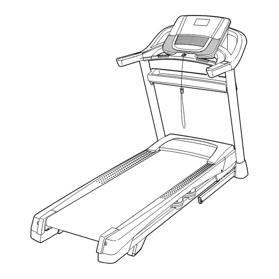
Model No. HETL14915.0
Serial No.
Write the serial number in the space
above for reference.
Serial Number
Decal
CUSTOMER SERVICE
UNITED KINGDOM
Call: 0330 123 1045
From Ireland: 053 92 36102
Website: www.iconsupport.eu
E-mail: csuk@iconeurope.com
Write:
ICON Health & Fitness, Ltd.
Unit 1D, The Gateway
Fryers Way, Silkwood Park
OSSETT
WF5 9TJ
UNITED KINGDOM
AUSTRALIA
Call: 1800 993 770
E-mail: australiacc@iconfitness.com
Write:
ICON Health & Fitness
PO Box 635
WINSTON HILLS NSW 2153
AUSTRALIA
CAUTION
Read all precautions and instruc-
tions in this manual before using
this equipment. Save this manual
for future reference.
USER'S MANUAL
www.iconeurope.com
Advertisement
Table of Contents

Related Manuals for HEALTH RIDER H200T HETL14915.0

Summary of Contents for HEALTH RIDER H200T HETL14915.0
- Page 1 Model No. HETL14915.0 Serial No. USER’S MANUAL Write the serial number in the space above for reference. Serial Number Decal CUSTOMER SERVICE UNITED KINGDOM Call: 0330 123 1045 From Ireland: 053 92 36102 Website: www.iconsupport.eu E-mail: csuk@iconeurope.com Write: ICON Health & Fitness, Ltd. Unit 1D, The Gateway Fryers Way, Silkwood Park OSSETT...
-
Page 2: Table Of Contents
TABLE OF CONTENTS WARNING DECAL PLACEMENT ............. . .2 IMPORTANT PRECAUTIONS . -
Page 3: Important Precautions
IMPORTANT PRECAUTIONS WARNING: To reduce the risk of burns, fire, electric shock, or injury to persons, read all important precautions and instructions in this manual and all warnings on your treadmill before using your treadmill. ICON assumes no responsibility for personal injury or property damage sus- tained by or through the use of this product. - Page 4 22. Never leave the treadmill unattended while 26. Inspect and properly tighten all parts of the it is running. Always remove the key, press treadmill regularly. the power switch into the off position (see DANGER: the drawing on page 5 for the location of the Always unplug the power power switch), and unplug the power cord cord immediately after use, before clean-...
-
Page 5: Before You Begin
BEFORE YOU BEGIN Thank you for selecting the revolutionary reading this manual, please see the front cover of this HEALTHRIDER H200T treadmill. The H200T treadmill manual. To help us assist you, please note the product ® offers an impressive selection of features designed model number and serial number before contacting us. -
Page 6: Part Identification Chart
PART IDENTIFICATION CHART Use the drawings below to identify small parts used for assembly. The number in parentheses below each draw- ing is the key number of the part, from the PART LIST near the end of this manual. The number following the key number is the quantity used for assembly. -
Page 7: Assembly
ASSEMBLY • Assembly requires two persons. • To identify small parts, see page 6. • Place all parts in a cleared area and remove the • Assembly requires the following tools: packing materials. Do not dispose of the packing the included hex key materials until you finish all assembly steps. - Page 8 2. Make sure that the power cord is unplugged. Wire Press a Base Cap (74) into each side of the Base (94). Next, remove the tie securing the Upright Wire (81) to the front of the Base (94). Identify the Right Upright (90). Have a second person hold the Right Upright near the Base (94).
- Page 9 4. Insert a Wheel Spacer (63) into a Front Wheel (62). Hold the Front Wheel inside the bottom of the Right Upright (90), and insert a 3/8" x 4" Screw (7) with a 3/8" Star Washer (13) into the Right Upright and the Front Wheel. Repeat this step on the left side of the tread- mill (not shown).
-
Page 10: 3/4" Screws (4
6. Remove and save the four indicated 5/16" x 3/4" Screws (4). Identify the Left and Right Base Covers (82, 83). Slide the Left Base Cover onto the Left Upright (89), and slide the Right Base Cover onto the Right Upright (90). Do not press the Base Covers into place yet. -
Page 11: 3/4" Screws (4
8. Insert the Upright Wire (81) into the bottom of the right handrail assembly (D) and out of the front as shown. Attach the right handrail assembly (D) to the Right Upright (90) with two 5/16" x 2 1/2" Screws (28) and two 5/16"... - Page 12 10. Identify the Right and Left Trays (27, 36). Attach the Trays (27, 36) to the Console Base (64) with eight #8 x 1/2" Screws (1); do not overtighten the Screws. Reattach the Console Frame (18) with the six #8 x 3/4"...
-
Page 13: 3/4" Screws (4
12. Hold the console assembly (G) near the Pulse Crossbar (93). Connect the ground wire from the console assembly to the Console Ground Wire (58) on the Pulse Crossbar. Next, set the console assembly (G) on the brack- ets on the Handrails (86); do not pinch any wires. - Page 14 15. Attach the Tray (88) to the Upright Crossbar (31) with four #8 x 3/4" Screws (2); start all four Screws, and then tighten them. 16. Insert the Upright Wire (81) and the handrail wire (F) through the two indicated looped ties on the console assembly (G).
- Page 15 17. Insert the handrail wire (F) on the left side through the two indicated looped ties on the console assembly (G) and make the connection to the wire from the console. Insert all excess wires into the console assembly (G). Then, pull the two ties tight against the wires and cut off the ends of the ties.
-
Page 16: 3/4" Screws (4
19. Note: If the treadmill is assembled on a smooth surface, it may roll forward during this step. Raise the Frame (56) to the upright position. Brackets Have a second person hold the Frame until step 21 is completed. Remove the two 5/16" x 3/4" Screws (4) from the Latch Crossbar (38). - Page 17 21. Remove the 5/16" Nut (12) and the 5/16" x 2 1/4" Bolt (3) from the bracket on the Latch Crossbar (38). Align the upper end of the Storage Latch (53) with the bracket on the Latch Crossbar (38), and insert the 5/16" x 2 1/4" Bolt (3) through the bracket and the Storage Latch.
-
Page 18: The Chest Heart Rate Monitor
THE CHEST HEART RATE MONITOR HOW TO PUT ON THE HEART RATE MONITOR • Store the heart rate monitor in a warm, dry place. Do not store the heart rate monitor in a plastic bag or If the heart rate monitor looks like the one shown other container that may trap moisture. -
Page 19: How To Use The Treadmill
HOW TO USE THE TREADMILL HOW TO PLUG IN THE POWER CORD Follow the steps below to plug in the power cord. This product must be earthed. If it should malfunc- 1. Plug the indicated end of the power cord into the tion or break down, earthing provides a path of least socket on the treadmill. - Page 20 CONSOLE DIAGRAM FEATURES OF THE CONSOLE You can even listen to your favorite workout music or audio books with the console’s sound system while you The treadmill console offers an impressive array of exercise. features designed to make your workouts more effec- To turn on the power, see page 21.
- Page 21 HOW TO TURN ON THE POWER HOW TO USE THE MANUAL MODE IMPORTANT: If the treadmill has been exposed to 1. Insert the key into the console. cold temperatures, allow it to warm to room tem- perature before you turn on the power. If you do See HOW TO TURN ON THE POWER at the left.
- Page 22 5. Follow your progress with the displays. As you exercise, the workout intensity level bar will indicate the approximate intensity level of your As you walk or run on the treadmill, the display can exercise. show the following workout information: •...
- Page 23 7. Turn on the fan if desired. 3. Start the workout. The fan features multiple speed settings and an Press the Start button or the Speed increase button auto mode. When the auto mode is selected, to start the workout. A moment after you press the the speed of the fan will automatically increase button, the treadmill will automatically adjust to the and decrease as the intensity of your exercise...
- Page 24 HOW TO USE A SET-A-GOAL WORKOUT If the speed or incline setting is too high or too low at any time during the workout, you can manu- ally override the setting by pressing the Speed or 1. Insert the key into the console. Incline buttons;...
- Page 25 6. Turn on the fan if desired. 3. Select a user. See step 7 on page 23. If more than one user is registered, you can switch users in the iFit main screen. Press the increase 7. When you are finished exercising, remove the and decrease buttons next to the Enter button to key from the console.
- Page 26 5. Start the workout. 8. Turn on the fan if desired. See step 3 on page 23. See step 7 on page 23. 9. When you are finished exercising, remove the During some workouts, an audio coach may guide you through your workout. You can select a setting key from the console.
- Page 27 THE SETTINGS MODE CONTRAST LVL—Press the Incline increase and decrease buttons to adjust the contrast level of the The console features a settings mode that keeps track display. of treadmill information and allows you to personalize If a module is connected, you may also select console settings.
-
Page 28: How To Fold And Move The Treadmill
HOW TO FOLD AND MOVE THE TREADMILL HOW TO FOLD THE TREADMILL HOW TO MOVE THE TREADMILL To avoid damaging the treadmill, adjust the incline Before moving the treadmill, fold it as described at the to zero before you fold the treadmill. Then, remove left. -
Page 29: Maintenance And Troubleshooting
MAINTENANCE AND TROUBLESHOOTING MAINTENANCE SYMPTOM: The power turns off during use Regularly clean the treadmill and keep the walking a. Check the power switch (see drawing c at the left). belt clean and dry. First, press the power switch into If the switch has tripped, wait for five minutes and the off position and unplug the power cord. - Page 30 SYMPTOM: The displays of the console do not SYMPTOM: The walking belt slows when walked on function properly a. If an extension cord is needed, use only a 3-con- a. Remove the key from the console and UNPLUG ductor, 14-gauge (1 mm ) cord that is no longer THE POWER CORD.
- Page 31 SYMPTOM: The walking belt is not centered SYMPTOM: The walking belt slips when walked on between the foot rails. IMPORTANT: If the walking belt rubs against the foot rails, the walking belt a. First, remove the key and UNPLUG THE POWER may become damaged.
-
Page 32: Exercise Guidelines
EXERCISE GUIDELINES Burning Fat—To burn fat effectively, you must exer- WARNING: cise at a low intensity level for a sustained period of Before beginning this time. During the first few minutes of exercise, your or any exercise program, consult your physi- body uses carbohydrate calories for energy. - Page 33 SUGGESTED STRETCHES The correct form for several basic stretches is shown at the right. Move slowly as you stretch —never bounce. 1. Toe Touch Stretch Stand with your knees bent slightly and slowly bend forward from your hips. Allow your back and shoulders to relax as you reach down toward your toes as far as possible.
-
Page 34: Part List
PART LIST Model No. HETL14915.0 R0315A Key No. Qty. Description Key No. Qty. Description #8 x 1/2" Screw Reed Switch Clip #8 x 3/4" Screw Reed Switch 5/16" x 2 1/4" Bolt Storage Latch 5/16" x 3/4" Screw Drive Motor #10 Star Washer Motor Belt 5/16"... - Page 35 Key No. Qty. Description Key No. Qty. Description #8 x 3/4" Washer Head Screw Electronics Bracket #8 x 3/4" Truss Head Screw Filter Left Rear Cap Motor Isolator Right Rear Cap Grounding Strap 1/4" Nut Receptacle Controller Clamp Base Pad #8 x 1 3/4"...
-
Page 36: Exploded Drawing
EXPLODED DRAWING A Model No. HETL14915.0 R0315A... - Page 37 EXPLODED DRAWING B Model No. HETL14915.0 R0315A...
- Page 38 EXPLODED DRAWING C Model No. HETL14915.0 R0315A...
- Page 39 EXPLODED DRAWING D Model No. HETL14915.0 R0315A...
-
Page 40: Ordering Replacement Parts
ORDERING REPLACEMENT PARTS To order replacement parts, please see the front cover of this manual. To help us assist you, be prepared to provide the following information when contacting us: • the model number and serial number of the product (see the front cover of this manual) •...