Table of Contents
Advertisement
Quick Links
Download this manual
See also:
Service Manual
Service Manual
/ON
AUDIO
SUBTITLE
OPEN/CLOSE
RANDOM
ZOOM
ANGLE
REPEAT
A-B REPEAT
ENT
RETURN
TOP MENU
MENU
SETUP
ON SCREEN
SLOW
SEARCH MODE
PAUSE/STEP
PREV
NEXT
PLAY
REV
PROGRAM
1
2
3
4
5
6
0
7
8
9
+10
REMOTE CONTROLLER RB-SL40
CONTENTS
DVD Mechanism Replacement ............................................. 1
Laser beam safety precaution ............................................... 1
Mechanism replacement ....................................................... 2
How to load software for main p.w.board .............................. 3
Sevice mode ......................................................................... 4
Exploded View (Cabinet & Chassis) ..................................... 5
Parts List ............................................................................... 6
Exploded View (DVD Mechan ism) ....................................... 8
Parts List ............................................................................... 8
IC Block Diagram & Description ............................................ 9
Block Diagram ...................................................................... 13
Schematic Diagram ............................................................... 14
Wiring Diagram .................................................................... 26
wiring Connection ................................................................. 33
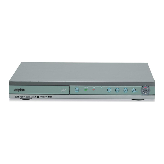
DVD Video Player
FWD
FILE NO.
DVD-SL40
(AU)
PRODUCT CODE No.
137 123 07
SM
REFERENCE No.
5810576
Advertisement
Table of Contents

Related Manuals for Sanyo DVD-SL40


Summary of Contents for Sanyo DVD-SL40
-
Page 1: Table Of Contents
FILE NO. DVD-SL40 DVD Video Player Service Manual (AU) AUDIO SUBTITLE OPEN/CLOSE RANDOM ZOOM ANGLE REPEAT A-B REPEAT RETURN TOP MENU MENU SETUP ON SCREEN SLOW SEARCH MODE PAUSE/STEP PREV NEXT PLAY PROGRAM REMOTE CONTROLLER RB-SL40 PRODUCT CODE No. CONTENTS 137 123 07 DVD Mechanism Replacement .......... -
Page 2: Dvd Mechanism Replacement
DVD MECHANISM REPLACEMENT 1. Cautionary instructions in handling the assy Do not connect or disconnect roughly by an excessively strong (Safety instructions) force, or a broken wire or bad contact may result. Optical pickup Semiconductors are connected. Do not touch connector terminals The laser beam used in the pickup is classified as "class 2". -
Page 3: Mechanism Replacement
MECHANISM REPLACEMENT 1. How to Remove DVD Mechanism Side of DVD mechanism First, it is necessary to remove Escutcheon. Front Rear Cylindrical thing How to remove Escutcheon. An eject button is pushed and a tray is taken out. Please remove Escutcheon, as shown in the left figure 2 . When an eject button 1 does not function. -
Page 4: How To Load Software For Main P.w.board
MECHANISM REPLACEMENT 4. Tray parts. 5. Base mechanism mounting parts. G-SANKOL G-SANKOL : Clean the groove by alcohol well. HOW TO LOAD SOFTWARE FOR MAIN P.W.BOARD 1. Power on, then open tray. 2. It take on CD-ROM (Part code is "0PRADC7123--A") for UPDATE software to the tray, and tray close. 3. -
Page 5: Sevice Mode
SERVICE MODE A. Market / Region SETUP In the initial condition for this model, Market and Region information are undefined. MARKET MARKET MARKET In the following cases, be sure to set up Market/Region. 1. When updating the system using CD-R REGION REGION REGION... -
Page 6: Exploded View (Cabinet & Chassis)
EXPLODED VIEW (CABINET & CHASSIS) - 5 -... -
Page 7: Parts List
645 068 7358 ASSY DVD DOOR CN001 645 064 0438 24P CONNECTOR 645 067 9605 DOOR LENS CN501 645 067 9230 11P CONNECTOR 645 064 0674 LOGO,SANYO CN504 645 063 2433 4P CONNECTOR 645 068 7457 DVD DOOR CN505 645 063 2440 5P CONNECTOR... - Page 8 PARTS LIST REF.NO. PART NO. DESCRIPTION REF.NO. PART NO. DESCRIPTION FB105 645 067 9223 INDUCTOR 1UH 10% RN005 645 067 9254 RESISTOR,RES ARRAY FB106 645 067 9223 INDUCTOR 1UH 10% RN006 645 064 0339 RESISTOR,RES ARRAY FB121 645 067 9223 INDUCTOR 1UH 10% RN007 645 064 0339 RESISTOR,RES ARRAY FB301...
-
Page 9: Exploded View (Dvd Mechanism)
EXPLODED VIEW (DVD MECHANISM) DM15 DM01 DM16 DM02 DM18 DM15 DM05 DM15 DM03 DM16 DM16 DM06 DM04 DM19 DM07 DM08 DM18 DM21 DM19 DM09 DM10 DM20 DM12 DM11 DM13 DM14 PARTS LIST REF.NO. PART NO. DESCRIPTION DVD DECK MECHANISM CHASSIS DM20 614 329 6324 MOUNTING, REF.NO. -
Page 10: Ic Block Diagram & Description
IC BLOCK DIAGRAM & DESCRIPTION IC001 IMP809SEUR-T (Reset) IC004 RC4558 (Ope. Amp.) 1OUT 1IN- 2OUT IMP809 (IMP810) 1IN+ 2IN- 2IN+ (RESET) RESET IC005,IC114,115 B1117N-2.85 (Regulator) SOT - 223 SOT - 223 Tab V Tab V Adj/GND Adj/GND Fr ont View Fr ont View IC101 KA5M02659RN (Power Switch) DRAIN... - Page 11 IC BLOCK DIAGRAM & DESCRIPTION IC102 SFH615A-3 (Opt. Sensor) IC201 TL431 (Regulator) (Top view) Cathode Anode Reference Anode Collector Cathode Emitter IC103 MBM29LV800BA ( Flash) IC104 AT24C02N-10SI-2.7 (EEPROM) START STOP LOGIC SERIAL H,V. PUMP/TIMING CONTROL LOGIC LOAD COMP DATA RECOVERY DEVICE ADDRESS LOAD...
- Page 12 IC BLOCK DIAGRAM & DESCRIPTION IC106 4MX16Y3VTW,SD41620HGT-6, K4S641632H-UC(L)7 (SDRAM) IC110 BA5954 (4 ch.motor driver) - 11 -...
- Page 13 IC BLOCK DIAGRAM & DESCRIPTION IC109 WM8761ED (Stereo DAC) 10 12 CONTROL INTERFACE SIGMA PASS 6 VOUTR DELTA MUTE FILTER MODULATOR BCKIN AUDIO DIGITAL FILTERS LRCIN INTERFACE SIGMA MUTE PASS 9 VOUTL DELTA FILTER MODULATOR NAME TYPE DESCRIPTION LRCIN Digital input Sample rate clock input Digital input Serial audio data input...
-
Page 14: Block Diagram
BLOCK DIAGRAM - 13 -...