Table of Contents
Advertisement
Quick Links
Service
Manual
This manual is to be used by qualified appliance technicians only. Viking
does not assume any responsibility for property damage or personal
injury for improper service procedures done by an unqualified person.
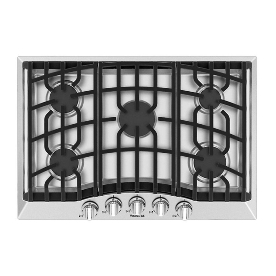
D3 Gas
Cooktops
Preferred Service
This Base Manual covers general and
specific information including, but not
limited to the following models:
RDGSU2005BSB
RDGSU2065BSB
®
SMC-0026
JUNE 2012
Advertisement
Table of Contents

Summary of Contents for Viking RDGSU2005BSB
- Page 1 Service ® Preferred Service Manual This manual is to be used by qualified appliance technicians only. Viking does not assume any responsibility for property damage or personal injury for improper service procedures done by an unqualified person. D3 Gas This Base Manual covers general and...
-
Page 2: Table Of Contents
Iris Spark Module removal ........14 Gas valve removal ..........15 Troubleshooting ............16 Iris Spark Module ........... 16 Single Spark Module ..........16 Igniter ..............17 Dual gas valve switch ..........17 Schematic ..............18 Wiring Diagram ............. 19 ©2012 Viking Preferred Service... -
Page 3: Important Information
Always read and obey all safety messages. This is the safety alert symbol. CAUTION VIKING will not be responsible for any injury or property damage from improper service procedures. This symbol alerts you to hazards that can kill If performing service on your own product, you must or hurt you and others. -
Page 4: Warnings
BURN OR ELECTRICAL SHOCK HAZARD the vicinity of this or any appliance. To avoid risk of injury or death, make sure all controls are OFF and COOL before cleaning. Failure to do so can result in burns or electrical shock ©2012 Viking Preferred Service... -
Page 5: General Information
• In Massachusetts: A "T" handle type NOTE: If electrical power is not supplied or manual gas valve must be installed in is interupted, the burners will have to be lit gas supply line to the appliance. manually with a match. ©2012 Viking Preferred Service... -
Page 6: Gas Requirements (Continued)
IMPORTANT: NEVER reuse old connectors 3. To shutdown the burner, turn knob when installing this cooktop. clockwise to the OFF position. In case of failure, shut the gas OFF using the installer supplied manual shut-off valve. ©2012 Viking Preferred Service... -
Page 7: Model / Serial Tag Location
200 = 30” Wide 260 = 36” Wide Cook Top Serial Number Breakdown 05 10 12 C00036178 Month Serial Number Year of Manufacture Model / Serial tag is located underneath cooktop next to gas inlet line. ©2012 Viking Preferred Service... -
Page 8: Operation
flame size. Setting the proper flame height for the desired cooking process and selecting the correct cooking vessel will result in superior cooking performance, while also saving time and energy. ©2012 Viking Preferred Service... -
Page 9: Removal Of Stainless Steel Top
4. Remove the two screws from each burner as shown in illustration below. 5. After removing these ten phillips head screws, lift stainless steel top off of cooktop and place in a secure area to prevent damage to top and customer's home. ©2012 Viking Preferred Service... -
Page 10: Burner Box Components
Left Front Right Front Burner Base Burner Base Left Front Left Rear Dual Center Right Rear Right Front Valve & Spark Valve & Spark Valve w/ Valve & Spark Valve & Spark Module Module Switch Module Module ©2012 Viking Preferred Service... -
Page 11: Burner Base Removal
3. Remove Stainless steel top, see Page 9 for procedure. 4. Remove gas line connection from both burner bases, see photo below. 5. With gas lines disconnected, remove bracket bolts from underneath cooktop burner box. ©2012 Viking Preferred Service... - Page 12 8. If you are replacing the burner base you will have to transfer the orfice spud, igniter and clip to the new base, see appropriate sections to accomplish their removal. ©2012 Viking Preferred Service...
-
Page 13: Igniter Removal
4. Once clip is removed, igniter will slide out of slot where clip was previously locked into. Burner Base View from underneath Remove orfice spud burner base with socket and ratchet with clip and igniter still installed. ©2012 Viking Preferred Service... -
Page 14: Iris Spark Module Removal
Iris spark module. Top view of gas valve Arrows show bolt heads that Iris spark module snaps on to. Bottom view of Iris spark module 4. Lift Iris spark module straight up and off of gas valve ©2012 Viking Preferred Service... -
Page 15: Gas Valve Removal
Disconnect line and pull away from valve being careful not to damage line or valve. ©2012 Viking Preferred Service... -
Page 16: Troubleshooting
Neutral Input module after verifying igniter and wire to Top lug igniter are good. L1 Input Bottom lug Ground 120 VAC (Black) Neutral (White) Ground (Green) Output to Igniter ©2012 Viking Preferred Service... -
Page 17: Igniter
The other ohmmeter lead goes to the tip of the igniter. 2. If the ohmeter reading is incorrect isolate the issue to the wire or the igniter. ©2012 Viking Preferred Service... -
Page 18: Schematic
Wiring Diagrams ©2012 Viking Preferred Service... -
Page 19: Wiring Diagram
Wiring Diagrams ©2012 Viking Preferred Service...


