Advertisement
Quick Links
See also:
Owner's Manual
Performance Specifications ..........................................2
Notes ...........................................................................2
Rear Panel ...................................................................3
Section Location ..........................................................4
Block Diagram .......................................................5 - 6
Interconnection Diagram ........................................7 - 8
Heatsink Schematic and PCB ................................9 - 10
Heatsink Slave Schematic and PCB .....................11 - 12
Driver Schematic and PCB..................................13 - 15
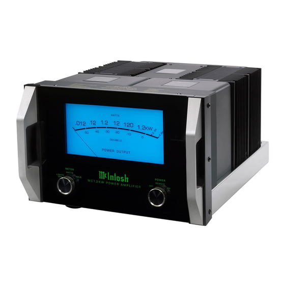
MC1.2KW
POWER AMPLIFIER
SERIAL NO. YF1001 And Above
CONTENTS
SERVICE MANUAL
Input Schematic and PCB ..........................................16
Capacitor Schematic and PCB ............................17 - 18
Meter Schematic and PCB ..................................19 - 22
Lamp Schematic and PCB ...................................23 - 24
Light Schematic and PCB ...........................................25
Power Guard Schematic and PCB ..............................26
Parts List .............................................................29 - 32
Repacking Instruction ................................................33
MC1.2KW
Advertisement

Related Manuals for McIntosh MC1.2KW


Summary of Contents for McIntosh MC1.2KW
- Page 1 MC1.2KW MC1.2KW POWER AMPLIFIER SERIAL NO. YF1001 And Above CONTENTS Performance Specifications ..........2 Input Schematic and PCB ..........16 Notes ................2 Capacitor Schematic and PCB ......17 - 18 Rear Panel ..............3 Meter Schematic and PCB ........19 - 22 Section Location ............4 Lamp Schematic and PCB ........23 - 24...
-
Page 2: Performance Specifications
0.005% maximum harmonic distortion at any power level 240 Volts, 50/60Hz at 6.5 Amps from 250 milliwatts to rated power, 20Hz to 20,000Hz Standby: 0.5 watts Note: Refer to the rear panel of the MC1.2KW for the Dynamic Headroom correct voltage. Overall Dimensions Frequency Response Width is 17-3/4 inches (45.09cm) -
Page 3: Rear Panel
MC1.2KW REAR PANEL... -
Page 4: Section Location
SECTION LOCATIONS TOP VIEW WITH COVER REMOVED BOTTOM VIEW WITH COVER REMOVED... -
Page 5: Block Diagram
MC1.2KW BLOCK DIAGRAM... - Page 6 INTERCONNECT...
- Page 7 MC1.2KW 2A 2B HEATSINK MASTER 749485 SCH and PCB BIAS ADJUSTMENT OPERATE THE AMPLIFIER FOR 5 MINUTES WITH NO INPUT SIGNAL. HEATSINKS MUST BE COOL. ADJUST R13 FOR 18+ _ 2mV ACROSS PINS 1 & 2 OF J4. ADJUST BOTH MASTER...
- Page 8 3A 3B HEATSINK SLAVE 749487 SCH and PCB...
- Page 9 MC1.2KW DRIVER 750760 SCH 47 .5 W -72V -72VR J1-1 J3:7 72VR 47 .5 W 72VR J1-6 J3:2 72VR J1-2 J3:6 72VR METER LIGHT CONTROL J6:2 1.74V +DRIVE A J1-10 70.3V J1-5 J3:3 70.3V METER LIGHT 70.3V 70.3V CONTROL J7:10 J1-1 69.7V...
- Page 10 DRIVER INPUT 750760 PCB 750753 SCH and PCB R152 J7:7 J7-4 R154 J7:6 -11V -11V -11V J7-5 R153 J7:3 J7-8 METER LIGHT J7:1 CONTROL J7-10 R100 J7:2 J7-9 -11V U1:1 -11V -11V 10uF J7:4 INPUT+ J7-7 10uF J7:5 INPUT- J7-6 22pF R131 R142...
- Page 11 MC1.2KW CAPACITOR 749367 SCH and PCB...
- Page 12 METER POWER SUPPLY 750752 SCH 1 of 2 -12V 1.82k 200k METER V- 22.1k J1:2 J6-10 4.99k RECTIFIER U2:1 22.1k 22.1k METER V+ J1:1 J6-11 U2:2 -.65V -.5V VOLTAGE DC AMP U3:1 LOG AMP -12V HOLD METER CALIBRATION METER + MT1+ J3:1 J3:2...
- Page 13 MC1.2KW METER POWER SUPPLY 750752 SCH 2 of 2 and PCB 5V REG. J1:6 J6-6 IN OUT J1:8 J6-4 10VAC T1/BRN J1:7 -12V J6-5 TURN J1:9 T1/BRN J6-3 IN OUT J2:6 J1-6 129860 Rev.A RoHS J2:2 PANEL LED J1-2 -20V...
- Page 14 LAMP 750759 SCH and PCB 47.5 47.5 BLUE METER LED J1:1 J2:1 COLOR J1:2 PANEL LED LOGO J2:2 J1:3 PG LED PG_LIGHT J2:3 COLOR BRIGHTNESS COLOR BRIGHTNESS BRIGHTNESS GREEN J1:4 J2:4 J1:5 -12V -12V J2:5 47.5 47.5 BLUE J1:6 J2:6 COLOR 129862A Rev.A...
- Page 15 MC1.2KW POWER GUARD LIGHT 750759 SCH and PCB 750759 SCH and PCB J5:1 LOGO1+ J2:1 J5:2 STBY LED STBY LED J2:2 J7:1 J8:1 PG LIGHT CATHODE CATHODE J4:1 J10-4 LOGO1- J5:3 J2:3 J7:2 J8:2 J4:2 J7:3 J8:3 J4:3 STBY LED...
- Page 16 NOTES...
-
Page 17: Parts List
MC1.2KW PARTS LIST Ref. No. Description Part No. RES MET OX 680 OHM 5% 1/2W 137099 RES MF 22.1K 1% 1/4W 144564 RES MET OX 1.8K 5% 1/2W 137100 INTERCONNECT RES MET OX 430 OHM 5% 1/2W 137101 Ref. No. - Page 18 PARTS LIST con’t Ref. No. Description Part No. TRANSISTOR PNP 2SA1321C 132326 TRANSISTOR PNP 2SA1321C 132326 TRANSISTOR NPN 2SC3334C 132325 750760 DRIVER PCB Ref. No. Description Part No. TRANSISTOR NPN 2SC3334C 132325 TRANSISTOR SI NPN 132254 CAP MONO .1UF 50V 20% 061346 TRANSISTOR PNP 132255...
- Page 19 MC1.2KW PARTS LIST con’t Ref. No. Description Part No. CONN HEADER 2 PIN 0.156 117404 CONN HEADER 2 PIN 0.156 117404 CONN HEADER 2 PIN 0.156 117404 750760 DRIVER PCB Con’t CONN HEADER 2 PIN 0.156 117404 Ref. No. Description Part No.
- Page 20 PARTS LIST con’t Ref. No. Description Part No. RES MF 1.82K 1% 1/4W 144582 RES MF 475K 1% 1/4W 144604 RES MF 324 OHM 1% 1/4W 144597 750752 METER POWER SUPPLY PCB Con’t TRANSFORMER CURRENT 159353 Ref. No. Description Part No. SCR TT 6-32 X 1/4 PH PN BLK 401054 TRANSISTOR PNP SILICON...
-
Page 21: Repacking Instruction
MC1.2KW REPACKING INSTRUCTIONS Quantity Part Number Description 034105 Shipping carton top 034104 Shipping carton bottom 034349 Foam Pad (top and bottom) 034350 Foam Ring 400159 10-32 x 3/4 inch screw 018445 Feet 018445 Feet... - Page 22 The continuous improvement of its products is the policy of McIntosh Laboratory Incorporated, who reserve the right to improve design without notice. Because of the constant upgrading of McIntosh products’ circuitry and components, the Company cannot insure, and does not warrant, the accuracy of the within schematic material, which is intended for information only.