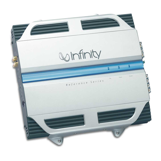
Summary of Contents for Infinity 7520a
-
Page 1: Channel Power Amplifier
Reference Series 7520a 7521a 2 CHANNEL POWER AMPLIFIER SERVICE MANUAL Infinity Systems, Inc. 250 Crossways Park Dr. Woodbury, New York 11797 Rev3aa10/2005... -
Page 2: Table Of Contents
(L x W x D) (305mm x 290mm x 68mm) Fuse: Infinity continually strives to update and improve existing products, as well as create new ones. The specifications and details in this and related JBL publications are therefore subject to change without notice. -
Page 3: Features/Test Conditions
Reference 7520a/7521a... -
Page 4: Controls/Connections
HIGH-LEVEL INPUT CONNECTIONS within 18" of the battery terminal. Do not The 7520a/7521a amplifiers are install the fuse at this time. Route the wire to equipped with speaker-level inputs that allow the amplifier’s location, and connect it to the you to add an amplifier to head units that do amplifier’s positive (+12V) terminal. - Page 5 Reference 7520a/7521a Power Amplifier – 7520a/7521a PPLICATIONS This amplifier can be set up for stereo or bridged-mono operation, as shown in Figures 5 and 6. NOTE: For simplicity, Figures 5 and 6 do not show power, remote and input connections.
-
Page 6: Installation
If using the 7520a/7521a to drive a subwoofer(s), LP: Allows bass to pass through to the speakers; set the crossover mode to LP (low pass). -
Page 7: Basic Troubleshooting
Reference 7520a/7521a Power Amplifier ROUBLESHOOTING • PROBLEM: • PROBLEM: No audio (POWER LED is off). No audio (PROTECT LED is on). CAUSE and SOLUTION: CAUSE and SOLUTION: No voltage at BATT+ and/or REM terminals, or Voltage greater than 16V or less than 8.5V on bad or no ground connection. -
Page 8: Typical System Wiring
Reference 7520a/7521a... -
Page 9: Exploded View/Parts List
Reference 7520a/7521a... -
Page 10: Mechanical Parts List
Reference 7520a/7521a Power Amplifier Mechanical Parts List... -
Page 11: Amplifier Block Diagram
Reference 7520a/7521a Power Amplifier REF 7520a/7521a BLOCK DIAGRAM... -
Page 12: Drawings
Reference 7520a/7521a TER02 V-CUT FH01 TM0006-01 TM0009-01 TER01 7.5m/m WF-9402P 7.5m/m 7.5m/m 7.5m/m J335 C3198GR 10m/m J336 10m/m 8.2K 680/2W 680/2W 7.5m/m C3198GR J315 C801 A1266GR 7.5m/m R262 R162 J316 473P 7.5m/m R261 4.7/0.5W 3.9K J317 4.7/0.5W R90 47K 1N5404... - Page 13 Reference 7520a/7521a V - C U T RCA101 R295 VR103 SW101 SW102 R222 R101 HI01 R201 VR101 C228 R196 C128 C223 C224 C102 C103 C202 C203 J138 J128 J150 C255 C155 R128 J137 J129 R206 R107 VR102 J141 R126 R155...
- Page 14 Reference 7520a/7521a...
-
Page 15: Electrical Parts List
Reference 7520a/7521a Electrical Parts List PART NO NOMENCATURE DESCRIPTION MFR PARTS REF NO Q'TY TRS-00-00087 TRANSISTOR SMALL SIGNAL PNP KTA1023Y Q01,144,244 TRS-00-00088 TRANSISTOR SMALL SIGNAL NPN KTC1027Y Q134,234 TRS-00-00091 TRANSISTOR SMALL SIGNAL PNP KTA1268GR TRS-00-00111 TRANSISTOR SMALL SIGNAL NPN KTC3200GR... - Page 16 Reference 7520a/7521a Electrical Parts List cont'd PART NO NOMENCATURE DESCRIPTION MFR PARTS REF NO Q'TY ELC-00-00198 CAPACITOR ELECTROLYTIC "SMS" 47/16V C11,14 ELC-00-00205 CAPACITOR ELECTROLYTIC "SMS" 47/25V ELC-00-00227 CAPACITOR ELECTROLYTIC "SMS" 47/50V C57,67 ELC-00-00199 CAPACITOR ELECTROLYTIC "SMS" 100/16V C12,13,17,171,181,271 ELC-00-00200 CAPACITOR ELECTROLYTIC "SMS"...
- Page 17 Reference 7520a/7521a Electrical Parts List cont'd PART NO NOMENCATURE DESCRIPTION MFR PARTS REF NO Q'TY THS-00-00013 THERMISTOR 50K NTC RESISTOR FTD5-350 TH01 ELC-00-00183 CAPACITOR ELECTROLYTIC "SHL" 1000/35V (12.5x20m/m) C51,61 ELC-00-00603 CAPACITOR ELECTROLYTIC "SHL" 3300/35V (18x25m/m) C52,62 ELC-00-00727 CAPACITOR ELECTROLYTIC "WL"...
- Page 18 Reference 7520a/7521a Reference 7521a Electrical Parts List Addendum The following chart below represents the only electrical parts differences in 7520a and 7521a models: MODEL PART NAME PART NUMBER SPEC DESIGNATOR REF 7520a RESISTOR RES-00-00577 1/5WF 750 OHM R108,208 REF 7521a...
-
Page 19: Ic/Transistor Pinouts
Reference 7520a/7521a... - Page 20 Reference 7520a/7521a...
-
Page 21: Ref 7520A Schematics
B+SW 14.4V 13.57V 13.66V A1023Y FH01 10/0.5W CL-300 12.93V 1N5404 430K 105M C800 4.7K 10/16V N4004 4.7K C3198GR C801 8.2K 473P 4.44V 10.5KF 33.7V FR154 VCC2 4.7KF 104P 47/50V FR154 FR154 -33.7V 47/50V FR154 5.09V VEE2 FQP50N06 13.57V 5T:12T 33.7V (0.7x9):(0.7x4) YG225D2 CL-500... - Page 22 C126 R126 R125 +15V 33.7V 10KF 10KF R191 VCC2 33.7V 330/2W R-OUT C128 R128 RCA101-C 4.7/50V D191 R131 C200 DJB-554A C400 C192 C191 1N4744(15V) R135 R136 473P 473P 330/16V 220/16V U111-A 32.8V C131 R127 R132 Q133 NJM2068LD 2.2/50V R129 A1266GR 5.6K -15V 100K...
-
Page 23: Ref 7521A Schematics
Power Amplifier Reference 7521a REF 7521a SCHEMATIC PAGE 1 B+SW A1023Y FH01 CL-300 10/0.5W 1N5404 430K 105M C800 10/16V 4.7K N4004 4.7K C3198GR C801 8.2K 473P 10.5KF FR154 VCC2 4.7KF 104P 47/50V FR154 FR154 47/50V FR154 VEE2 FQP50N06 5T:12T (0.7x9):(0.7x4) YG225D2 CL-500 473P... - Page 24 Power Amplifier Reference 7521a REF 7521a SCHEMATIC PAGE 2 C126 R126 R125 +15V 10KF 10KF R191 VCC2 330/2W R-OUT C128 R128 RCA101-C 4.7/50V D191 R131 C200 DJB-554A C400 C192 C191 1N4744(15V) R135 R136 473P 473P 330/16V 220/16V U111-A C131 R127 R132 Q133 NJM2068LD...


