Table of Contents
Advertisement
Quick Links
Download this manual
See also:
Installation Manual
Networking System for UHF Wireless Microphones
Système de gestion de réseau pour microphones sans fil UHF
Sistema de conexión en red para micrófonos inalámbricos UHF
Sistema di collegamento in rete per radiomicrofoni UHF
1997, Shure Brothers Incorporated
27A8623 (QL)
NETWORKING INTERFACE SYSTEM
with Software Interface for Microsoft Windows
Netzwerksystem für drahtlose UHF–Mikrofone
mit Softwareschnittstelle für Microsoft Windows
avec interface logicielle pour Microsoft Windows
con interfase de software para Microsoft Windows
con interfaccia
Shure Brothers Incorporated
222 Hartrey Avenue
Evanston IL 60202-3696 U.S.A.
Model UA888 User Guide
software per Microsoft Windows
UHF
POWER
LINK
UA888
Printed in U.S.A.
Advertisement
Table of Contents

Related Manuals for Shure ua888


Summary of Contents for Shure ua888
- Page 1 Shure Brothers Incorporated 222 Hartrey Avenue Evanston IL 60202-3696 U.S.A. Model UA888 User Guide NETWORKING INTERFACE SYSTEM POWER LINK UA888 Networking System for UHF Wireless Microphones with Software Interface for Microsoft Windows Netzwerksystem für drahtlose UHF–Mikrofone mit Softwareschnittstelle für Microsoft Windows Système de gestion de réseau pour microphones sans fil UHF...
-
Page 2: Table Of Contents
Trademark Notification: Shure is a registered trademark of Shure Brothers Incorporated. Shure Link is a trademark of Shure Brothers Incorporated. IBM is a registered trademark of International Business Ma- chines Corporation. Microsoft and PowerPoint are registered trademarks of Microsoft Corporation. PC Paintbrush is a registered trademark of ZSoft Corporation. -
Page 3: Introduction
INTRODUCTION The Shure UA888 Networking Interface System lets you use a computer to monitor and control up to 32 Shure UHF Wireless receivers from a remote site. The UA888 system is designed for installed sound reinforcement applications, including theater, larger houses of worship; touring sound systems; and audio/video rental ap- plications. -
Page 4: Ua888 Interface Module Connectors And Controls
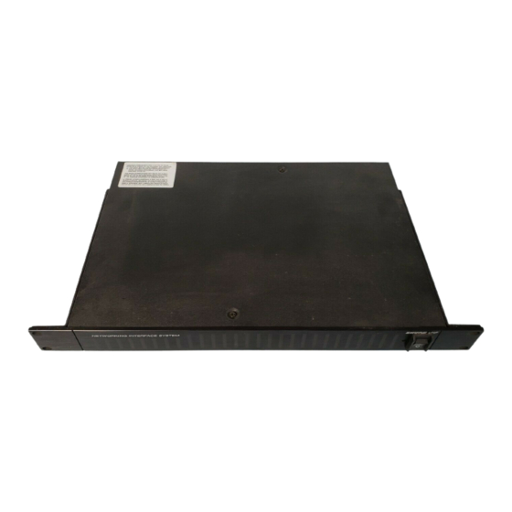
UA888 Interface Module Connectors and Controls Front Panel The front panel of the UA888 Interface Module, shown in Figure 1, includes the following controls and indicators: NETWORKING INTERFACE SYSTEM POWER UA888 INTERFACE MODULE FONT PANEL FIGURE 1 1. Power On LED. This LED glows green when the UA888 Interface Module is turned on. -
Page 5: Installation
2. Using the supplied 1 meter (3 ft.) cable, connect the 25-pin D connector labeled “Receiver A” on the rear panel of the UA888 to the 25-pin D connector on the rear panel of a U4 receiver. See Figure 3. -
Page 6: Installing Ua888 Software
3. Connect the Shure Link OUT port of the second UA888 to the Shure Link IN port of the third UA888. 4. Connect the Shure Link OUT on the last UA888 to the Shure Link IN on the first UA888. This creates a communication loop between all networked UA888 Interface Modules and the computer. -
Page 7: Connecting The Ua888 System To A Sound System
Simply connect the 25-pin D Network Interface con- nector on the rear panel of each U4 Receiver to one of the 25-pin D connectors on the rear panel of the UA888 Interface Module, using the supplied cable. A typical sound system incorporating the UA888 Networking Sys- tem is shown in Figure 7. -
Page 8: Using The Ua888 System
1. Turn on the computer, the UA888 Interface Module, and the U4 Receivers. 2. Go to the main menu on the computer display and double click on the UA888 icon, shown in Figure 8. If the system is linked to the computer via COM Port 1, it will automatically establish a software connection and detect any connected receivers. -
Page 9: Connecting The Software
2. When the window shown in Figure 11 appears, click on the COM port you wish to use. The default setting is COM 1. COM PORT SELECTION WINDOW FIGURE 11 3. Click on the “OK” button to activate your selection or click on “Cancel” and make a new selection. Connecting the Software To connect the program for any reason after it has been opened, proceed as follows: 1. -
Page 10: Enlarging Receiver Display Icons
2. Drag the display to a square on the left side of the display and release the mouse button. Repeat this procedure for each receiver display you wish to enlarge. Refer to Figure 14. As you move each icon, a box will appear with that receiver’s I.D. number, UA888 port designation, and channel number. ENLARGED RECEIVER DISPLAY ICONS... -
Page 11: Changing The Receiver Settings
Changing the Receiver Settings To change receiver parameters such as Name, Label, Squelch Level, Group, Channel, and Frequency, pro- ceed as follows: 1. Double click on the icon of the receiver you wish to change. The window shown in Figure 15 will appear. RECEIVER CONTROL WINDOW FIGURE 15 2. -
Page 12: Saving Scene Files
3. When the window shown in Figure 17 appears, click on the color block next to the element you wish to change. ICON COLOR MODIFICATION WINDOW FIGURE 17 4. When the window shown in Figure 18 appears, click on the desired new color, then click on the “OK’ button. ICON COLOR PALETTE FIGURE 18 Saving Scene Files... -
Page 13: Retrieving Scene Files
SELECTING THE “SAVE SCENE AS..” FUNCTION FIGURE 20 NOTE: The UA888 software will only save settings for version 2.0 or later receivers. If your sound system includes earlier versions of the receivers, they will not appear in the saved scene. -
Page 14: Deleting Scene Files
1. Exit the UA888 program by clicking on the “File” heading on the main menu bar and selecting “Exit.” 2. Open the file manager window and scroll to the drive containing the UA888 directory. -
Page 15: Scanning For Uhf Frequencies
“WALK AROUND” PLOTTER WINDOW FIGURE 25 3. Click on the arrow next to the “Walk Around Time” field and scroll to the length of time the test is to run (maximum setting is 1 hour). NOTE: To determine the time of any point on the graph, simply move the cursor to the point and click on it. The time will be displayed in a pop up window. - Page 16 2. When the UHF Scanner window appears, as shown in Figure 27, click on the arrow next to the “Select Receiver to Scan” field and scroll to the receiver you wish to test. 3. Click on the “Start” button. The system will automatically begin scanning for rf signals within the receiver’s operating bandwidth.
-
Page 17: Installing Password Protection
Password Protection,” as shown in Figure 28. Then release the mouse button. SELECTING THE PASSWORD FUNCTION FIGURE 28 2. When the “Activate Password Protection?” window appears, as shown in Figure 29, click on “Yes.” NOTE: The default password is “ua888.” PASSWORD ACTIVATION WINDOW FIGURE 29 Changing the Password To change the system password, proceed as follows: 1. -
Page 18: Removing Password Protection
Exiting the Program To exit the UA888 program, pull down the “File” menu from the main menu bar, select “Exit,” then release the mouse button. See Figure 32. You will automatically exit the UA888 program and return to the file manager. -
Page 19: Troubleshooting
It is extremely unlikely that both meters would fail simultaneously on multliple receivers. However, the accura- cy of the U4 meters can be temporarily affected if the UA888 is turned off while the receivers are still on. Turn the UA888 Interface Module back on and leave it on. -
Page 20: Specifications
Consult your dealer or an experienced radio/TV technician for help. NOTE: Do not use cables longer than 3.1 m (10 ft.) to connect the UA888 Interface Module to a U4 receiver. Under extremely abnormal conditions, electri- cal transients on the power line may interrupt communication between the UA888 Interface Module and the computer. -
Page 21: Appendix A. Rack Mounting The Ua888
To mount the UA888 Interface Module in a 19-inch audio equipment rack, proceed as follow: 1. Insert the UA888 network module into the rack. 2. Using the supplied screws, secure the UA888 network module to the rack, as shown below. NOTE: For more information on rack mounting, call Shure Customer Service at 1–800–25–SHURE. Outside the U.S.A. - Page 22 – 21 – ENGLISH...
-
Page 23: Appendix B. Cable Connector Pin Maps
16 18 20 22 24 TO COMPUTER 17 19 21 23 25 COMPUTER 25-PIN RS-232 CONNECTOR (MALE) –– 9-PIN MALE RS-232 CONNECTOR FEMALE Shure Link Cable — 5-Pin DIN Cable (MIDI-compatible cable) FUNCTION PIN # –– DATA SHIELD DATA SHURE LINK IN ––... - Page 24 11 9 7 10 12 25-PIN FEMALE 16 18 20 22 24 TO UA888 17 19 21 23 25 UA888 25-PIN RS-232 CONNECTOR (MALE) 11 9 7 10 12 18 20 22 24 25-PIN MALE 17 19 21 23 25...