Table of Contents
Advertisement
Available languages
Available languages
Quick Links
Advertisement
Table of Contents

Related Manuals for Asus A88XM GAMING


Summary of Contents for Asus A88XM GAMING
- Page 1 Preface A88XM GAMING Motherboard G52-79031X2...
-
Page 2: Copyright Notice
Copyright Notice The material in this document is the intellectual property of MICRO-STAR INTERNATIONAL. We take every care in the preparation of this document, but no guarantee is given as to the correctness of its contents. Our products are under continual improvement and we reserve the right to make changes without notice. -
Page 3: Technical Support
Smartphone Application is a smart web gadget that works as a shopping navigator and provides specs comparison for IT buyers. With a simple tap of the smartphone, you'll efficiently locate your ideal products from a wide variety of choices and, if product details are required, you may easily download user manuals within minutes. -
Page 4: Safety Instructions
Safety Instructions ■ Always read the safety instructions carefully. ■ Keep this User’s Manual for future reference. ■ Keep this equipment away from humidity. ■ Lay this equipment on a reliable flat surface before setting it up. ■ The openings on the enclosure are for air convection hence protects the equipment from overheating. - Page 5 FCC-B Radio Frequency Interference Statement This equipment has been tested and found to comply with the limits for a Class B digital device, pursuant to Part 15 of the FCC Rules. These limits are designed to provide reasonable protection against harmful interference in a residential installation. This equipment generates, uses and can radiate radio frequency energy and, if not installed and used in accordance with the instructions, may cause harmful interference to radio communications.
- Page 6 Radiation Exposure Statement This equipment complies with FCC radiation exposure limits set forth for an uncontrolled environment. This equipment and its antenna should be installed and operated with minimum distance 20 cm between the radiator and your body. This equipment and its antenna must not be co-located or operating in conjunction with any other antenna or transmitter.
-
Page 7: Battery Information
Battery Information European Union: Batteries, battery packs, and accumulators should not be disposed of as unsorted household waste. Please use the public collection system to return, recycle, or treat them in compliance with the local regulations. Taiwan: For better environmental protection, waste batteries should be collected separately for recycling or special disposal. - Page 8 WEEE (Waste Electrical and Electronic Equipment) Statement ENGLISH To protect the global environment and as an environmentalist, MSI must remind you that... Under the European Union (“EU”) Directive on Waste Electrical and Electronic Equipment, Directive 2002/96/EC, which takes effect on August 13, 2005, products of “electrical and electronic equipment”...
- Page 9 ESPAÑOL MSI como empresa comprometida con la protección del medio ambiente, recomienda: Bajo la directiva 2002/96/EC de la Unión Europea en materia de desechos y/o equipos electrónicos, con fecha de rigor desde el 13 de agosto de 2005, los productos clasificados como “eléctricos y equipos electrónicos”...
- Page 10 TÜRKÇE Çevreci özelliğiyle bilinen MSI dünyada çevreyi korumak için hatırlatır: Avrupa Birliği (AB) Kararnamesi Elektrik ve Elektronik Malzeme Atığı, 2002/96/EC Kararnamesi altında 13 Ağustos 2005 tarihinden itibaren geçerli olmak üzere, elektrikli ve elektronik malzemeler diğer atıklar gibi çöpe atılamayacak ve bu elektonik cihazların üreticileri, cihazların kullanım süreleri bittikten sonra ürünleri geri toplamakla yükümlü...
-
Page 11: Table Of Contents
CONTENTS ▍ English ...................... En-1 Motherboard Specifications ................En-2 Connectors Quick Guide ..................En-5 Back Panel Quick Guide ..................En-7 APU (Accelerated Processing Units) ..............En-9 Memory ......................En-12 Mounting Screw Holes ..................En-13 Power Supply ....................En-14 Expansion Slots ....................En-15 Video/ Graphics Cards ..................En-16 Internal Connectors ..................En-17 Jumper ......................En-23 Buttons &... - Page 12 Connecteurs d’alimentation ................Fr-14 Emplacements d’extension ................Fr-15 Cartes Vidéo/ Graphiques ................Fr-16 Connecteurs internes ..................Fr-17 Cavaliers ......................Fr-23 Boutons & Interrupteurs ..................Fr-24 Indicateurs d'état LED ..................Fr-27 Pilotes et Utilitaires ....................Fr-28 Configuration BIOS ...................Fr-29 Русский ....................Ru-1 Характеристики материнской платы .............. Ru-2 Краткое руководство по разъемам ..............Ru-5 Разъемы...
-
Page 13: English
English Thank you for choosing the A88XM GAMING Series (MS-7903 v1.X) M-ATX motherboard. The A88XM GAMING Series motherboards are based on AMD ® A88X chipset for optimal system efficiency. Designed to fit the advanced FM2+/ FM2 processor, the A88XM GAMING Series motherboards ®... -
Page 14: Motherboard Specifications
Motherboard Specifications ■ AMD Socket FM2+/ FM2 A-Series/Athlon™ Processors Support Chipset ■ AMD A88X Memory ■ 4x DDR3 memory slots supporting up to 32GB ■ Supports DDR3 2400 (OC)/ 2133/ 1866/ 1600/ 1333 MHz Support ■ Dual channel memory architecture ■... - Page 15 Back Panel ■ 1x PS/2 keyboard/ mouse combo port ■ 2x USB 2.0 ports Connectors ■ 4x USB 3.0 ports ■ 1x VGA port ■ 1x DVI-D port ■ 1x HDMI port ■ 1x DisplayPort ■ 1x Optical S/PDIF-Out connector ■...
- Page 16 Software ■ Drivers ■ Command Center Super Charger Live Update 5 Fast Boot ■ 7-ZIP ■ Sound Blaster Cinema ■ Killer Network Manager ■ Norton Internet Security Solution ■ Trend Micro SafeSync Form ■ M-ATX Form Factor ■ 9.6 in. x 9.6 in. (24.4 cm x 24.4 cm) Factor For the latest information about CPU, please visit http://www.msi.com/service/cpu-support/...
-
Page 17: Connectors Quick Guide
Connectors Quick Guide DIMM4 JPWR2 DIMM3 DIMM2 DIMM1 OC_SW1 SYSFAN1 CPUFAN APU Socket POWER1 RESET1 SLOW_1 Back Panel JPWR1 SATA7_8 PCI_E1 SATA5_6 PCI_E2 SATA3_4 PCI_E3 JBAT1 SATA1_2 PCI_E4 JFP2 JFP1 JAUD1 JUSB1 JUSB2 SYSFAN2 JCOM1 JUSB3 JTPM1 JUSB4 JCI1 En-5... - Page 18 Connectors Reference Guide Port Name Port Type Page FM2+/ FM2 Socket En-9 Back Panel I/O Ports En-7 CPUFAN,SYSFAN1~2 Fan Power Connectors En-18 JAUD1 Front Panel Audio Connector En-22 JBAT1 Clear CMOS Jumper En-23 JCI1 Chassis Intrusion Connector En-21 JCOM1 Serial Port Connector En-22 JFP1, JFP2 System Panel Connectors...
-
Page 19: Back Panel Quick Guide
Back Panel Quick Guide Optical S/PDIF-Out PS/2 Keyboard/ VGA Port LAN Port Mouse combo Port Line-In RS-Out USB 3.0 Port HDMI Port Line-Out CS-Out USB 2.0 Port DVI-D Port DisplayPort USB 3.0 Port SS-Out ▶ PS/2 Keyboard/ Mouse combo Port The PS/2 keyboard/ mouse DIN connector for PS/2 keyboard/ mouse. - Page 20 Important This platform supports dual-display and triple-display function. VGA + DVI-D / VGA + HDMI / VGA + DVI-D + HDMI / DVI-D + HDMI / DVI-D + HDMI + DisplayPort DVI-D + DisplayPort / HDMI + DisplayPort Extend mode ◯...
-
Page 21: Apu (Accelerated Processing Units
APU (Accelerated Processing Units) Introduction to FM2/ FM2+ APU The surface of the FM2/ FM2+ APU has a golden triangle to assist in correctly lining up the APU for motherboard placement. The golden triangle is the Pin 1 indicator. Golden triangle is the Pin 1 indicator Important Overheating Overheating can seriously damage the APU and motherboard. - Page 22 APU & Cooler Installation When you are installing the APU, make sure the APU has a cooler attached on the top to prevent overheating. Meanwhile, do not forget to apply some thermal paste on APU before installing the heat sink/cooler fan for better heat dispersion. Follow the steps below to install the APU &...
- Page 23 5. Locate the APU fan connector on the motherboard. 6. Position the cooling set onto the retention mechanism. Hook one end of the clip to hook first. APU fan connector 7. Then press down the other end of the clip to fasten the cooling set on the top of the retention mechanism.
-
Page 24: Memory
Memory These DIMM slots are used for installing memory modules. For more information on compatible components, please visit http://www.msi.com/service/test-report/ DIMM1 DIMM2 DIMM3 DIMM4 Video Demonstration Watch the video to learn how to install memories at the address below. http://youtu.be/76yLtJaKlCQ Dual-Channel mode Population Rule In Dual-Channel mode, the memory modules can transmit and receive data with two data bus channels simultaneously. -
Page 25: Mounting Screw Holes
Mounting Screw Holes When installing the motherboard, first install the necessary mounting stands required for an motherboard on the mounting plate in your computer case. If there is an I/O back plate that came with the computer case, please replace it with the I/O backplate that came with the motherboard package. -
Page 26: Power Supply
Power Supply Video Demonstration Watch the video to learn how to install power supply connectors. http://youtu.be/gkDYyR_83I4 JPWR1~2: ATX Power Connectors These connectors allow you to connect an ATX power supply. To connect the ATX power supply, align the power supply cable with the connector and firmly press the cable into the connector. -
Page 27: Expansion Slots
Expansion Slots This motherboard contains numerous slots for expansion cards, such as discrete graphics or audio cards. PCI_E1~4: PCIe Expansion Slots The PCIe slot supports the PCIe interface expansion card. PCIe x16 Slot PCIe 2.0 x1 Slot Important When adding or removing expansion cards, always turn off the power supply and unplug the power supply power cable from the power outlet. -
Page 28: Video/ Graphics Cards
Video/ Graphics Cards If available, this motherboard takes advantage of the CPU’s integrate graphics processor, but discrete video cards can be installed by way of the motherboard’s expansion slots. Adding on one or more discrete video cards will significantly boost the system’s graphics performance. -
Page 29: Internal Connectors
Internal Connectors SATA1~8: SATA Connectors This connector is a high-speed SATA interface port. Each connector can connect to one SATA device. SATA devices include disk drives (HDD), solid state drives (SSD), and optical drives (CD/ DVD/ Blu-Ray). Video Demonstration Watch the video to learn how to Install SATA HDD. http://youtu.be/RZsMpqxythc SATA8 SATA6... - Page 30 CPUFAN,SYSFAN1~2: Fan Power Connectors The fan power connectors support system cooling fans with +12V. If the motherboard has a System Hardware Monitor chipset on-board, you must use a specially designed fan with a speed sensor to take advantage of the CPU fan control. Remember to connect all system fans.
- Page 31 JFP1, JFP2: System Panel Connectors These connectors connect to the front panel switches and LEDs. When installing the front panel connectors, please use the optional M-Connector to simplify installation. Plug all the wires from the computer case into the M-Connector and then plug the M- Connector into the motherboard.
- Page 32 JUSB1~3: USB 2.0 Expansion Connectors This connector is designed for connecting high-speed USB peripherals such as USB HDDs, digital cameras, MP3 players, printers, modems, and many others. Important Note that the VCC and GND pins must be connected correctly to avoid possible damage.
- Page 33 JCI1: Chassis Intrusion Connector This connector connects to the chassis intrusion switch cable. If the computer case is opened, the chassis intrusion mechanism will be activated. The system will record this intrusion and a warning message will flash on screen. To clear the warning, you must enter the BIOS utility and clear the record.
- Page 34 JCOM1: Serial Port Connector This connector is a 16550A high speed communication port that sends/receives 16 bytes FIFOs. You can attach a serial device. JAUD1: Front Panel Audio Connector This connector allows you to connect the front audio panel located on your computer case.
-
Page 35: Jumper
Jumper JBAT1: Clear CMOS Jumper There is CMOS RAM onboard that is external powered from a battery located on the motherboard to save system configuration data. With the CMOS RAM, the system can automatically boot into the operating system (OS) every time it is turned on. If you want to clear the system configuration, set the jumpers to clear the CMOS RAM. -
Page 36: Buttons & Switches
Buttons & Switches The motherboard has numerous on-board buttons to control various functions. This section will explain how to change your motherboard’s functions through the use of these on-board buttons. OC1: OC Genie Button This button is used to automatically overclock the system. To enable OC Genie, Set this button to ON while the system is in power off mode. - Page 37 POWER1: Power Button This button is used to turn-on and turn-off the system. Press the button once to turn-on or turn-off the system. RESET1: Reset Button This reset button is used to reset the system. Press the button to reset the system. En-25...
- Page 38 OC_SW1: OC Genie Mode Switch This swtich provides two overclocking modes (Gear 1 and Gear 2) for OC Genie operation. When you press the OC Genie button, the overclocking procedure will be performed according to the setting of this switch. The Gear 1 mode is the default setting.
-
Page 39: Led Status Indicators
LED Status Indicators OC Genie Mode LEDs OC Genie Mode LEDs These LEDs are used to indicate OC Genie operation mode. When the bottom LED lights blue, the OC Genie operation mode is Gear 1. When the top LED lights red, the OC Genie operation mode is Gear 2. En-27... -
Page 40: Drivers And Utilities
Drivers and Utilities After you install the operating system you will need to install drivers to maximize the performance of the new computer you just built. MSI mainbaord comes with a Driver Disc. Drivers allow the computer to utilize your motherboard more efficiently and take advantage of any special features we provide. -
Page 41: Bios Setup
BIOS Setup CLICK BIOS is developed by MSI that provides a graphical user interface for setting parameters of BIOS by using the mouse and the keybord. With the CLICK BIOS, users can change BIOS settings, monitor CPU temperature, select the boot device priority and view system information such as the CPU name, DRAM capacity, the OS version and the BIOS version. - Page 42 Overview After entering BIOS, the following screen is displayed. Temperature monitor Language System information Model name Virtual OC Genie Button Boot device priority bar BIOS menu selection BIOS menu selection Menu display ▶ Temperature monitor Shows the temperatures of the processor and the motherboard. ▶...
- Page 43 ▶ Boot device priority bar You can move the device icons to change the boot priority. High priority Low priority ▶ Menu display This area provides BIOS settings and information to be configured. ▶ Virtual OC Genie Button Enables or disables the OC Genie function by clicking on this button. When enabled, this button will be light.
- Page 44 Operation You can control BIOS settings with the mouse and the keyboard. The following table lists and describes the hot keys and the mouse operations. Hot key Mouse Description <↑↓→← > Select Item Move the cursor <Enter> Select Icon/ Field Click/ Double-click the left button...
- Page 45 OC Menu This menu is for advanced users who want to overclock the mainboard. Important • Overclocking your PC manually is only recommended for advanced users. • Overclocking is not guaranteed, and if done improperly, can void your warranty or severely damage your hardware.
- Page 46 ▶ OC Genie Function Control [By Onboard Button] Enables the OC Genie function by virtual button in BIOS or physical button on motherboard. Enabling OC Genie function can automatically overclock the system with MSI optimized overclocking profile. [By BIOS Options] OC Genie function is enabled by clicking the virtual OC Genie button at the top left corner of BIOS setup screen.
- Page 47 ▶ AMD Memory Profile (AMP) [Disabled] AMP is the overclocking technology by memory module. This item will be available when you install the memory modules that support AMP technology. When AMP is Enabled, the XMP will be forced to be disabled. [Disabled] Disables this function.
- Page 48 ▶ CPU NB Switching Frequency [Auto] Sets the PWM working speed to stabilize CPU NB voltage and minimize ripple range. Increasing the PWM working speed will cause higher temperature of MOSFET. So please make sure a cooling solution is well-prepared for MOSFET before you in- crease the value.
- Page 49 ▶ CPU Specifications Press <Enter> to enter the sub-menu. This sub-menu displays the information of in- stalled CPU. You can also access this information menu at any time by pressing [F4]. Read only. ▶ CPU Technology Support Press <Enter> to enter the sub-menu. The sub-menu shows what the key features does the installed CPU support.
-
Page 51: Deutsch
Deutsch Danke, dass Sie sich für das A88XM GAMING Serie (MS-7903 v1.X) ATX Motherboard gewählt haben. Das A88XM GAMING Serie Motherboard basiert auf dem AMD A88X Chipsatz und ermöglicht so ein optimales und ® effizientes System. Entworfen, um den hochentwickelten AMD FM2+/ FM2 ®... -
Page 52: Spezifikationen
Spezifikationen Prozessor ■ AMD Sockel FM2+/ FM2 A-Series/Athlon™ Prozessoren Chipsatz ■ AMD A88X Speicher ■ 4x DDR3 Speicherplätze unterstützen bis zu 32GB ■ Unterstützt DDR3 2400 (OC)/ 2133/ 1866/ 1600/ 1333 MHz ■ Dual-Kanal-Speicherarchitektur ■ Unterstützt ungepufferte Non-ECC-Speicher ■ Unterstützt AMD Memory Profile (AMP) ■... - Page 53 Hintere Ein-/ ■ PS/2 Tastatur/ Maus-Combo-Anschluss x1 ■ USB 2.0 Anschlüsse x2 und Ausgänge ■ USB 3.0 Anschlüsse x4 ■ VGA Anschluss x1 ■ DVI-D Anschluss x1 ■ HDMI Anschluss x1 ■ DisplayPort x1 ■ Optischer S/PDIF-Ausgang x1 ■ LAN (RJ45) Anschluss x1 ■...
- Page 54 Software ■ Treiber ■ Kommandozentrale Super Charger Live Update 5 Fast Boot ■ 7-ZIP ■ Sound Blaster Cinema ■ Killer Network Manager ■ Norton Internet Security Solution ■ Trend Micro SafeSync Formfaktor ■ ATX Formfaktor ■ 9,6 Zoll x 9,6 Zoll (24,4 cm x 24,4 cm) Weitere CPU Informationen finden Sie unter http://www.msi.com/service/cpu-support/ Die neusten Informationen über kompatible Bauteile finden Sie...
-
Page 55: Anschlussübersicht
Anschlussübersicht DIMM4 JPWR2 DIMM3 DIMM2 DIMM1 OC_SW1 SYSFAN1 CPUFAN APU Sockel POWER1 RESET1 SLOW_1 Rücktafel JPWR1 SATA7_8 PCI_E1 SATA5_6 PCI_E2 SATA3_4 PCI_E3 JBAT1 SATA1_2 PCI_E4 JFP2 JFP1 JAUD1 JUSB1 JUSB2 SYSFAN2 JCOM1 JUSB3 JTPM1 JUSB4 JCI1 De-5... - Page 56 Übersicht der Motherboard-Anschlüsse Port-Name Port-Typ Seite FM2+/ FM2 Sockel De-9 Rücktafel E/A-Anschlüsse De-7 CPUFAN,SYSFAN1~2 Stromanschlüsse für Lüfter De-18 JAUD1 Audioanschluss des Frontpanels De-22 JBAT1 Steckbrücke zur CMOS-Löschung De-23 JCI1 Gehäusekontaktanschluss De-21 JCOM1 Serieller Anschluss De-22 JFP1, JFP2 Systemtafelanschlüsse De-19 JPWR1~2 ATX Stromanschlüsse De-14 JTPM1...
-
Page 57: Rücktafel-Übersicht
Rücktafel-Übersicht Optischer S/PDIF- Ausgang PS/2 Tastatur/ Maus VGA Anschluss LAN Anschluss Combo Anschluss USB 3.0 Line-In RS-Out Anschluss HDMI Anschluss Line-Out CS-Out USB 2.0 DVI-D Anschluss DisplayPort USB 3.0 SS-Out Anschluss Anschluss ▶ PS/2 Tastatur/Maus Combo Anschluss Die Standard PS/2 Maus/Tastatur Stecker DIN ist für eine PS/2 Maus/Tastatur. - Page 58 Wichtig Diese Plattform unterstützt die Ausgabe über 2- oder 3 Displays. VGA + DVI-D / VGA + HDMI / VGA + DVI-D + HDMI / DVI-D + HDMI / DVI-D + HDMI + DisplayPort DVI-D + DisplayPort / HDMI + DisplayPort Erweiterter-Modus (Erweiterung des Desktops auf ◯...
-
Page 59: Apu (Accelerated Processing Units
APU (Accelerated Processing Units) Erklärung zur FM2/ FM2+ APU Die Obserseite der FM2/ FM2+ APU ein gelbes Dreieck um die korrekte Ausrichtung der CPU auf dem Motherboard zu gewährleisten. Das gelbe Dreieck des Prozessors definiert die Position des ersten Pins. Das goldene Dreieck des Prozessors definiert die Position des ersten Pins Wichtig... - Page 60 APU & Kühler Einbau Wenn Sie die APU einbauen, stellen Sie bitte sicher, dass Sie auf der APU einen Kühler anbringen, um Überhitzung zu vermeiden. Vergessen Sie nicht, etwas Siliziumwärmeleitpaste auf die APU aufzutragen, bevor Sie den Prozessorkühler installieren, um eine Ableitung der Hitze zu erzielen. Folgen Sie den Schritten unten, um die APU und den Kühler ordnungsgemäß...
- Page 61 5. Machen Sie den APU-Lüfteranschluss auf dem Motherboard ausfinding. 6. Setzen Sie den Kühler auf die Kühlerhalterung und hacken Sie zuerst ein Ende des Kühlers an dem Modul fest. APU-Lüfteranschluss 7. Dann drücken Sie das andere Ende des Bügels herunter, um den Kühler auf der Kühlerhalterung zu fixieren .
-
Page 62: Speicher
Speicher Diese DIMM-Steckplätze nehmen Arbeitsspeichermodule auf. Die neusten Informationen über kompatible Bauteile finden Sie unter http://www.msi.com/service/test-report/ DIMM1 DIMM2 DIMM3 DIMM4 Video-Demonstration Anhand dieses Video an untenstehende Adresse lernen Sie, wie Sie die Speichermodule installieren. http://youtu.be/76yLtJaKlCQ Populationsregeln für Dual-Kanal-Speicher Im Dual-Kanal-Modus können Arbeitsspeichermodule Daten über zwei Datenbusleitungen gleichzeitig senden und empfangen. -
Page 63: Schraubenlöcher Für Die Montage
Schraubenlöcher für die Montage Verwenden Sie die dem Motherboard beiliegende I/O-Platte und setzen Sie sie mit leichtem Druck von innen in die Aussparung des Computergehäuses ein. Zur Installation des Motherboards in Ihrem PC-Gehäuse befestigen Sie zunächst die dem Gehäuse beiliegenden Abstandhalter im Gehäuse. Legen Sie das Motherboard mit den Schraubenöffnungen über den Abstandhaltern und schrauben Sie das Motherboard mit den dem Gehäuse beiliegenden Schrauben fest. -
Page 64: Stromversorgung
Stromversorgung Video-Demonstration Anhand dieses Video an untenstehende Adresse lernen Sie, wie Sie die Stromversorgungsstecker installieren. http://youtu.be/gkDYyR_83I4 JPWR1~2: ATX Stromanschlüsse Mit diesem Anschluss verbinden Sie den ATX Stromanschlusse. Achten Sie bei dem Verbinden des ATX Stromanschlusses darauf, dass der Anschluss des Netzteils richtig auf den Anschluss an der Hauptplatine ausgerichtet ist. -
Page 65: Erweiterungssteckplätze
Erweiterungssteckplätze Dieses Motherboard enthält zahlreiche Schnittstellen für Erweiterungskarten, wie diskrete Grafik-oder Soundkarten. PCI_E1~4: PCIe Erweiterungssteckplätze Der PCIe Steckplatz unterstützt PCIe-Erweiterungskarten. PCIe x16-Steckplatz PCIe 2.0 x1-Steckplatz Wichtig Achten Sie darauf, dass Sie den Strom abschalten und das Netzkabel aus der Steckdose herausziehen, bevor Sie eine Erweiterungskarte installieren oder entfernen. Lesen Sie bitte auch die Dokumentation der Erweiterungskarte, um notwendige zusätzliche Hardware oder Software-Änderungen zu überprüfen. -
Page 66: Video/ Grafikkarten
Video/ Grafikkarten Fall im Prozessor integriert, nutzt dieses Motherboard den im Prozessor befindlichen Grafikprozessor. Zusätzliche Grafikkarten können aber über die auf dem Motherboard verfügbaren Erweiterungssteckplätze eingesetzt werden um die Systemleistung zu erhöhen. Video-Demonstration Anhand dieses Video an untenstehende Adresse lernen Sie, wie Sie eine Grafikkarte im PCIe x16 Steckplatz mit Butterfly-Verschlüssen installieren. -
Page 67: Interne Anschlüsse
Interne Anschlüsse SATA1~8: SATA Anschlüsse Dieser Anschluss basiert auf der Hochgeschwindigkeitsschnittstelle Serial ATA (SATA). Pro Anschluss kann ein Serial ATA Gerät angeschlossen werden. Zu Serial ATA Geräten gehören Festplatten (HDD), SSD Festplatten (SSD) und optische Laufwerke (CD-/DVD-/Blu-Ray-Laufwerke). Video-Demonstration Anhand dieses Video an untenstehende Adresse lernen Sie, wie Sie eine SATA-Featplatte installieren. - Page 68 CPUFAN,SYSFAN1~2: Stromanschlüsse für Lüfter Die Anschlüsse unterstützen aktive Systemlüfter mit +12V. Ist Ihr Motherboard mit einem Chipsatz zur Überwachung der Systemhardware versehen, dann brauchen Sie einen speziellen Lüfter mit Geschwindigkeitsregelung, um die Vorteile der Steuerung des CPU Lüfters zu nutzen. Vergessen Sie nicht, alle Systemlüftern anzuschließen. Einige Systemlüfter können nicht direkt an dem Motherboard angeschlossen werden und müssen stattdessen mit dem Netzteil direkt verbunden werden.
- Page 69 JFP1, JFP2: Frontpanel Anschlüsse Diese Anschlüsse sind für das Frontpanel angelegt. Sie dienen zum Anschluss der Schalter und LEDs des Frontpanels. JFP1 erfüllt die Anforderungen des “Intel Front ® Panel I/O Connectivity Design Guide”. Bei der Installation des Frontpanel-Anschlüsse, nutzen Sie bitte die optionalen M-Connectors um die Installation zu vereinfachen. Schließen Sie alle Kabel aus dem PC-Gehäuse zunächst an die M-Connectors an und stecken Sie die M-Connectors auf das Motherboard.
- Page 70 JUSB1~3: USB 2.0 Erweiterungsanschlüsse Dieser Anschluss eignet sich für die Verbindung der Hochgeschwindigkeits- USB- Peripheriegeräte, wie z.B. USB Festplattenlaufwerke, Digitalkameras, MP3-Player, Drucker, Modems und ähnliches. Wichtig Bitte beachten Sie, dass Sie die mit VCC (Stromführende Leitung) und GND (Erdleitung) bezeichneten Pins korrekt verbinden müssen, ansonsten kann es zu Schäden kommen.
- Page 71 JCI1: Gehäusekontaktanschluss Dieser Anschluss wird mit einem Kontaktschalter verbunden. Wenn das PC-Gehäuse geöffnet wird, aktiviert dies den Gehäuse-Kontaktschalter und eine Warnmeldung wird auf dem Bildschirm angezeigt. Um die Warnmeldung zu löschen, muss das BIOS aufgerufen und die Aufzeichnung gelöscht werden. JTPM1: TPM Anschluss Dieser Anschluss wird für das TPM Modul (Trusted Platform Module) verwendet.
- Page 72 JCOM1: Serieller Anschluss Es handelt sich um eine 16550A Kommunikationsschnittstelle, die 16 Bytes FIFOs sendet/empfängt. Hier lässt sich eine serielle Maus oder andere serielle Geräte direkt anschließen. JAUD1: Audioanschluss des Frontpanels Dieser Anschluss ermöglicht den Anschluss von Audio Ein- und Ausgängen eines Frontpanels.
-
Page 73: Steckbrücken
Steckbrücken JBAT1: Steckbrücke zur CMOS-Löschung Der Onboard CMOS Speicher (RAM) wird durch eine externe Spannungsversorgung durch eine Batterie auf dem Motherboard versorgt, um die Daten der Systemkonfiguration zu speichern. Er ermöglicht es dem Betriebssystem, mit jedem Einschalten automatisch hochzufahren. Wenn Sie die Systemkonfiguration löschen wollen, müssen Sie die Steckbrücke für kurze Zeit umsetzen. -
Page 74: Tasten & Schalter
Tasten & Schalter Das Motherboard verfügt über zahlreiche On-Board-Tasten, um verschiedene Funktionen zu steuern. Dieser Abschnitt beschreibt, wie man die Funktionen des Motherboards durch den Gebrauch der Taste ändert. OC1: OC Genie Taste Diese Taste dient zur automatischen Übertaktung des Systems. Drücken Sie die Taste einmal während das System ausgeschaltet ist um OC Genie zu aktivieren. - Page 75 POWER1: Ein-/Ausschalter Dieser Ein-/ Ausschalter wird verwendet, um das System ein- und auszuschalten. Drücken Sie diese Taste, um das System ein- bzw. auszuschalten. RESET1: Reset-Taste Diese Reset-Taste wird verwendet, um das System zurückzusetzen. Drücken Sie die Taste, um das System zurückzusetzen. De-25...
- Page 76 OC_SWITCH1: OC Genie Modeschalter Dieser Schalter bietet zwei Übertaktung-Modi (Gear 1 und Gear 2) für den OC Genie Betrieb. Wenn Sie die OC Genie-Taste drücken, wird die Übertaktung nach der Einstellung dieses Schalters ausgeführt. Der Gear 1 Modus ist die Standardeinstellung.
-
Page 77: Led Statusanzeige
LED Statusanzeige OC Genie Mode LEDs OC Genie Modus-LEDs Diese LED zeigt den OC Genie Betriebsmodus. Wenn die untere LED blau leuchtet, wird der OC Genie Betriebsmodus in Gear 1 verwendet. Wenn die obere LED rot leuchtet, wird der OC Genie Betriebsmodus in Gear 2 verwendet. -
Page 78: Treiber Und Dienstprogramme
Treiber und Dienstprogramme Nach der Installation des Betriebssystems müssen Sie Treiber installieren, um die Leistung des neuen Computers zu maximieren. Dem MSI Mainbaord liegt eine Treiber-CD bei. Die enthaltenen Treiber ermöglichen es Ihnen, das Motherboard effizienter zu nutzen und von den besonderen Eigenschaften des MSI Motherboards zu profitieren. -
Page 79: Bios Setup
BIOS Setup CLICK BIOS wurde von MSI entwickelt, es bietet eine intuitiv bedienbare grafische Benutzeroberfläche in der BIOS-Parameter einfach per Maus und Tastatur konfiguriert werden können. Mit CLICK BIOS können Benutzer alle wichtigen BIOS-Einstellungen ändern, die CPU-Temperatur überwachen, die Boot-Reihenfolge festlegen und die Systeminformationen anzeigen, wie CPU-Name, DRAM Kapazität, OS-Version und BIOS-Version. - Page 80 Überbilck Nach dem Aufrufen des BIOS, sehen Sie die folgende Anzeige. Temperatur-überwachung Sprache System- Information Modell Name Virtual OC Genie Taste Bootgeräte- Prioritäts- leiste BIOS-Menü- Auswahl BIOS-Menü- Auswahl Menüanzeige ▶ Temperatur-überwachung Es zeigt die Temperatur des Prozessors und des Motherboards. ▶...
- Page 81 ▶ Boot-Geräte Prioritätsleiste Sie können die Gerätesymbole verschieben, um die Startreihenfolge zu ändern. Hohe Priorität Niedrigere Priorität ▶ Menüanzeige Dieser Bereich ermöglicht die Konfiguration von BIOS Einstellungen. ▶ Virtual OC Genie Taste Aktivieren oder deaktivieren Sie die OC Genie Funktion durch einen Klick auf diese Taste.
- Page 82 Betrieb Sie können die BIOS-Einstellungen mit der Maus oder der Tastatur steuern. Die folgende Tabelle zeigt und beschreibt die Hotkeys und Mausaktionen. Hotkey Maus Beschreibung <↑↓→← > Auswahl eines Eintrages Bewegen Cursor <Enter> Auswahl eines Symbols/ Feldes Klicken/ doppelt- klicken Sie mit der linken Maustaste <Esc>...
- Page 83 OC-Menü In diesem Menü können Benutzer das BIOS anpassen und übertakten. Bitte führen Sie nur Änderungen durch, wenn Sie sich über das Ergebniss im Klaren sind. Sie sollten Erfahrung beim Übertakten haben, da Sie sonst das Motherboard oder Komponenten des Systems beschädigen können. Wichtig •...
- Page 84 ▶ Adjusted CPU-NB Frequency Zeigt die verstellte Frequenz der CPU-NB. Nur Anzeige – keine Änderung möglich. ▶ OC Genie Function Control [By Onboard Button] Aktivieren Sie die OC Genie Funktion durch die virtuelle Taste im BIOS oder die phy- sische Taste auf dem Motherboard. Das Aktivieren der OC Genie-Funktion kann das System mit dem von MSI optimierten Übertaktungsprofil automatisch übertakten.
- Page 85 ▶ Intel Extreme Memory Profile (XMP) [Disabled] Extreme Memory Profiles (XMP) sind von Intel eingeführte Zertifizierungen für DDR3- Speichermodule aus dem PC-Bereich und können Sie kompatiblen DDR3-Speicher übertakten. Diese Option steht zur Verfügung, wenn die installierten Speichermodule die XMP Technik unterstützen. Wenn Intel Extreme Memory Profile (XMP) aktiviert ist, wird AMD Memory Profile (AMP) deaktiviert.
- Page 86 ▶ CPU Core OCP Expander [Default] Legen Sie die Spannungsgrenze für den CPU Core-Überspannungsschutz fest. Wenn die Einstellung auf [Auto] gesetzt ist, wird das BIOS diese Einstellungen automatisch konfigurieren. Höhere Spannung bietet weniger Schutz und kann das System beschädigen. ▶ CPU NB OCP Expander [Default] Legen Sie die Spannungsgrenze für den CPU NB-Überspannungsschutz fest.
- Page 87 eine leichte Schwankung eine vorübergehende Taktsteigerung erzeugen kann, die gerade ausreichen mag, um Ihren übertakteten Prozessor zum einfrieren zu bringen. ▶ CPU Memory Changed Detect [Enabled] Aktivierung oder Deaktivierung der Systemwarnmeldung beim Booten, wenn die CPU oder Hauptspeicher ersetzt wurde. [Enabled] Das System zeigt eine Warnmeldung beim Systemstart und lädt die Default-Einstellungen für neue Geräte.
- Page 88 ▶ Core C6 State [Enabled] Aktiviert oder deaktiviert die C6 State Unterstützung. [Enabled] Wenn die CPU im C6-Zustand befindet, werden alle Kerne den architektonischen Zustand abspeichern und die Core Spannungen nahezu Null reduzieren. Es dauert dies viel länger zum Aufwecken der CPU aus C6-Zustand.
-
Page 89: Français
Français Merci d’avoir choisi une carte mère M-ATX de la série A88XM GAMING (MS- 7903 v1.X). La série A88XM GAMING est basée sur le chipset AMD A88X ® pour une efficacité optimale. Conçue pour fonctionner avec les processeurs FM2+/ FM2, les cartes mères de la série A88XM GAMING délivrent de ®... -
Page 90: Spécifications
Spécifications Processeur ■ AMD Socket FM2+/ FM2 A-Series/Athlon™ Processeurs Chipset ■ AMD A88X Mémoire ■ 4x emplacements de mémoire DDR3 supportent jusqu’à 32GB ■ Support DDR3 2400 (OC)/ 2133/ 1866/ 1600/ 1333 MHz supportée ■ Architecture mémoire double canal ■ Support mémoire non-ECC, mémoire un-buffered ■... - Page 91 Connecteurs ■ 1x port PS/2 combo clavier/ souris ■ 2x ports USB 2.0 sur le ■ 4x ports USB 3.0 panneau ■ 1x port VGA arrière ■ 1x port DVI-D ■ 1x port HDMI ■ 1x port DisplayPort ■ 1x connecteur S/PDIF-Out optique ■...
- Page 92 Logiciel ■ Pilotes ■ Command Center Super Charger Live Update 5 Fast Boot ■ 7-ZIP ■ Sound Blaster Cinema ■ Killer Network Manager ■ Norton Internet Security Solution ■ Trend Micro SafeSync Dimension ■ Dimensions ATX ■ 9.6 in. x 9.6 in. (24.4 cm x 24.4 cm) Pour plus d’information sur le CPU, veuillez visiter http://www.msi.com/service/cpu-support/ Pour plus d’information sur les composants compatibles, veuillez...
-
Page 93: Guide Rapide Des Connecteurs
Guide Rapide Des Connecteurs DIMM4 JPWR2 DIMM3 DIMM2 DIMM1 OC_SW1 SYSFAN1 CPUFAN APU Socket POWER1 RESET1 Panneau SLOW_1 arrière JPWR1 SATA7_8 PCI_E1 SATA5_6 PCI_E2 SATA3_4 PCI_E3 JBAT1 SATA1_2 PCI_E4 JFP2 JFP1 JAUD1 JUSB1 JUSB2 SYSFAN2 JCOM1 JUSB3 JTPM1 JUSB4 JCI1 Fr-5... - Page 94 Guide référence des connecteurs Noms de ports Types des ports Page FM2+/ FM2 Socket Fr-9 Panneau arrière Ports I/O Fr-7 CPUFAN,SYSFAN1~2 Connecteurs d'alimentation de ventilateurs Fr-18 JAUD1 Connecteur audio avant Fr-22 JBAT1 Cavalier d’effacement CMOS Fr-23 JCI1 Connecteur Intrusion Châssis Fr-21 JCOM1 Connecteur de port Série...
-
Page 95: Guide Rapide Du Panneau Arrière
Guide rapide du panneau arrière S/PDIF-Out optique Port PS/2 Combo Port VGA Port LAN clavier/ souris Ligne-In RS-Out Port USB 3.0 Port HDMI Ligne-Out CS-Out Port USB 2.0 Port DVI-D DisplayPort Port USB 3.0 SS-Out ▶ Port PS/2 combo clavier / souris Combinaison d'un connecteur souris / clavier DIN PS/2 pour une souris ou un clavier PS/2 ®... - Page 96 Important Cette plate-forme supporte la fonction double-écran et triple-écran. VGA + DVI-D / VGA + HDMI / VGA + DVI-D + HDMI / DVI-D + HDMI / DVI-D + HDMI + DisplayPort DVI-D + DisplayPort / HDMI + DisplayPort Mode étendu ◯...
-
Page 97: Processeur Apu (Accelerated Processing Units
Processeur APU (Accelerated Processing Units) Introduction du FM2/ FM2+ APU La surface de FM2+ APU possède un triangle d'or pour assister l'alignement du CPU sur la carte mère correctement. Le triangle d'or est l'indicateur Pin 1. Le triangle d'or est l'indicateur Pin 1 Important Surchauffe La surchauffe endommage sérieusement le processeur et le système. - Page 98 Installation d'APU et son ventilateur Quand vous installez l'APU, assurez-vous que l'APU est doté d'un système de refroidissement pour prévenir le surchauffe. En plus, n’oubliez pas d’appliquer une couche d’enduit thermique sur l'APU avant d’installer le ventilateur pour améliorer la dissipation de chaleur.
- Page 99 5. Localisez le connecteur de ventilateur CPU sur la carte mère. 6. Posez le ventilateur sur le mécanisme de rétention. Crochez un côté du clip d’abord. Connecteur de ventilateur APU 7. Puis appuyez sur l’autre côté du clip pour fixer le ventilateur sur le haut du mécanisme de rétention.
-
Page 100: Mémoire
Mémoire Ces emplacements DIMM sont destinés à installer les modules de mémoire. Pour plus d’informations sur les composants compatibles, veuillez visiter http://www.msi. com/service/test-report/ DIMM1 DIMM2 DIMM3 DIMM4 Démonstration de vidéo Voir le vidéo sur l'installation des mémoires sur le site ci-dessous. http://youtu.be/76yLtJaKlCQ Règle de population en mode double canal En mode de double canal, les modules de mémoire peuvent transmettre et recevoir... -
Page 101: Trous Taraudés De Montage
Trous Taraudés de Montage Avant d’installer votre carte mère, il faut d’abord installer les socles de montage néce saires sur le plateau de montage du boîtier de l’ordinateur. Si le boîtier de l’ordinateur est accompagné par un panneau Entrée/ Sortie arrière, veuillez le remplacer et utiliser celui qui est fournit dans la boîte de la carte. -
Page 102: Connecteurs D'alimentation
Connecteurs d’alimentation Démonstration de vidéo Voir le vidéo sur l’installation des connecteurs d’alimentation sur le site ci-dessous. http://youtu.be/gkDYyR_83I4 JPWR1~2 : Connecteur d'alimentation ATX Ce connecteur vous permet de relier une alimentation ATX. Pour cela, alignez le câble d’alimentation avec le connecteur et appuyez fermement le câble dans le connecteur. Si ceci est bien fait, la pince sur le câble d’alimentation doit être accrochée sur le connecteur d’alimentation de la carte mère. -
Page 103: Emplacements D'extension
Emplacements d’extension Cette carte mère contient de nombreux ports pour les cartes d’extension, tels que les cartes graphiques ou les cartes audio. PCI_E1~4 : Emplacement d’extension PCIe L'emplacement PCIe supporte l'interface de carte d'extension PCIe. Emplacement PCIe x16 Emplacement PCIe 2.0 x1 Important Lorsque vous ajoutez ou retirez une carte d’extension, assurez-vous que le PC n’est pas relié... -
Page 104: Cartes Vidéo/ Graphiques
Cartes Vidéo/ Graphiques La carte mère peut utiliser la partie graphique intégrée au processeur, mais peut également utiliser une carte vidéo distincte installée sur un port d’extension de la carte mère. Une ou plusieurs cartes vidéo ajoutées peuvent améliorer fortement la performance graphique du système. -
Page 105: Connecteurs Internes
Connecteurs internes SATA1~8 : Connecteurs SATA Ce connecteur est un port d’interface SATA haut débit. Chaque connecteur peut être relié à un appareil SATA. Les appareils SATA sont des disques durs (HDD), disque état solide (SSD), et lecteurs optiques (CD/ DVD/ Blu-Ray). Démonstration de vidéo Voir le vidéo sur l’installation d’un SATA HDD. - Page 106 CPUFAN,SYSFAN1~2 : Connecteur d’alimentation du ventilateur Les connecteurs d’alimentation du ventilateur supportent les ventilateurs de type +12V. Si la carte mère est équipée d’un moniteur du matériel système intégré, vous devrez utiliser un ventilateur spécial pourvu d’un capteur de vitesse afin de contrôler le ventilateur de l’unité...
- Page 107 JFP1, JFP2 : Connecteur panneau système Ces connecteurs se connectent aux interrupteurs et LEDs du panneau avant. Le JFP1 est conforme au guide de conception de la connectivité Entrée/sortie du panneau avant Intel . Lors de l’installation des connecteurs du panneau avant, veuillez utiliser ®...
- Page 108 JUSB1~3 : Connecteurs d’extension USB 2.0 Ce connecteur est destiné à connecter les périphériques USB haute vitesse tels que les disques durs USB, les appareils photo numériques, les lecteurs MP3, les imprimantes, les modems et les appareils similaires. Important Notez que les pins VCC et GND doivent être branchées correctement afin d’éviter tout dommage possible.
- Page 109 JCI1 : Connecteur Intrusion Châssis Ce connecteur est relié à un câble d’interrupteur intrusion châssis. Si le châssis est ouvert, l’interrupteur en informera le système, qui enregistera ce statut et affichera un écran d’alerte. Pour effacer ce message d’alerte, vous devez entrer dans le BIOS et désactiver l’alerte.
- Page 110 JCOM1 : Connecteur de port série Le port serial est un port de communications de haute vitesse de 16550A, qui envoie/ reçoit 16 bytes FIFOs. Vous pouvez attacher un périphérique série. JAUD1 : Connecteur audio panneau avant Ce connecteur vous permet de connecter le panneau audio avant. Il est conforme au guide de conception de la connectivité...
-
Page 111: Cavaliers
Cavaliers JBAT1 : Cavalier d’effacement CMOS Il y a un CMOS RAM intégré, qui possède un bloc d’alimentation alimenté par une batterie externe, destiné à conserver les données de configuration du système. Avec le CMOS RAM, le système peut lancer automatiquement le système d’exploitation chaque fois qu’il est allumé. -
Page 112: Boutons & Interrupteurs
Boutons & Interrupteurs Cette carte mère possède de nombreux boutons intégrés pour contrôler des fonctions variées. Cette section vous explique comment changer les fonctions de votre carte mère avec ces boutons intégrés. OC1 : Bouton OC Genie Ce bouton sert à auto-overclocker le système. Appuyez sur ce bouton une fois lorsque le système est éteint pour activer OC Genie. - Page 113 POWER1 : Bouton d’alimentation Ce bouton sert à allumer ou éteindre le système. Appuyez sur ce bouton pour allumer ou éteindre le système. RESET1 : Bouton de réinitialisation Ce bouton sert à réinitialiser le système. Appuyez sur ce bouton pour le réinitialiser. Fr-25...
- Page 114 OC_SW1 : Interrupteur de mode OC Genie Cet interrupteur fournit deux modes d'overclocking (Gear 1 et Gear 2) pour le fonctionnement d'OC Genie. Lorsque vous appuyez sur le bouton OC Genie, la procédure d'overclocking s'engage selon le paramétrage de cet interrupteur. Le mode Gear 1 est le mode par défaut.
-
Page 115: Indicateurs D'état Led
Indicateurs d'état LED OC Genie Mode LEDs OC Genie Mode LEDs Ces LEDs servent à indiquer le mode d'opération OC Genie. Lorsque le LED en bas s'allume bleu, le mode d'opération OC Genie est Gear 1. Lorsque le LED en haut s'allume rouge, le mode d'opération OC Genie est Gear 2. Fr-27... -
Page 116: Pilotes Et Utilitaires
Pilotes et Utilitaires Après l’installation du système d’exploitation, il faut installer des pilotes pour maximiser les performances de l’ordinateur. La carte mère MSI est dotée d’un disque de pilotes. Ces pilotes permettent à l’ordinateur d’employer la carte mère plus efficacement et de bien développer les fonctions fournies. Vous pouvez protéger votre ordinateur des virus par l’installaton des programmes de sécurité... -
Page 117: Configuration Bios
Configuration BIOS CLICK BIOS est développé par MSI qui fournit une interface graphique utilisateur pour régler les paramètres du BIOS a l'aide de la souris et du clavier. Avec CLICK BIOS, vous pouvez modifier les réglages BIOS, surveiller la température du CPU, choisir la priorité... - Page 118 Vue d'ensemble Entrer BIOS, l’écran suivant apparaît. Indicateur température Langue Information du système Nom du modèle Bouton virtuel OC Genie Barre priorité de périphérique démarrage Sélection du menu BIOS Sélection du menu BIOS Ecran de menu ▶ Indicateur température Cette partie affiche la température du processeur et de la carte mère. ▶...
- Page 119 ▶ Barre priorité de périphérique démarrage Bougez les icônes des périphériques pour changer la priorité au démarrage. Haute priorité Basse priorité ▶ Ecran de menu Cette zône fournit les réglages BIOS et les informations qui permettent de changer les paramètrages. ▶...
- Page 120 Opération Vous pouvez contrôler le réglage BIOS avec la souris et le clavier. La liste ci-dessous décrit les opérations des touches raccourcis et de la souris. Touches Souris Description <↑↓→← > Choisir un article Choisir un champ <Enter> Choisir une icône/ un domaine Cliquer/ Double-cliquer le bouton gauche <Esc>...
- Page 121 OC Menu Ce menu est destiné aux utilisateur avancés souhaitant overclocker la carte mère. Important • L’Overclocking manuel du PC n’est recommandé que pour les utilisateurs avancés. • L’Overclocking n’est pas garanti, et une mauvaise manipulation peut invalider votre garantie et endommager sévèrement votre matériel. Si vous n’êtes pas familier avec l’overclocking, nous recommandons d’utiliser OC •...
- Page 122 ▶ OC Genie Function Control [By Onboard Button] Active la fonction OC Genie par le bouton virtuel dans le BIOS ou le bouton physique sur la carte mère. L'activation de la fonction OC Genie peut automatiquement overclocker le système avec le profils d'overclocking MSI optimisés. [By BIOS Options] La fonction OC Genie est activée par le clic sur le bouton virtuel OC Genie en haut à...
- Page 123 ▶ AMD Memory Profile (AMP) [Disabled] AMP est la technologie d’overclocking par le module de mémoire. Ce menu est dis- ponible quand vous installez les modules de mémoire prenant la technologie AMP en charge. Lorsque l’AMP est activé, XMP est désactivé forcément. [Disabled] Désactive cette fonction.
- Page 124 ▶ CPU NB Switching Frequency [Auto] Définir la vitesse de fonction du PWM pour stabiliser la tension du CPU NB et mini- miser la gamme d’ondulation. L’augmentation de la vitesse de fonction PWM élève la température MOSFET. Il est nécessaire alors de disposer d’une solution de re- froidissement adéquate pour MOSFET avant d’augmenter cette valeur.
- Page 125 ▶ CPU Specifications Appuyez sur <Enter> pour entrer dans le sous-menu. Ce sous-menu affiche l’information du CPU installé. Vous pouvez également accéder au menu d’information à tout temps en appuyant sur [F4]. En lecture seule. ▶ CPU Technology Support Appuyez sur <Enter> pour entrer dans le sous-menu. Ce sous-menu affiche les principales fonctions prises en charge par le CPU installé.
-
Page 127: Русский
Русский Благодарим вас за выбор системной платы серии A88XM GAMING (MS-7903 v1.X) M-ATX. Материнские платы серии A88XM GAMING на базе чипсета AMD A88X обеспечивают оптимальную ® производительность системы. Платы серии A88XM GAMING являются профессиональными платформами для настольных ПК, благодаря совместимости с новыми процессорами AMD FM2+/ FM2. - Page 128 Поддержка ■ AMD Сокет FM2+ A-Серии/Athlon™ процессоров * Также поддержка процессоров FM2 A-Серии/Athlon™ Чипсет ■ AMD A88X Память ■ 4x DDR3 слота памяти с поддержкой до 32ГБ ■ Поддержка DDR3 2400 (OC)/ 2133/ 1866/ 1600/ 1333 МГц ■ Двухканальная архитектура памяти ■...
- Page 129 Разъемы ■ 1x комбинированный порт PS/2 клавиатуры/ мыши ■ 2x порта USB 2.0 задней панели ■ 4x порта USB 3.0 ■ 1x порт VGA ■ 1x порт DVI-D ■ 1x HDMI порт ■ 1x DisplayPort ■ 1x оптический разъем S/PDIF-Выход ■...
- Page 130 Особенности ■ Military Class 4 ■ Military Class Essentials платы ■ OC Genie 4 ■ Click BIOS 4 ■ AMD CrossFire ■ AMD Dual Graphics ■ Поддержка 4K UHD ■ 4 выхода для подключения дисплеев ■ PCI Express Gen 3 ■...
-
Page 131: Краткое Руководство По Разъемам
Краткое руководство по разъемам DIMM4 JPWR2 DIMM3 DIMM2 DIMM1 OC_SW1 SYSFAN1 CPUFAN APU Socket POWER1 RESET1 SLOW_1 Back Panel JPWR1 SATA7_8 PCI_E1 SATA5_6 PCI_E2 SATA3_4 PCI_E3 JBAT1 SATA1_2 PCI_E4 JFP2 JFP1 JAUD1 JUSB1 JUSB2 SYSFAN2 JCOM1 JUSB3 JTPM1 JUSB4 JCI1 Ru-5... - Page 132 Справочное руководство по разъемам Наименование порта Тип порта Страница APU (процессор) FM2+/ FM2 Socket Ru-9 Разъемы задней панели Порты ввода / вывода Ru-7 CPUFAN,SYSFAN1~2 Разъемы для подключения вентиляторов Ru-18 JAUD1 Аудиоразъем передней панели Ru-22 JBAT1 Джампер очистки данных CMOS Ru-23 JCI1 Разъем...
-
Page 133: Разъемы Задней Панели
Разъемы задней панели Оптический Выход S/PDIF PS/2 Клавиатура/ Линейный вход Порт VGA LAN Порт Мышь комбо порт RS Выход Порты USB 3.0 Линейный выход HDMI порт CS Выход SS Выход Микрофон USB 2.0 порты DVI-D порт DisplayPort Порты USB 3.0 ▶... - Page 134 Внимание DisplayPort не поддерживает режим "Hot-plug". Перед подключением или отключением монитора убедитесь, что компьютер выключен. Внимание Данная платформа поддерживает функции dual-display(два дисплея)/ triple- display (три дисплея). VGA + DVI-D / VGA + HDMI / VGA + DVI-D + HDMI / DVI-D + HDMI / DVI-D + HDMI + DisplayPort DVI-D + DisplayPort /...
-
Page 135: Процессор (Apu
Процессор (APU) Процессор FM2/ FM2+ APU На верхней крышке процессора FM2/ FM2+ APU имеется ключ в виде золотого треугольника для правильной его установки относительно материнской платы. Золотой треугольник указывает на контакт 1. Золотой треугольник указывает на контакт 1 Внимание Перегрев Перегревание... - Page 136 Установка процессора (APU) и кулера Во избежание перегрева при работе обязательно установите процессорный кулер.Чтобы улучшить теплоотвод, убедитесь в том, что на процессор нанесен слой термопасты перед установкой кулера. Для правильной установки процессора следуйте указаниям ниже. Неправильная установка приведет к повреждению процессора и системной платы. 1.
- Page 137 5. Найдите разъем вентилятора процессора на материнской плате. 6. Разместите вентилятор на узле крепления. Вначале зацепите один его край. Разъем вентилятора процессора 7. Затем нажмите на другой край, чтобы установить радиатор на узел крепления. Найдите рычаг фиксации и поднимите его. 8.
-
Page 138: Память
Память Разъемы DIMM предназначены для установки модулей памяти. Подробную информацию о совместимых компонентах см. на сайте http://www.msi.com/ service/test-report/ DIMM1 DIMM2 DIMM3 DIMM4 Видео Демонстрация Смотрите видео,чтобы узнать как установить память: http://youtu.be/76yLtJaKlCQ Правила заполнения слотов памяти при использовании двухка- нального режима Dual-Channel В... -
Page 139: Отверстия Под Установочные Винты
Отверстия под установочные винты Для установки материнской платы на монтажной плате системного блока сначала установите необходимые установочные стойки. Если в комплект поставки системного блока входит задняя панель ввода-вывода, замените ее задней панелью ввода-вывода, которая поставляется с материнской платой. Задняя панель ввода-вывода без труда устанавливается в системном блоке... -
Page 140: Подключение Блока Питания
Подключение блока питания Видео Демонстрация Смотрите видео,чтобы узнать как подключить блок питания http://youtu.be/gkDYyR_83I4 JPWR1~2: Разъемы питания ATX Эти разъемы предназначены для подключения питания ATX. Для подключения ATX разъема питания совместите кабель питания с разъемом и прочно закрепите его. При правильном выполнении подключения защелка на кабеле питания... -
Page 141: Слоты Расширения
Слоты расширения Данная материнская плата содержит множество разъемов для установки плат расширения, в частности, дискретных видеокарт или звуковых карт. PCI_E1~4: Слоты Расширения PCIe Слоты PCIe поддерживают платы расширения с интерфейсом PCIe. PCIe x16 Слот PCIe 2.0 x1 Слот Внимание Перед установкой или извлечением плат расширения убедитесь, что шнур питания... -
Page 142: Видео/ Графическая Видеокарта
Видео/ Графическая видеокарта Данная плата может использовать графическое ядро интегрированное в CPU, но Вы так же можете значительно повысить графическую производительность системы, путем добавление одной или нескольких дискретных видеокарт в слоты расширения. Для лучшей совместимости рекомендуется использовать графические карты MSI. Видео... -
Page 143: Внутренние Разъемы
Внутренние разъемы SATA1~8: Разъемы SATA Данный разъем является высокоскоростным интерфейсом SATA. К любому разъему SATA можно подключить одно устройство SATA. К устройствам SATA относятся жесткие диски, твердотельные накопители и накопители на оптических дисках (компакт-диски/ DVD-диски/ Blu-Ray-диски). Видео Демонстрация Смотрите видео,чтобы узнать как установить SATA жесткие диски. http://youtu.be/RZsMpqxythc SATA8 SATA6... - Page 144 CPUFAN,SYSFAN1~2: Разъемы питания вентиляторов Разъемы питания вентиляторов поддерживают вентиляторы с питанием +12 В. Если на системной плате установлена микросхема аппаратного мониторинга, необходимо использовать специальные вентиляторы с датчиками скорости для использования функции управления вентиляторами. Обязательно подключите все системные вентиляторы. Некоторые системные вентиляторы невозможно подключить...
- Page 145 JFP1, JFP2: Разъемы передней панели Эти разъемы служат для подключения кнопок и светодиодных индикаторов, расположенных на передней панели. При подключении разъемов передней панели для удобства используются переходники и кабели, входящие в комплект поставки. Подключите все провода системного блока к разъемам, а затем подключите...
- Page 146 JUSB1~3: Разъемы расширения USB 2.0 Эти разъемы служат для подключения таких высокоскоростных периферийных устройств, как жесткие диски с интерфейсом USB, цифровые камеры, МРЗ плееры, принтеры, модемы и т. д. Внимание Помните, что во избежание повреждений необходимо правильно подключать контакты VCC и GND. JUSB4: Разъем...
- Page 147 JCI1: Разъем датчика открытия корпуса К этому разъему подключается кабель датчика, установленного в корпусе. Этот датчик срабатывает при вскрытии системного блока. Система запоминает это событие и выдает предупреждение на экран. Для отключения предупреждения необходимо удалить записанное событие в настройках BIOS. JTPM1: Разъем...
- Page 148 JCOM1: Коннектор последовательного порта Данный коннектор- это16550A высокоскоростной коммуникационный порт с передачей/ приемом 16 байт FIFOs. К данному порту можно подключить устройство с последовательным портом. JAUD1: Аудиоразъемы передней панели Этот разъем служит для подключения аудиоразъемов на передней панели системного блока. Ru-22...
-
Page 149: Очистка Cmos
Очистка CMOS JBAT1: Джампер очистки данных CMOS На плате установлена CMOS память с питанием от батарейки для хранения данных о конфигурации системы. С помощью памяти CMOS операционная система (ОС) автоматически загружается каждый раз при включении. Для сброса конфигурации системы (очистки данных CMOS памяти), воспользуйтесь этой перемычкой. -
Page 150: Кнопки И Переключатели
Кнопки и переключатели На плате установлены кнопки для контроля и управлениями различными функциями. Данный раздел описывает как работать с данными кнопками. OC1: Кнопка OC Genie Данная кнопка используется для автоматического разгона системы. Для включения OC Genie нажмите на кнопку, когда система находится в выключенном... - Page 151 POWER1: Кнопка питания Данная кнопка используется для включения и выключения системы. Нажмите на кнопку один раз для того чтобы включить или выключить систему. RESET1: Кнопка сброса Данная кнопка необходима для сброса системы. Нажмите на кнопку, чтобы сбросить систему. Ru-25...
- Page 152 OC_SW1: Переключатель режима OC Genie С помощью данного переключателя можно задавать один из двух режимов разгона (Gear 1 and Gear 2) для функции OC Genie. По нажатию кнопки OC Genie разгон системы осуществляется согласно параметрам, задаваемым этим переключателем. Режим Gear 1 является режимом по умолчанию. Режим Gear 2 позволяет...
-
Page 153: Светодиодные Индикаторы
Светодиодные индикаторы Индикаторы режима OC Genie Индикаторы режима OC Genie Данные индикаторы отображают режим работы функции OC Genie. Свечение нижнего индикатора синим цветом свидетельствует о работе OC Genie в режиме Gear 1. Свечение верхнего индикатора красным цветом свидетельствует о работе OC Genie в... -
Page 154: Драйверы И Утилиты
Драйверы и утилиты После установки операционной системы для достижения максимальной производительности собранного вами нового компьютера требуется установка драйверов. В комплект поставки системной платы MSI входит компакт-диск с драйверами (Driver Disc). Установка драйверов позволит использовать системную плату компьютера более эффективно, а также воспользоваться специальными... -
Page 155: Настройка Bios
Настройка BIOS Утилита CLICK BIOS от MSI имеет графический интерфейс пользователя и позволяет выполнять установки параметров BIOS при помощи мыши и клавиатуры. С помощью утилиты CLICK BIOS пользователи смогут изменять параметры BIOS, следить за температурой процессора, выбирать приоритет загрузочных устройств и просматривать информацию о системе, в частности, модель центрального... - Page 156 Общие Сведения После входа в BIOS отображается следующий экран. Мониторинг температур Язык Название Системная модели Информация Виртуальная кнопка OC Genie Приоритет загрузочных устройств Выбор меню BIOS Выбор меню BIOS Экран меню ▶ Мониторинг температур Показывает температуру процессора и материнской платы. ▶...
- Page 157 ▶ Приоритет загрузочных устройств Вы можете переместить инонку устройства для изменения приоритета загрузки. Высокий приоритет Низкий приоритет ▶ Меню Здесь отображаются настройки BIOS и дополнительная информация. ▶ Виртуальная кнопка OC Genie Включает или выключает функции OC Genie, при нажатии кнопки. Данная кнопка...
- Page 158 Работа Вы можете управлять параметрами настройки BIOS с помощью мыши и клавиатуры. В нижеследующей таблице представлен перечень и описание «клавиш быстрого вызова» и функций мыши. Клавиша Мышь Описание быстрого вызова <↑↓→← > Выбор элемента П е р е м е щ е н и е курсора...
- Page 159 Меню OC Данное меню предназначено для опытных пользователей и предоставляет воз- можности для "разгона" системы. Внимание • Разгонять ПК вручную рекомендуется только опытным пользователям. • Производитель не гарантирует успешность разгона. Неправильное выполнение разгона может привести к аннулированию гарантии и серьезному повреждению...
- Page 160 ▶ Adjusted CPU-NB Frequency Показывает текущую частоту ЦП. Это значение нельзя изменять. ▶ OC Genie Function Control Включает функцию OC Genie с помощью виртуаьной кнопки в BIOS или физической кнопки на плате. Включение функции OC Genie автоматически разгоняет систему с оптимизированными настройками MSI. [By BIOS Options] Функция...
- Page 161 ▶ Intel Extreme Memory Profile (XMP) [Disabled] X.M.P. (Extreme Memory Profile) является технологией разгона для модулей памяти. Этот пункт доступен при установке модулей памяти с поддержкой технологии X.M.P. [Disabled] Функция выключена. [Enabled] Выберите, чтобы включить Intel Extreme Memory Profile (XMP) для повышения...
- Page 162 ▶ CPU NB OCP Expander [Default] Устанавливает ограничение максимального значения тока для CPU NB. Используется для защиты процессора от черезмерного тока. При установке в “Auto”, BIOS выполнит автоматические настройки параметров. Более высокие значения напряжений могут привести к выходу системы из строя. ▶...
- Page 163 ▶ CPU Memory Changed Detect [Enabled] Включение или выключение предупреждающих сообщений при загрузке системы, когда процессор или память были заменены. [Enabled] Система выдает предупреждение во время загрузки. Требуется загрузить настройки по умолчанию для новых устройств. [Disabled] Выключение этой функии и сохранение текущих настроек BIOS. ▶...
- Page 164 ▶ SVM Mode [Enabled] Включение или выключение CPU Virtualization. [Enabled] Включает технологию CPU Virtualization и позволяет платформе запускать несколько операционных систем в независимых разделах. Система может функционировать виртуально сразу с несколькими операционными системами. [Disabled] Выключение этой функции. ▶ Core C6 State [Disabled] Включение...
-
Page 165: Installation/Установка
Installation/ Установка This chapter provides demonstration diagrams about how to install your computer. Some of the installations also provide video demonstrations. Please link to the URL to watch it with the web browser on your phone or tablet. You may have even link to the URL by scanning the QR code. Das vorliegende Kapitel bietet die Demo-Diagrammen, wie Sie Ihren Computer zu installieren. -
Page 168: Memory/ Speicher/ Mémoire/ Памяти
Memory/ Speicher/ Mémoire/ Памяти http://youtu.be/76yLtJaKlCQ... -
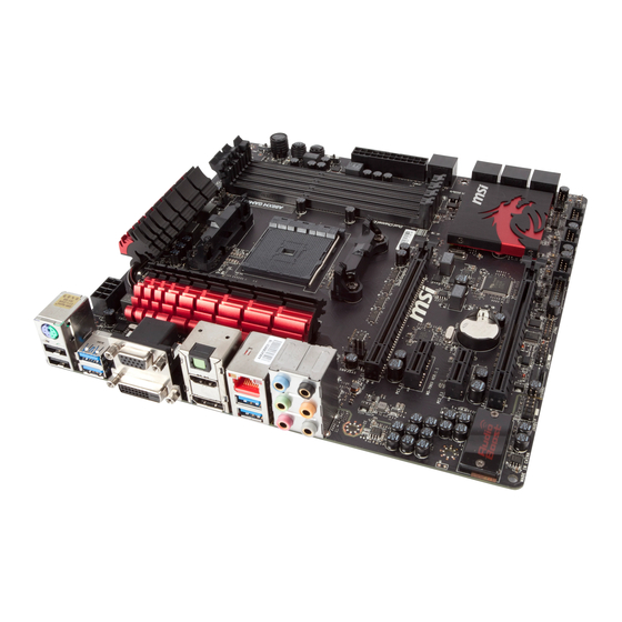
Page 169: Motherboard/ Carte Mère/ Материнские Платы
Motherboard/ Carte mère/ Материнские платы... -
Page 171: Power Connector/ Atx-Stromanshcluss/Connecteurs D'alimentation/ Pазъема Питания
Power Connector/ ATX-Stromanshcluss/ Connecteurs d'alimentation/ Pазъема питания http://youtu.be/gkDYyR_83I4 oder или... -
Page 173: Sata Hdd
SATA HDD http://youtu.be/RZsMpqxythc oder или oder или... -
Page 174: Msata Ssd
mSATA SSD A-10... -
Page 175: Front Panel Connector/ Frontpanel Anschluss/ Connecteur Panneau Avant/Pазъемов Передней Панели
Front Panel Connector/ Frontpanel Anschluss/ Connecteur panneau avant/ Pазъемов передней панели JFP1 http://youtu.be/DPELIdVNZUI JAUD1 A-11... -
Page 176: Peripheral Connector/ Peripheriestecker/Connecteur Périphérique/ Периферийных Разъемов
Peripheral Connector/ Peripheriestecker/ Connecteur périphérique/ Периферийных разъемов USB2.0 oder или USB3.0 A-12... -
Page 177: Graphics Card/ Grafikkarte/ Carte Graphique/Bидеокарты
Graphics Card/ Grafikkarte/ Carte graphique/ Bидеокарты http://youtu.be/mG0GZpr9w_A A-13... - Page 178 A-14...