
Related Manuals for National Instruments NI PXIe-8105


Summary of Contents for National Instruments NI PXIe-8105
-
Page 1: Pxi Express
PXI Express NI PXIe-8105 User Manual NI PXIe-8105 User Manual August 2006 371864C-01... - Page 2 For further support information, refer to the Technical Support and Professional Services appendix. To comment on National Instruments documentation, refer to the National Instruments Web site at ni.com/info and enter the info code feedback. © 2006 National Instruments Corporation. All rights reserved.
-
Page 3: Important Information
Warranty The NI PXIe-8105 is warranted against defects in materials and workmanship for a period of one year from the date of shipment, as evidenced by receipts or other documentation. National Instruments will, at its option, repair or replace equipment that proves to be defective during the warranty period. - Page 4 These classes are known as Class A (for use in industrial-commercial locations only) or Class B (for use in residential or commercial locations). All National Instruments (NI) products are FCC Class A products. Depending on where it is operated, this Class A product could be subject to restrictions in the FCC rules. (In Canada, the Department of Communications (DOC), of Industry Canada, regulates wireless interference in much the same way.) Digital...
-
Page 5: Table Of Contents
Introduction Benefits of PXI Express...1-1 NI PXIe-8105...1-2 Description ...1-2 Functional Overview ...1-2 NI PXIe-8105 Functional Description ...1-2 National Instruments Software ...1-4 Chapter 2 Installation and Configuration Installing the NI PXIe-8105...2-1 How to Remove the Controller from the PXI Express Chassis...2-3 BIOS Setup ...2-4... - Page 6 Boot Options... 4-2 Cables and Connections ... 4-2 Software Driver Installation ... 4-3 Upgrade Information ... 4-4 PXI Express Configuration... 4-6 Chapter 5 Troubleshooting Appendix A Specifications Appendix B Technical Support and Professional Services Glossary Index NI PXIe-8105 User Manual ni.com...
-
Page 7: About This Manual
This manual contains detailed instructions for installing and configuring the National Instruments PXIe-8105 embedded computer kit. How to Use the Documentation Set Begin by reading the NI PXIe-8105 Installation Guide, a brief quick-start guide that describes how to install and get started with your controller. This manual, the changing the installation or configuration from the defaults and using the hardware. -
Page 8: Related Documentation
• • • • • NI PXIe-8105 User Manual PICMG EXP.0 R1.0 CompactPCI Express Specification, PCI Industrial Computers Manufacturers Group IEEE Standard P1284.1-1997 (C/MM) Standard for Information Technology for Transport Independent Printer/System Interface PCI Express Base Specification, Revision 1.1, PCI Special Interest Group PXI-5 PXI Express Hardware Specification, Revision 1.0, PXI... -
Page 9: Introduction
Introduction This chapter provides overview information for PXI Express and the NI PXIe-8105 embedded controller. Benefits of PXI Express The PXI (PCI eXtensions for Instrumentation) industry standard, an open specification governed by the PXI Systems Alliance (PXISA), has quickly gained adoption and grown in prevalence in test, measurement, and control systems since its release in 1998. -
Page 10: Ni Pxie-8105
NI PXIe-8105 embedded computer. NI PXIe-8105 Functional Description The NI PXIe-8105 is a modular PC in a PXI Express 3U-size form factor. Figure 1-1 is a functional block diagram of the NI PXIe-8105. Following the diagram is a description of each logic block shown. - Page 11 Ethernet x1 PCIE Express Card/34 Slot GPIB GPIB Connector The NI PXIe-8105 consists of the following logic blocks on the CPU module and the I/O (daughter card) module. The CPU module has the following logic blocks: • • • •...
-
Page 12: National Instruments Software
Express/CompactPCI Express backplane. The Super I/O block represents the other peripherals supplied by the NI PXIe-8105. The NI PXIe-8105 has one serial port, and an ECP/EPP parallel port. The Gigabit Enet connects to either 10 Mbit, 100 Mbit, or 1,000 Mbit Ethernet interfaces. - Page 13 RTSI or PXI synchronization, self-calibration, messaging, and acquiring data to extended memory. For more information visit ni.com/daq National Instruments’ Modular Instruments use specialized drivers suited to each product’s specialization. Express VIs provide customized, interactive programming of instruments in a single interface and soft front panels provide an interface for testing the functionality of each instrument with no programming required.
- Page 14 Chapter 1 Introduction NI-VISA is the National Instruments implementation of the VISA specification. VISA is a uniform API for communicating and controlling USB, Serial, GPIB, PXI, VXI, and various other types of instruments. This API aids in the creation of portable applications and instrument drivers. For...
-
Page 15: Installation And Configuration
NI PXIe-8105 controller. Installing the NI PXIe-8105 This section contains general installation instructions for the NI PXIe-8105. Consult your PXI Express chassis user manual for specific instructions and warnings. Caution To protect both yourself and the chassis from electrical hazards, leave the chassis powered off until you finish installing the NI PXIe-8105 module. - Page 16 Figure 2-1. Removing Protective Screw Caps Make sure the injector/ejector handle is in its downward position. Align the NI PXIe-8105 with the card guides on the top and bottom of the system controller slot. Hold the handle as you slowly slide the module into the chassis until the handle catches on the injector/ejector rail.
-
Page 17: How To Remove The Controller From The Pxi Express Chassis
13. Power on the chassis. 14. Verify that the controller boots. If the controller does not boot, refer Figure 2-2 shows an NI PXIe-8105 installed in the system controller slot of a National Instruments NI PXIe-1062Q chassis. 1 NI PXIe-1062Q How to Remove the Controller from the PXI Express Chassis The NI PXIe-8105 controller is designed for easy handling. -
Page 18: Bios Setup
NI PXIe-8105 controller features. Most users do not need to use the BIOS setup program, as the NI PXIe-8105 controller ships with default settings that work well for most configurations. Changing BIOS settings may lead to incorrect controller behavior and possibly Caution an unbootable controller. -
Page 19: Main Setup Menu
However, if an IDE/ATA device is not autodetected properly, you can specify it manually by pressing <Enter> on an item. System Information—This setting displays a screen containing important system information about the NI PXIe-8105 controller. Chapter 2 Installation and Configuration... - Page 20 • • • • Note Removing the NI PXIe-8105 controller from a chassis will trigger a “Power Failure” event. When set to Turn On the controller will attempt to power on the chassis during re-insertion. • NI PXIe-8105 User Manual Reset Configuration Data—A portion of the EEPROM on the...
-
Page 21: Integrated Peripherals Submenu
Integrated Peripherals Submenu Use this submenu to apply nondefault configurations to the front panel peripherals of an NI PXIe-8105 controller. Normally, you do not need to modify these settings, as the factory default settings provide the most compatible and optimal configuration possible. -
Page 22: Pxi Setup Menu
• NI PXIe-8105 User Manual function with this option set to either Analog or DVI. The DDC communication path is only enabled when set to Analog for an analog monitor, so certain advanced features of your analog monitor may only be enabled when routing DDC to Analog. -
Page 23: Security Menu
This setting does not prevent boot sector modification by 32-bit operating system drivers that access the hard disk directly. The default is No. Chapter 2 Installation and Configuration for detailed information NI PXIe-8105 User Manual... -
Page 24: Boot Setup Menu
The Exit setup menu includes the following settings: • • • NI PXIe-8105 User Manual Operating System Not Found IDE HDD—The internal hard drive. USB KEY—A USB based flash disk drive. USB HDD—A USB based hard disk drive. -
Page 25: System Cmos
• • System CMOS The NI PXIe-8105 contains memory backed up by a battery to store BIOS configuration information. Complete the following steps to clear the CMOS contents: Caution Do not leave the jumper on pins 2–3. Doing so decreases battery life and prevents the controller from booting. -
Page 26: Drivers And Software
The directory structure under the several levels. In the reference manuals, and National Instruments software manuals, all in Adobe Acrobat format. To access any manual, change your directory to c:\images\manuals NI PXIe-8105 User Manual 2 Clear CMOS Contents Figure 2-3. -
Page 27: Pxi Express Features
PXI Express Features PXI Express Trigger Connectivity The SMB connector on the NI PXIe-8105 front panel can connect to or from any PXI backplane trigger line. A trigger allocation process is needed to prevent two resources from connecting to the same trigger line, resulting in the trigger being double-driven and possibly damaging the hardware. -
Page 28: Pxi-1 System Configuration
The PXI specification allows for many combinations of PXI chassis and system modules. To assist system integrators, the manufacturers of PXI chassis and system modules must document the capabilities of their NI PXIe-8105 User Manual Figure 2-4. Multichassis Configuration in MAX Launch MAX. -
Page 29: Upgrading Ram
PXI specification at Upgrading RAM You can change the amount of installed RAM on the NI PXIe-8105 by upgrading the SO-DIMMs. To upgrade the RAM, remove the NI PXIe-8105 from the PXI Express chassis. -
Page 30: Hard Drive Recovery
Your system hot key is <F4>. To access the hard drive-based recovery tool, press and Note hold <F4> when video first appears during the boot process. NI PXIe-8105 User Manual 2 DDR2 SO-DIMM Socket Figure 2-5. Installing a DDR2 SO-DIMM in an NI PXIe-8105 Controller ni.com/support 2-16 ni.com... -
Page 31: Installing An Os
OS. When doing so, consider the following guidelines. Installing from a USB CD/DVD-ROM The NI PXIe-8105 supports the installation of Windows XP from a USB CD/DVD-ROM. However, many other operating systems do not support installation from a USB CD/DVD-ROM. For example, Windows 2000 aborts during the install process because it does not have drivers for the USB CD/DVD-ROM device. -
Page 32: Expresscard
Slide the card out of the slot. Caution To avoid data loss and other potential issues, stop communication with your ExpressCard device before removing it from the NI PXIe-8105. In Windows, use the Safely Remove Hardware tool to safely stop the ExpressCard. NI PXIe-8105 User Manual Hold the card so the top side is facing left. -
Page 33: Front Panel Connectors
I/O Information Front Panel Connectors Table 3-1 lists various peripherals and their corresponding NI PXIe-8105 external connectors, bus interfaces, and functions. Table 3-1. NI PXIe-8105 Peripherals Overview Peripheral Video Serial Ethernet Parallel PXI trigger GPIB device ExpressCard/34 module © National Instruments Corporation... -
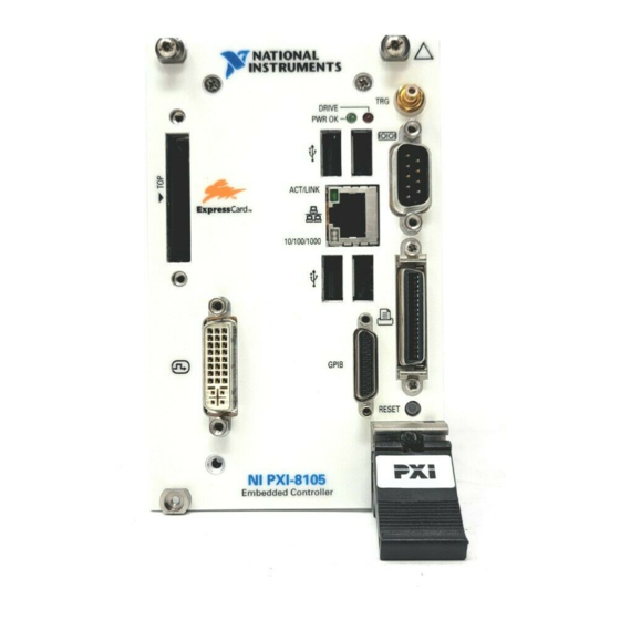
Page 34: Front Panel
Figure 3-1 shows the front panel layout and dimensions of the NI PXIe-8105. Dimensions are in inches [millimeters]. NI PXIe-8105 User Manual 3.371 [85.62] 1.546 [39.26] .000 [0] Figure 3-1. NI PXIe-8105 Front Panel Layout and Dimensions 4.393 [111.58] 3.840 [97.53] 3.551 [90.19] 3.165 [80.38] 2.490 [63.24] 2.063 [52.40]... -
Page 35: Dvi-I
DVI-I Figure 3-2 shows the location and pinouts for the DVI connector on the NI PXIe-8105. Table 3-2 lists and describes the DVI connector signals. © National Instruments Corporation Figure 3-2. DVI Connector Location and Pinout Table 3-2. DVI-I Connector Signals TMDS Data2–... - Page 36 Chapter 3 I/O Information NI PXIe-8105 User Manual Table 3-2. DVI-I Connector Signals (Continued) TMDS Data1/3 Shield Reserved Reserved +5 V Power Ground (for +5 V) Hot Plug Detect TMDS Data0– TMDSData0+ TMDS Data0/5 Shield Reserved Reserved TMDS Clock Shield TMDS Clock + TMDS Clock –...
-
Page 37: Com1
COM1 Figure 3-3 shows the location and pinouts for the COM1 connector on the NI PXIe-8105. Table 3-3 lists and describes the COM1 connector signal. AMP manufactures a serial port mating connector, part number 745491-5. © National Instruments Corporation Figure 3-3. COM1 Connector Location and Pinout Table 3-3. -
Page 38: Ethernet
Note Ethernet Figure 3-4 shows the location and pinouts for the Ethernet connector on the NI PXIe-8105. Table 3-4 lists and describes the Ethernet connector signals. AMP manufactures a mating connector, part number 554739-1. NI PXIe-8105 User Manual Figure 3-4. Ethernet Connector Location and Pinout Table 3-4. - Page 39 The controller is communicating with another computer on the LAN. 10 Mbit/sec data rate is selected. 100 Mbit/sec data rate is selected. 1000 Mbit/sec data rate is selected. Chapter 3 I/O Information Gigabit Ethernet RX_D+ RX_D– Condition NI PXIe-8105 User Manual...
-
Page 40: Parallel Port
I/O Information Parallel Port Figure 3-5 shows the location and pinouts for the IEEE 1284 (parallel) connector on the NI PXIe-8105. Table 3-6 lists and describes the IEEE 1284 connector signals. Parallel port adapter cables are available from National Instruments, part number 777169-01. - Page 41 Signal Description Data Bit 1 Data Bit 2 Data Bit 3 Data Bit 4 Data Bit 5 Data Bit 6 Data Bit 7 Initialize Printer Strobe Select Input Auto Line Feed +5 V Ground Not Connected NI PXIe-8105 User Manual...
-
Page 42: Universal Serial Bus
Universal Serial Bus Figure 3-6 shows the location and pinouts for the Universal Serial Bus (USB) connector on the NI PXIe-8105. Each controller has 4 USB ports on the front panel. Table 3-7 lists and describes the USB connector signals. -
Page 43: Trigger
The TRG connector is the software-controlled trigger connection for routing PXI triggers to or from the backplane trigger bus. Figure 3-7 shows the TRG connector location on the NI PXIe-8105. Table 3-8 lists and describes the trigger connector signals. 2 (Shield) ©... -
Page 44: Gpib (Ieee 488.2)
Chapter 3 I/O Information GPIB (IEEE 488.2) Figure 3-8 shows the location and pinouts for the GPIB connector on the NI PXIe-8105. Table 3-9 lists and describes the GPIB connector signals. ITT Canon manufactures a GPIB mating connector, part number MDSM-25SC-Z11-V51. - Page 45 DIO8# REN# 18–25 3-13 Chapter 3 I/O Information Signal Description Not Data Accepted Interface Clear Service Request Attention Chassis ground Data Bit 5 Data Bit 6 Data Bit 7 Data Bit 8 Remote Enable Logic Ground NI PXIe-8105 User Manual...
-
Page 46: Expresscard/34 Slot
Chapter 3 I/O Information ExpressCard/34 Slot The NI PXIe-8105 controller is equipped with an ExpressCard/34 slot on the front panel, which provides I/O expansion and options for removable storage. Figure 3-9 shows the location and pinouts for the ExpressCard/34 slot on the NI PXIe-8105. - Page 47 PE Wake Power PE Reset Power Power Clock Request PE Presence Reference Clock – Reference Clock + Ground PE Data Receive – PE Data Receive + Ground PE Data Transmit – PE Data Transmit + Ground NI PXIe-8105 User Manual...
-
Page 48: Front Panel Features
The NI PXIe-8105 has the following front-panel features: • • Data Storage The NI PXIe-8105 has the following data storage features: • • NI PXIe-8105 User Manual A system reset pushbutton (press the button to generate a reset to the... -
Page 49: Common Configuration Questions
This chapter answers common configuration questions you may have when using a NI PXIe-8105 embedded controller. General Questions What do the LEDs on the NI PXIe-8105 front panel mean? Refer to the LED status descriptions in the Chapter 3, After shutting down my NI PXIe-8105 controller, the Ethernet LEDs continue to blink. -
Page 50: Boot Options
There are some limitations when booting from a USB device. Windows XP can be installed from a USB CD/DVD-ROM, but earlier versions of Windows cannot. The NI PXIe-8105 BIOS configures the USB devices so that they will work in a DOS environment. -
Page 51: Software Driver Installation
How do I connect a standard 25-pin LPT cable to the NI PXIe-8105? The NI PXIe-8105 uses a type C LPT connector. Most parallel port devices use a type A connector. To use a device with a standard type A LPT connector, you need to use a type C-to-type A LPT adapter. -
Page 52: Upgrade Information
Chapter 4 Common Configuration Questions How do I install software from a CD? The compact size of the NI PXIe-8105 does not allow for an integrated USB CD/DVD-ROM drive. If you are using Windows XP, you have the following options: •... - Page 53 . For peripheral drivers, refer to KnowledgeBase 3H3COSD8 downloads/ ni.com My NI PXIe-8105 does not have an internal floppy drive. Is there a way to use an external drive? Yes. The NI PXIe-8105 controller supports and can boot from USB floppy drives.
-
Page 54: Pxi Express Configuration
For details, refer to the Installation and Why doesn’t the NI PXIe-8105 work with the PXI-8220 or PXI-8221? The serialized IRQ line is not routed to the chipset on the PXIe-8105. This prevents PC cards using ISA interrupts from working with the PXIe-8105. -
Page 55: Troubleshooting
This chapter answers common troubleshooting questions you may have when using the NI PXIe-8105 embedded computer. What if the NI PXIe-8105 does not boot? Several problems can cause a controller not to boot. Here are some things to look for and possible solutions. - Page 56 If the system has been booted without a monitor attached, the NI PXIe-8105 may have defaulted to the CRT connector being disabled. Press <Ctrl-Alt-F1> to re-enable the CRT in Windows. For additional information, refer to KnowledgeBase 3OHCFRD8 at My system boots fine as long as a particular module is not in my chassis.
- Page 57 Move the jumper on W2 from pins 1–2 to pins 2–3 as shown in Figure 5-1. Wait one second. Move the jumper back to pins 1–2. Reinstall the controller in the chassis. 2 Clear CMOS Contents Figure 5-1. Clearing the CMOS Contents Chapter 5 Troubleshooting 3 Pin 1 NI PXIe-8105 User Manual...
-
Page 58: Specifications
Specifications This appendix lists the electrical, mechanical, and environmental specifications of the NI PXIe-8105 embedded computer. Features On-die L2 cache Dual-Channel DDR2 RAM Hard Drive Ethernet PXI Express 4 Link Configuration PXI Express 2 Link Configuration GPIB (IEEE 488 Controller) - Page 59 Maximum altitude...2,000 m (800 mbar) Pollution Degree ...2 Indoor use only. Clean the NI PXIe-8105 with a soft nonmetallic brush. Make sure that the device Caution is completely dry and free from contaminants before returning it to service. NI PXIe-8105 User Manual...
-
Page 60: Operating Environment
MIL-PRF-28800F Class 2 high temperature limit.) (Tested in accordance with IEC-60068-2-56.) accordance with IEC-60068-2-1 and IEC-60068-2-2. Meets MIL-PRF-28800F Class 3 low temperature limit.) accordance with IEC-60068-2-1 and IEC-60068-2-2. Meets MIL-PRF-28800F Class 3 limits.) (Tested in accordance with IEC-60068-2-56.) NI PXIe-8105 User Manual... -
Page 61: Shock And Vibration
• • For EMC compliance, operate this device according to printed documentation. Note NI PXIe-8105 User Manual Operating ...5 to 500 Hz, 0.3 g Nonoperating ...5 to 500 Hz, 2.4 g EN 61010-1, IEC 61010-1 UL 61010-1, CAN/CSA-C22.2 No. 61010-1 , search by model number or product line, and click the EN 61326 EMC requirements;... - Page 62 Waste Electrical and Electronic Equipment (WEEE) EU Customers At the end of their life cycle, all products must be sent to a WEEE recycling center. For more information about WEEE recycling centers and National Instruments WEEE initiatives, visit © National Instruments Corporation 73/23/EEC;...
- Page 63 Technical Support and Professional Services Visit the following sections of the National Instruments Web site at ni.com • • • • © National Instruments Corporation for technical support and professional services: Support—Online technical support resources at include the following: –...
- Page 64 You also can visit the Worldwide Offices section of office Web sites, which provide up-to-date contact information, support phone numbers, email addresses, and current events. NI PXIe-8105 User Manual and could not find the answers you need, contact ni.com ni.com/niglobal to access the branch ni.com...
- Page 65 Basic Input/Output System—BIOS functions are the fundamental level of any PC or compatible computer. BIOS functions embody the basic operations needed for successful use of the computer’s hardware resources. © National Instruments Corporation Value –9 – 6 –3 tera NI PXIe-8105 User Manual...
- Page 66 LCD computer displays and digital projectors. It was developed by an industry consortium, the Digital Display Working Group (DDWG). Extended Capabilities Parallel. EEPROM Electronically Erasable Programmable Read Only Memory. Electromagnetic Compatibility. Electromagnetic interference. NI PXIe-8105 User Manual ni.com...
- Page 67 LabWindows/CVI or LabVIEW. interrupt A means for a device to request service from another device. interrupt level The relative priority at which a device can interrupt. © National Instruments Corporation Glossary NI PXIe-8105 User Manual...
- Page 68 Mean time between failure. NI-488 or NI-488.2 The National Instruments software for GPIB systems. NI-DAQ The National Instruments software for data acquisition instruments. NI-VISA The National Instruments implementation of the VISA standard—An interface-independent software that provides a unified programming interface for VXI, GPIB, and serial instruments.
- Page 69 SO-DIMM Small Outline Dual In-line Memory Module. SPI Bus Serial Peripheral Interface—A standard for controlling most any digital electronics that accept a clocked serial stream of bits. © National Instruments Corporation Glossary NI PXIe-8105 User Manual...
- Page 70 Glossary Universal Serial Bus. Volts. Video Graphics Array—The minimum video display standard for all PCs. Watts. NI PXIe-8105 User Manual ni.com...
- Page 71 ExpressCard connector and signals, 3-14 GPIB connector and signals, 3-12 parallel port connector and signals, 3-8 peripheral expansion overview (table), 3-1 trigger connector and signals, 3-11 Universal Serial Bus (USB) connector and signals, 3-10 conventions used in the manual, vii NI PXIe-8105 User Manual...
- Page 72 3-1 Ethernet, 3-1 ExpressCard, 3-1, 3-14 GPIB, 3-1, 3-12 parallel port, 3-1, 3-8 PXI trigger, 3-1 serial, 3-1, 3-5 trigger, 3-11 USB, 3-1, 3-10 video, 3-3 dimensions, 3-2 features, 3-16 LEDs, 4-1 functional overview of NI PXIe-8105, 1-2 ni.com...
- Page 73 2-12 installation See also configuration configuration in MAX (figure), 2-14 injector/ejector handle position (caution), 2-2 NI PXIe-8105 installed in a PXI Express chassis (figure), 2-3 procedure, 2-1 removing NI PXIe-8105 from PXI Express chassis, 2-3 removing protective screw caps...
- Page 74 1-4 specifications, A-1 troubleshooting, 5-1 upgrading RAM, 2-15, 4-4 NI support and services, B-1 NI-DAQmx, 1-5 NI-VISA, 1-6 NI PXIe-8105 User Manual operating environment specifications, A-2, OS directory, 2-12 OS installation from USB CD/DVD-ROM, 2-17 overview, 2-17 parallel port...
- Page 75 Serial ATA controller, using SCSI hard drive in addition, 4-1 Serial ATA Hard Disk, 1-4 serial port, 3-1 setting up the NI PXIe-8105 BIOS, 2-4 shock and vibration specifications, A-4 socket 479 1 CPU, 1-3 SO-DIMM logic block, 1-3 software...
- Page 76 Index Waste Electrical and Electronic Equipment (WEEE) specifications, A-5 Web resources, B-1 NI PXIe-8105 User Manual Y-splitter cable figure, 4-3 using mouse and keyboard without, 4-3 using with PS/2 mouse and keyboard, 2-3 ni.com...