
Related Manuals for Daikin BRC1E51A7


Summary of Contents for Daikin BRC1E51A7
- Page 1 WIRED REMOTE CONTROLLER INSTALLATION MANUAL MODEL BRC1E51A7 Be sure to read this installation manual before conducting the installation of this product.
-
Page 3: Table Of Contents
Contents 1. Safety Precautions ......2 2. Accessories ........4 3. Remote controller installation procedure .......... 4 4. Functions and menu items of remote controller buttons ..10 5. Power-on .......... 12 6. Field setting method ....... 13 7. Test operation method (in the case of SkyAir) .... -
Page 4: Safety Precautions
Safety Precautions Also see installation manual attached to the indoor unit. Please read these “Safety Precautions” carefully before installing air conditioning equipment and be sure to install it correctly. ● The precautions described herein are classifi ed as WARNING and CAUTION. They both contain important information regarding safety. - Page 5 CAUTION To avoid leakage and electric shock due to entry of water or insects, fi ll the wiring through hole with putty. To avoid electric shocks, do not operate with wet hands. Do not wash the remote controller with water, as this may result in electric shocks or fi re. Install the indoor and outdoor units, power cord and connecting wires at least 1 meter away from televisions or radios to prevent picture interference and noise.
-
Page 6: Accessories
Accessories The following accessories are included. Quick Wood screw Small screw Clamp Manual CD Wiring retainer Reference (φ3.5×16) (M4×16) (2 pcs.) (2 pcs.) (1 pc.) (1 pc.) (1 pc.) (1 pc.) Remote controller installation procedure Determine where to install the remote controller. 1. - Page 7 Determine the direction of controller wiring outlet (back outlet, left outlet, upper center outlet, upper outlet). 3-4-1 Back outlet 3-4-2 Left outlet Cut off resin area (hatched area). Cut off thin area (hatched area) with nippers or the like, and then remove burr with a fi le or the like.
- Page 8 Sheath part in the remote controller case should be stripped. Ca. 10mm For easy wiring, it is better to keep ca. 10mm difference Peel the shield and sheath between the length of two wires. Cutting guideline of the wiring Sheath stripping length: ●...
- Page 9 3-5-2 Left outlet Indoor unit P1P2 Lower case Upper case PC-board 3-5-3 Upper outlet Wiring retainer Wiring retainer Upper case Install attached Wiring wiring retainer to prevent wiring pinch according to left figure. Cross-section Indoor unit P1P2 Lower case Upper case PC-board 3-5-4 Upper center outlet...
- Page 10 CAUTION ● Perform wiring apart from a power line not to receive electrical noise (external noise) during the wiring. ● Seal wiring draw-in port securely with putty (fi eld supply) to prevent entry of insects or the like. Fixing procedure of lower case. In the case of wiring center upward drawing or rearward drawing, see wiring procedure fi...
- Page 11 Switch box for one unit (with no cover) Switch box (field supply) (Use optional accessory KJB111A) (Installation pitch) Small screws (M4×16) CAUTION ● Select fl at place for installation face as possible. ● And, do not tighten the installation screws too much not to deform the lower case. Install the upper case as original condition.
-
Page 12: Functions And Menu Items Of Remote Controller Buttons
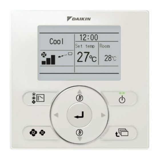
Functions and menu items of remote controller buttons Functions and menu items (1) Operation mode selector button (11) LCD (with backlight) (4) Up button (5) Down button (6) Right button (7) Left button (9) Operation lamp (8) On/Off button (3) Menu/Enter button (10) Cancel button (2) Fan speed control button Operation mode selector button... - Page 13 Left button Field setting menu ● Used to highlight the next items on the left-hand side. Test operation ON/OFF ● Display contents are changed to Register Service Contract previous screen per page. Field setting list Group No. setting On/Off button Indoor unit Airnet No.
-
Page 14: Power-On
Power-on ● Check for completion of indoor/outdoor units wiring. ● Check for closing of EL. COMPO. BOX cover of indoor and outdoor units before power-on. Followings are displayed after <Main remote controller> <Sub remote controller> power-on. Off reminder Timer Off reminder Timer “Connection under check Connection under check Connection under check... -
Page 15: Field Setting Method
Field setting method Press and hold Cancel button for <Basic screen> 4 seconds or longer. Field setting menu is displayed. Set temperature Select Field setting list in the °C fi eld setting menu, and press Return Press the menu button Menu/Enter button. - Page 16 Press Menu/Enter button. Setting confi rmation screen is displayed. <Setting confi rmation screen> Select and press Menu/ Field setting list Enter button. Setting details are Is it settled by setting? determined and fi eld setting list screen returns. Return Setting In the case of multiple setting changes, repeat “...
- Page 17 Mode FIRST SECOND CODE NO. Note) 2 CODE Description of setting Note) 1 ON/OFF input from outside (setting ON/OFF for when forced ON/OFF is to be Forced OFF ———— ———— operation operated from outside). 12 (22) Thermostat differential changeover (setting for when using remote 1°C 0.5°C ————...
-
Page 18: Test Operation Method (In The Case Of Skyair)
Test operation method (in the case of SkyAir) ∗ In the case of VRV, see the manual attached to the outdoor unit. Also see installation manuals attached to the indoor unit and the outdoor unit. ● Check that wiring work of the indoor unit and the outdoor unit is completed. ●... - Page 19 Press On/Off button within about 10 seconds. The test operation starts. Cool Set temperature Check operation condition for Press On/Off button °C 3 minutes. (within 10 seconds). ∗ Note) In the case of above-men- Test Operation tioned procedures in reverse order, test Press Menu/Enter button.
- Page 20 CAUTION ● If operation is not available due to any malfunction, refer to following Failure diagnosis method . ● After the test operation fi nishes, check that error code record is not displayed in the Service Contact/Model Information screen of the main menu according to the following procedure. 7-14 Press Menu/Enter button in the basic <Basic screen>...
-
Page 21: Checking Procedure Of Error Record
Remote controller display Description ● Power outage, power voltage error or open-phase ● Wrong wiring (between indoor and outdoor units) ● Indoor PC-board assembly failure No display ● Remote controller wiring disconnection ● Remote controller failure ● Fuse blow (outdoor unit) Display of ●... -
Page 22: Registration Method Of The Service Contract
Registration method of the service contract ● Registration of the service contract. Press and hold Cancel button for <Basic screen> 4 seconds or longer in the basic screen. Field setting menu is displayed. <Field setting menu screen> Field setting Select Register Service Contract Test operation ON/OFF the fi... -
Page 23: Confi Rmation Of Registered Details
Confi rmation of registered details 10-1 Press Menu/Enter button in the basic <Basic screen> screen. Main menu is displayed. Cool Select Service Contact/Model Info Set temperature the main menu, and press Menu/Enter °C button. Press Menu/Enter button. Return Setting 10-2 Press Cancel button twice. -
Page 24: Clock Setting
Clock Setting 11-1 Press Menu/Enter button in the basic <Basic screen> screen. Main menu is displayed. Select Clock setting in the main <Main menu screen> menu, press Menu/Enter button. MainMenu Convenient functions 11-2 Select “year”, “month”, “day” and “time” Setting status list Clock setting by using (Left/Right) button and... - Page 26 EM08A086 (0903) HT...