Table of Contents
Advertisement
Quick Links
Download this manual
See also:
Maintenance Manual
Advertisement
Chapters
Table of Contents

Related Manuals for Printronix p4280


Summary of Contents for Printronix p4280
- Page 1 Setup Guide P4280 Printer (IPDS)
-
Page 3: Setup Guide
P4280 Printer (IPDS) Setup Guide P/N 151347–001, Rev C... - Page 4 Printronix, Inc. makes no representations or warranties of any kind regarding this material, including, but not limited to, implied warranties of merchantability and fitness for a particular purpose. Printronix, Inc. shall not...
-
Page 5: Table Of Contents
1–3 The P4280 IPDS Printer ......... - Page 6 Connect the Power Cord ......... 2–11 Install the Operating System Diskette .
- Page 7 Mono/Dual Case Selection (Coax only) ......3–18 Line Spacing Selection (Coax only) ......3–18 LCD Language Selection .
- Page 8 Image Test ..........3–36 Recycle Test .
-
Page 9: Introduction
1–3 The P4280 IPDS Printer .......... -
Page 10: About This Setup Guide
This Setup Guide is designed so you can quickly find the information you need to install and configure your P4280 IPDS printer. Related Documents For more information about your printer, refer to the P4280 IPDS Operator’s Guide. It Includes step–by–step instructions on daily printer operations. How to Locate Information •... -
Page 11: Warnings And Special Information
Warnings and Special Information For your safety and to protect valuable equipment, it is very important that you read and comply with all information highlighted under special headings: WARNING Conditions that could harm you as well as damage the equipment. CAUTION Conditions that could damage the printer or related equipment. -
Page 12: The P4280 Ipds Printer
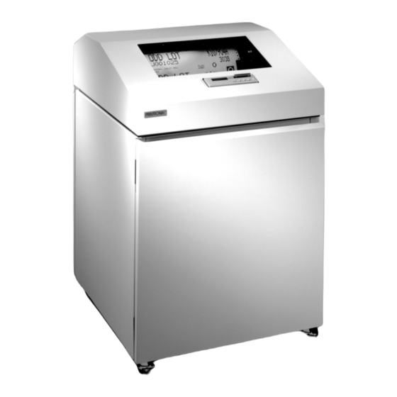
The P4280 IPDS Printer Figure 1–1. The P4280 IPDS Printer The P4280 IPDS printer has the latest refinements in line matrix printing technology, yet is very easy to use. The liquid crystal display and status lamps on the control panel communicate with you directly and clearly. You can select many functions on your printer at the control panel or by sending commands from the host computer. -
Page 13: Features
Features IPDS Intelligent Printer Data Stream (IPDS), the P4280 standard emulation, allows you to print sophisticated graphics with its system–to–printer data stream. • Systems Application Architecture (SAA) compatibility. • Merged applications. Each type of data has its own source data and is merged when sent to the printer. -
Page 14: Built-In Diagnostic Tools
Emulations The P4280 IPDS supports coax and twinax interfaces. With a coax interface, the P4280 IPDS emulates an IBM 4234, Model 007/011 and can also be used in place of 3262 and 3268 printers. With a twinax interface, the printer emulates the IBM 4234, Model 008/012. -
Page 15: Compatible System Attachments
Compatible System Attachments You can attach the printer to the following computers and display systems: Coax Emulation Twinax Emulation 4321/31/61 display printer adapters System/36 (SSP 5.1 plus IPDS PRPQ P84094) ES/9370 work station controller System/38 (with Rel. 8 System/38 Control Program Facility) AS/400 processor 3174, 3274 control units 5394/5494 control units... -
Page 16: Local And Remote Attachments
Local and Remote Attachments You can attach the P4280 IPDS either locally or remotely. A local attachment is a direct line. A remote attachment is a telecommunications line, such as a modem. (See Figure 1–3.) NOTE: Coax direct connections require a 3x74 cluster controller. -
Page 17: Changing Printer Settings
Changing Printer Settings Changing printer settings, such as forms length, is called configuring. You can configure the printer with the control panel or with commands in the host data stream. NOTE: Set by Host/Job override operator set. Many people will use the control panel to change a setting. The control panel is designed for easy use. -
Page 18: Ipds: An Overview
IPDS: An Overview Processing a Page Your printer can print page by page (AFP) or it can behave as a line printer (typically non–AFP). This section describes how the printer prints page by page. (Appendix B explains the two printing methods in more detail.) Your IPDS–capable printer builds a page by gathering all the page descriptor commands and data blocks that are specified in the data stream. -
Page 19: The Command Sets
The Command Sets IPDS consists of the following command sets, which are defined in more detail in your 4234/IPDSR Emulation Printers Programmer’s Reference Manual. Text This set contains the commands used to present text information on a page, on a page segment, or on an overlay. -
Page 20: The Data Towers
The Data Towers Most of the IPDS commands contain data fields. The type of data is categorized into the following data towers: Text The Presentation Text Object Content Architecture (PTOCA) commands are a part of of the text data tower. This information is necessary to print text in a page, a page segment, or an overlay. -
Page 21: The States
The States IPDS–capable printers are known as “state machines.” As the printer recognizes a specific command, it moves to the state identified with that command. Home State The initial operating state. The printer returns to this state after a page, an overlay, a page segment, or a downloaded font has been sent. - Page 22 • IBM 3270 Information Display System: Configurator (p/n GA27–2076) • IBM 3270 Information Display System: 3274 Control Unit Description and Programmer’s Guide (p/n GA23–0061) • IBM 3270 Information Display System Component Description (p/n GA27–2749) • Presenting the IBM System/36 (p/n SC21–9016) •...
-
Page 23: Setting Up The Printer
Setting Up the Printer Chapter Contents Before You Begin ..........2–3 Select a Power Source . - Page 24 As a Local IPDS–capable Printer ....... . 2–26 As a Remote IPDS–capable Printer .
-
Page 25: Before You Begin
Before You Begin... Read this chapter carefully before installing and operating the printer. The P4280 IPDS printer is easy to install, but for your safety and to protect valuable equipment, perform all the procedures in this chapter in the order presented. -
Page 26: Select A Site
Select a Site Printer Cover Cabinet Rear Door 146.1 cm (57.5 in.) 102.5 cm (40.3 in.) 57.2 cm (22.5 in.) 73.7 cm (29 in.) 191.5 cm (75.4 in.) 68.6 cm 68.6 cm (27 in.) (27.0 in.) Figure 2–1. Printer Dimensions Select a printer site that: •... -
Page 27: Remove The Shipping Restraints
Remove the Shipping Restraints Tie wraps and foam pads protect the platen and tractors from damage during shipment. They must be removed in order for the printer to operate. WARNING To prevent possible injury, do not connect the AC power source before removing the shipping restraints. - Page 28 Outer Foam Pad (Left) Tie Wrap Upper Paper Guide Tie Wrap Outer Foam Pad (Right) Figure 2–2. Tie Wraps and Outer Foam Pads Remove the Tie Wraps and Outer Foam Pads 1. Raise the printer cover. 2. Cut and remove the tie wraps securing the paper fence. (See Figure 2–2.) 3.
- Page 29 Platen Protective Foam Tractor Support Shaft Tractor Gate Tractor Lock Forms Thickness Tractor Gate Lever Figure 2–3. Platen Protective Foam Remove the Platen Protective Foam 1. Open the tractor gates. Push the tractor locks down. Move the tractors outward as far as they will go. (See Figure 2–3.) 2.
- Page 30 Hammer Bank Protective Foam Figure 2–4. Hammer Bank Protective Foam Remove the Hammer Bank Protective Foam 1. Rotate the hammer bank protective foam toward the front of the printer and remove it from between the ribbon mask and hammer bank. (See Figure 2–4.) 2–8 Setting Up the Printer...
- Page 31 Protective Film Figure 2–5. Protective Film Remove the Protective Film 1. Carefully peel the protective film off the control panel. (See Figure 2–5.) Setting Up the Printer 2–9...
-
Page 32: Release The Paper Chains
Release the Paper Chains Tie Wrap Tie Wrap Plastic Bags Figure 2–6. Releasing the Paper Chains 1. Open the rear cabinet door. 2. Cut the tie wraps and release the paper chains from the bags at the rear of the printer frame. Remove the tie wraps and bags. (See Figure 2–6.) 3. -
Page 33: Connect The Power Cord
Connect the Power Cord Power Switch AC Power Connector Figure 2–7. Connecting the Power Cord 1. Verify that the voltage source at the printer site conforms to the requirements specified on page 2–3. 2. Make sure the printer power switch is set to O (off). 3. -
Page 34: Install The Operating System Diskette
Install the Operating System Diskette Diskette Drive Figure 2–8. The Diskette Drive NOTE: There are separate diskettes for coax and twinax emulations. Make sure the power is turned off. Open the rear cabinet door. Locate the diskette drive. Remove the operating system diskette from its shipping container. Make sure the diskette is not write–protected. -
Page 35: Turn The Printer On
Turn the Printer On Power Switch Figure 2–9. The Power Switch Set the power switch to the ON position. The printer displays the following messages: “DIAGNOSTIC TEST PASSED” “LOADING DIRECTORY” “STATION ADDRESS X” (where X=currently set station address) “LOADING FONTFILE X” (where X=several font files) “ON LINE”... -
Page 36: Set The Station Address
Set the Station Address If you have a twinax interface, use the following steps to set the station address in order to avoid address conflicts with other devices which may be on the same cable. If you have a coax interface, skip this section and continue with “Connect the Interface Cable.”... - Page 37 Step Press Result Notes Press PREV or NEXT STATION ADDRESS 001 until the desired address (0–6) displays. Refer to your list of addresses. You CANNOT use these addresses since they are already being used. If two devices have the same address, neither device is usable. TEST/ENTR Selects the new address.
-
Page 38: Save The Station Address
Save the Station Address This section explains how to save your address in one of four configurations (Config. A – D). The configurations are stored on the operating system diskette––they will not be lost if you turn off the printer. Later, when you turn on the printer, the last used configuration will be loaded. - Page 39 Step Press Result Notes PRT 1 The locked state pre- ENTER SWITCH LOCKED vents the configuration settings from being NEXT changed. START ON LINE STOP Close the printer cover. Go to the next section. Setting Up the Printer 2–17...
-
Page 40: Connect The Interface Cable
“T” and connect the cable to the host computer. 2. If you are installing a coax cable, insert it into the coax connector on the printer and connect it to the host computer. The P4280 IPDS Printer can be attached to the following: Coax Emulation Twinax Emulation 4321/31/61 display printer System/36 (SSP 5.1 plus IPDS... -
Page 41: Load The Paper
Load the Paper Upper Paper Guide Tractor Gate Forms Thick- ness Lever Figure 2–11. Opening the Tractor Gates This section explains how to load paper for the first time. 1. Turn on the printer. 2. Press START/STOP. The LCD should show “OFF–LINE.” 3. - Page 42 EDGE PAPER Paper Slot Figure 2–12. Aligning and Feeding the Paper 7. Open the front door of the cabinet. Align the paper supply with the label on the floor. 8. Feed the paper up through the paper slot inside the cabinet. Hold the paper to prevent it from slipping down through the paper slot.
- Page 43 Tractor Paper Ribbon Path Diagram Figure 2–13. The Right Tractor 10. Pull the paper above and behind the ribbon mask, a silver–colored metal strip. (Refer to the ribbon path diagram on the shuttle cover.) Press both tractor locks down. Load the paper on the tractor sprockets and close the tractor gates.
- Page 44 Horizontal Tractor Lock Adjustment Knob Paper Scale Figure 2–15. Aligning the Paper 12. Align the paper according to the paper scale on the shuttle cover. To do this, turn the horizontal adjustment knob until the left tractor is aligned with the number “1” on the paper scale. (You can also use the paper scale to count columns.) CAUTION To avoid damage to the printer, do not position the left tractor to the left...
- Page 45 Paper Guide Assembly Figure 2–16. Checking the Paper Feed 14. Press FORM FEED four times to ensure that the paper feeds properly beyond the tractors and into the paper guide assembly. 15. Lower the upper paper guide. 16. Continue with the next section. Setting Up the Printer 2–23...
-
Page 46: Set The Top-Of-Form
Set the Top–of–Form TOF Indicator Paper Perforation Vertical Position Knob Figure 2–17. Setting Top of Form The top–of–form setting determines where the first line of print appears on a page. Setting the top of form allows you to make sure that the placement of the characters and margins is correct before you run a print job. -
Page 47: Install The Ribbon
Install the Ribbon Ribbon Mask Hub Latch Ribbon Guide Figure 2–18. Installing the Ribbon 1. Make sure the forms thickness lever is raised as far as it will go. Remove the ribbon spool from the package. 2. With the ribbon to the outside, place the right spool on the right hub. Press down on the spool until the hub latch snaps in place. -
Page 48: Set Up The Host Computer
Set Up the Host Computer This manual does not explain how to access the host computer configuration menus. For additional setup information, refer to your IBM documentation. Configure the Printer on AS/400 Systems As a Local IPDS–capable Printer At the host computer, enter the command CRTDEVPRT and set the following parameters with the values listed below. -
Page 49: As A Remote Ipds-Capable Printer
As a Remote IPDS–capable Printer A remote IPDS–capable printer can be configured only to a 5394 or 5494 remote control unit. The auto configuration, CRTDEVPRT and CFGLCL commands can be used to set the following parameters with the values listed below. Italicized values are ones that you must set according to your system setup. -
Page 50: Configure The Printer On Systems 36/38
Configure the Printer on Systems 36/38 System/36 (5360, 5362, 5363) • You must have SSP 5.1 or later • For a system 36 host, select printer type as PH (IPDS printers). • To utilize IPDS on a System/36 host, you need the appropriate PRPQs from IBM (these allow printing bar codes, etc.). -
Page 51: Test The Printer
Test the Printer Step Press Result Notes Make sure the printer top cover is raised, the ribbon is installed, and the printer is on and loaded with full–width paper. Press: START OFF LINE STOP PRINTER TEST UNTIL PRINTER TEST IMAGE TEST PRINTER TEST RECYCLE TEST TEST/ENTR... - Page 52 Step Press Result Notes START ON LINE STOP Close the printer top cover. NOTE: After running printer self–tests, it is recommended to power the printer off then back on before starting a job. 2–30 Setting Up the Printer...
-
Page 53: Configuring The Printer
Configuring the Printer Chapter Contents Overview ............3–4 Entering the Configuration Menus . - Page 54 Orientation Selection (Coax only) ....... . 3–21 Carriage Return at MPP+1 (Coax only) .
- Page 55 All H’s Test ..........3–36 Underline Test .
-
Page 56: Overview
Overview Configuration is setting the printer operating characteristics to match those of the print job sent from the host computer. You can configure the printer with the control panel or with data stream codes sent in the data stream from the host computer. This chapter shows you how use the control panel. - Page 57 Off–Line No Line Sync Diagnostics Load Config. Save Config. Printer Configuration Menu From Disk On Disk Test Menu Page 3–30 Page 3–32 Page 3–28 Page 3–34 Configuration Printout For Twinax Configuration Image Test Hex Dump Menu see page 3–8 and for Recycle Test Error Log Menu Coax Configuration see...
-
Page 58: Entering The Configuration Menus
Entering the Configuration Menus Press the following sequence of switches to unlock the TEST/ENTR switch and enter the configuration menus. Step Press Result Notes Open the printer cover. Press: START OFF LINE STOP ENTER SWITCH PREV NOT LOCKED You MUST press PREV. CONFIGURATION MENU Exiting the Menus without Saving... -
Page 59: The Configuration Menus
The Configuration Menus This section shows the configuration menus and all of their submenus for the twinax and coax emulations. After the overview of the Configuration Menus, an example is provided showing how to use the control panel switches to navigate among the Configuration Menu submenus and options. - Page 60 Twinax Configuration Menu Char. Density Line Density Signal Volume Switch Volume Print Quality Selection Selection Selection Selection Selection 10 cpi* 6 lpi* Draft 8 lpi Max. Print Pos. Max. Page Length LCD Language Charset/Codepage ..Selection Selection Selection Selection CONTINUED English* 037 English/U.S./Can* German...
- Page 61 Font Size Station Address ..Default Setting Graphics and Bar Selection Selection Selection Code Quality Factory* By Host* High graphics / High bar code* Compressed Host control 001* Standard Low graphics / Low bar code High graphics / Low bar code Low graphics / High bar code Paperout Graphics Scaling...
- Page 62 Coax Configuration Menu Char. Density Line Density Signal Volume Switch Volume Print Quality Selection Selection Selection Selection Selection 10 cpi* 6 lpi* 8 lpi Draft LCD Language Max. Print Pos. Max. Page Length Mono/Dual Case Line Spacing Selection Selection Selection Selection Selection Upper and lower case*...
- Page 63 Graphics and Bar Screen Size Orientation Carr. Return ..at MPP+1 Code Quality Selection Selection Left to right* High graphics / High bar code* 960 bytes Right to left Host control 1920 bytes* Low graphics / Low bar code 2560 bytes High graphics / Low bar code 3440 bytes Low graphics / High bar code...
-
Page 64: Changing Settings
Changing Settings Configuration Menu Signal Volume Switch Volume Print Quality Selection Selection Selection Draft To change settings, refer to the following pages. Changing the print quality to NLQ is provided as an example. NOTE: You can press CAN/BPRT or the up arrow key at any time to cancel your changes and return to off line. - Page 65 Step Press Result Notes Open the printer cover. Press: START OFF LINE STOP The unlocked state ENTER SWITCH NOT LOCKED allows you to make configuration changes. PREV You MUST press PREV. CONFIGURATION MENU PRINT QUALITY UNTIL SELECTION PRINT QUALITY IS XXX Press PREV or NEXT PRINT QUALITY IS NLQ...
- Page 66 Step Press Result Notes CONFIGURATION MENU UNTIL Go to page 3–29, step 5. SAVE CONFIG ON DISK If you do not save, the current configuration will be lost when you turn off the printer. Follow the next steps to exit the menu. OFF LINE UNTIL PRT 1...
-
Page 67: Configuration Settings
Configuration Settings Signal Volume Selection The alarm volume informs you of a printer error condition. Values: On (factory default) Switch Volume Selection You can set the switch volume so that it beeps when you make a configuration selection. Values: On (factory default) Print Quality Selection The printer is capable of printing in different grades of quality, depending on your requirements. -
Page 68: Character Density Selection
Character Density Selection Also known as Characters Per Inch (cpi). This is the number of characters that print per horizontal inch. A command sent via the host data stream can override this setting. If the new cpi value conflicts with the MPP, the MPP setting changes to the default (132). -
Page 69: Maximum Print Position Selection
Maximum Print Position Selection Also known as MPP or line length. A computer program may set the MPP for some print jobs. The one you choose with the control panel may be different. The default is 132 MPP at 10 cpi. NOTE: Change the cpi setting before you change the MPP. -
Page 70: Mono/Dual Case Selection (Coax Only)
Mono/Dual Case Selection (Coax only) Characters can be printed either all uppercase or upper– and lowercase. If you are printing Japanese–English or Japanese–Katakana, the printer can print only in dual case (upper and lowercase). Values: Upper and lowercase (factory default) Uppercase only Line Spacing Selection (Coax only) Lines can be either single or double spaced. -
Page 71: Character Set/Code Page Selection
Character Set/Code Page Selection This configuration function lets you select the character set and code page. Code page tables are shown in the 7234 Printer Models 011 and 012 Product and Programming Description (GC31–3879–0). A code page is a group of characters that are specific for a country, a language, or a symbols set. -
Page 72: Default Setting Selection
Default Setting Selection This is the configuration which displays when the printer is powered up. The default setting is Factory for both coax and twinax. Values: Factory (factory default) Font Size Selection You can choose the following fonts for printing text. The default is the host computer, which selects the font. -
Page 73: Orientation Selection (Coax Only)
Screen Size Selection (Coax only) This configuration is used for setting the buffer size. Values: 960 bytes 1920 bytes (factory default) 2560 bytes 3440 bytes 3564 bytes NOTE: The buffer size can be set larger then needed. Orientation Selection (Coax only) This configuration function is used to set the direction in which the lines will be printed. -
Page 74: New Line At Mpp+1 (Coax Only)
New Line at MPP+1 (Coax only) This configuration function enables/disables an automatic New Line (NL) when the carriage return occurs at Maximum Print Position +1 (MPP+1). MPP is also known as line length. Values: On (factory default) Formfeed Active (Coax only) Moves the logical print head to the left margin of the first line on the next page. -
Page 75: Null Suppression (Coax Only)
Null Suppression (Coax only) This configuration function enables/disables the printing of null characters as spaces. When turned on, an entire line of null character does not produce a line feed. When turned off (factory default), the null character is treated as a space. -
Page 76: Automatic Formfeed (Coax Only)
Automatic Formfeed (Coax only) This configuration function enables/disables an automatic form feed at the end of a print job. Values: Off (factory default) Timeout Suppression (Coax only) On a fault, suppresses operator intervention required being sent to the host for printer faults. Values: Off (factory default) Extended Attribute Buffer (Coax only) -
Page 77: Early Print Complete
Early Print Complete When Early Print Complete is off (the default), the printer waits until printing finishes before issuing a “Print Complete” status, resulting in slower processing of the next print job. (The spool file is not released until printing is completed) When Early Print Complete is on, the printer does not wait until finishing a job before issuing a “Print Complete”... -
Page 78: Pmd Selection
PMD Selection PMD, or Paper Motion Detection, may be enabled or disabled. If PMD is enabled and a paper jam occurs, an audible alarm sounds (if the alarm is also enabled), ‘‘PAPER JAM” appears on the message display, and the printer stops printing. -
Page 79: Test Width Selection
Test Width Selection This option determines the width of the paper for self–test printouts. Values: 80 columns (factory default) 132 columns Phasing Setting This is used to test the vertical alignment. Ask your authorized service representative to do this test. Values: 0 to 252 Horizontal Resolution Selection... -
Page 80: Saving Your New Configuration
Saving Your New Configuration Save Config. On Disk Defaults You can save up to four different configurations to meet four unique print job requirements. For example: Config. A: Selects Draft print quality,10 cpi, 6 lpi, etc. Config. B: Selects NLQ print quality, 12 cpi, 8 lpi, etc. The configurations are stored on the operating system diskette—they will not be lost if you turn off the printer. - Page 81 Step Press Result Notes SAVE CONFIG X ON DISK Press PREV or NEXT SAVE CONFIG B ON DISK until the desired value (A–D) displays. TEST/ENTR Displays briefly. CONFIGURATION SAVING ... The configuration is SAVE CONFIG saved. ON DISK Print your configuration (page 3–30, step 4.) If you do not print, follow the next steps. OFF LINE UNTIL PRT 1...
-
Page 82: Printing The Current Configuration
Printing The Current Configuration Diagnostics Menu Configuration Printout Hex Dump Menu Error Log Menu Directory Printout The configuration printout lists the configuration parameters currently stored and in use. The printout lists the main menus and sub–menu parameters in the same order as they occur when you use the control panel to configure the printer. - Page 83 Step Press Result Notes You MUST press PREV. DIAGNOSTICS UNTIL MENU (Another parameter may DIRECTORY PRINTOUT display.) CONFIGURATION UNTIL PRINTOUT TEST/ENTR Displays briefly. CONFIGURATION PRINTING ... CONFIGURATION PRINTOUT OFF LINE UNTIL PRT 1 The locked state pre- ENTER SWITCH LOCKED vents the configuration settings from being NEXT...
-
Page 84: Loading A Configuration
Loading a Configuration Load Config. from Disk Factory You can store up to four configurations to meet four unique print job requirements. You can load any of these stored configurations (A–D) at any time. Modifying a Saved Configuration You can change a saved configuration by “writing” over it. For example, you already saved and used Configuration B for past print jobs, but now you want to modify Configuration B by changing only one parameter. - Page 85 Step Press Result Notes LOAD CONFIG X FROM DISK Press PREV or NEXT LOAD CONFIG B FROM DISK until the desired value (A–D) displays. TEST/ENTR Displays briefly. CONFIGURATION LOADING... The configuration is LOAD CONFIG loaded. FROM DISK If you are modifying your configuration, go to page 3–12. Change all of the necessary values.
-
Page 86: Printer Tests
Printer Tests Printer Test Image Test Recycle Test All E Test All E & TOF Test All H Test Underline Test Black Test Paperout Test Shuttle Slow Test Shuttle Fast Test Phasing Test Burn–In Test To initiate the printer tests, go to page 3–35. IMPORTANT With the exception of the shuttle speed test, if you press UP, NEXT, or PREV while a test is printing, the test will stop and paper will feed to the... - Page 87 Step Press Result Notes Open the printer cover. Press: START OFF LINE STOP You MUST press PREV. PRINTER TEST UNTIL <name of test> See previous page for all <name of test> of the tests. TEST/ENTR Some tests show <name of test> PRINTING...
-
Page 88: Image Test
Image Test Produces a grid. Used to identify skewing and shading. Recycle Test Prints a “sliding” pattern of the current character set. Used to identify missing or malformed characters, improper vertical alignment, or vertical compression. All E’s Test A pattern of all uppercase letter E’s used to identify missing characters, misplaced dots, smeared characters, improper phasing, or light/dark character variations. -
Page 89: Paper Out Test
Paper Out Test A comb pattern prints down the page to the edge of the perforation. A successful test will print the comb pattern to the very edge of the perforation. If there is any distance between the edge of the last printed row and the perforation, the paper out distance needs to be adjusted. - Page 90 3–38 Configuring the Printer...
-
Page 91: Diagnostics And Fault Messages
Diagnostics and Fault Messages Chapter Contents Diagnostic Tests ..........4–2 Tests and the Control Panel . -
Page 92: Diagnostic Tests
You do not need to send data from the host computer to test printer operation. The P4280 IPDS has built–in diagnostic tests you can use to check the print quality and operation of your printer. The built–in diagnostic tests are listed below. -
Page 93: Tests And The Control Panel
Shuttle Slow Test Verifies proper operation by exercising shuttle and ribbon motion at low speed. Shuttle Fast Test Verifies proper operation by exercising shuttle and ribbon motion at fast speed. Phasing Test A timing parameter used by service personnel to adjust vertical alignment of dots in character printing. - Page 94 Step Press Result Notes Open the printer cover. Press: START OFF LINE STOP PRINTER TEST UNTIL <name of test> See previous pages for <name of test> all of the tests. TEST/ENTR Some tests show <name of test> PRINTING... “RUNNING.” To stop TEST/ENTR <name of test>...
-
Page 95: Printing The Hex Code
Printing the Hex Code A hex code printout (or hex dump) translates all incoming data to hexadecimal equivalents. A hex dump lists all EBCDIC character data received from the host computer with their corresponding two–digit hexadecimal codes. Hex dumps are used to troubleshoot data stream related problems. - Page 96 Step Press Result Notes When “OFF LINE” dis- HEX DUMP PRINT OFF LINE plays, the printer cannot receive data from the host. Press PREV or NEXT to HEX DUMP –>RS232 OFF LINE scroll through the op- tions (Print or RS232). START When “ON LINE”...
-
Page 97: Fault Messages
Fault Messages If the printer’s fault sensors detect a problem, the control panel status lamps flash on and off and the display shows an error message. If a fatal error occurs, “PRINTER HALTED” displays below the error message. Fault messages are summarized in Table 4–1. There are two kinds of displayed faults: •... - Page 98 Table 4–1. Fault Messages Message Operator Displayed Correctable? Explanation Solution 48V POWER FAIL Internal error. Call your authorized service rep- PRINTER HALTED resentative. CCB TO MECH ERR. Internal error. Call your authorized service rep- PRINTER HALTED resentative. DISK READ ERROR No disk in drive.
- Page 99 Table 4–1. Fault Messages (cont) Message Operator Displayed Correctable? Explanation Solution SHUTTLE FAN ERR. Internal error. Call your authorized service rep- PRINTER HALTED resentative. SHUTTLE STALL No shuttle movement Make sure the ribbon is not or the shuttle is moving twisted and the forms thickness at the wrong speed.
-
Page 100: The Error Log
The Error Log The error log lists all of the errors that occurred since the last time the log was cleared. For each error that has occurred, the error log lists a two–digit code, the error message, and the number of occurrences of the error. Under the Diagnostics menu you can access the Error Log option to print or clear the error log. - Page 101 Step Press Result Notes To print the error log, follow the next step. To clear the error log, go to step 11. TEST/ENTR The printer outputs the PRINT ERROR error log. If the log is empty, only the header prints. Go to step 13.
- Page 102 4–12 Diagnostics and Fault Messages...
-
Page 103: A Printer Specifications
Printer Specifications Contents Ribbon Specifications ..........A–2 Paper Specifications . -
Page 104: Ribbon Specifications
Ribbon Specifications NOTE: Use only the ribbons listed below. Each kit contains six ribbons. Black Text Ribbon P/N 9107234–01 Bar Code/OCR Ribbon P/N 9107234–02 Paper Specifications NOTE: The following are general paper specifications. Test paper stocks with your applications before ordering large quantities. Paper Type Edge–perforated, fanfold, 3 to 16 inches wide... -
Page 105: Printer Dimensions
Labels On Backing One–part continuous perforated fanfold back form. Labels must be placed at least 1/6 inch from the fanfold perforation. Backing adhesive must not be squeezed out during printing. Sheet Size 3– to 16–inches (7.62 to 40.64 cm) wide, including the two standard perforated tractor feed strips. -
Page 106: Environmental Characteristics
Environmental Characteristics Temperature ° ° Operating to 40 ° ° Storage – 40 to 70 Relative Humidity Operating 10% to 90% (noncondensing) Storage 5% to 95% (noncondensing) Acoustic Noise Levels 52 dBA (tested per ISO 7779) A–4 Printer Specifications... -
Page 107: Electrical Characteristics
Electrical Characteristics Input Power Voltage 100 to 120 VAC or 200 to 240 VAC Phase Single Frequency 50 or 60 Hz Max RMS Current 6A @ 100V; 3A @ 200V Power Rating Standby 160 Watts Operating 400 Watts Radio Frequency Interference (RFI) Radio Frequency Interference Tested/Certified to RFI Standards FCC 15 Class A;... - Page 108 A–6 Printer Specifications...
-
Page 109: Line Matrix Printing
Line Matrix Printing Chapter Contents Overview ............B–2 Two Methods for Printing a Job . - Page 110 Overview Your printer creates characters and graphics by a printing technique called line matrix printing. Line matrix printing consists of printing patterns of ink dots on paper, an entire line at a time. Each text character is stored in memory as a pattern of dots on a logical grid called the dot matrix.
- Page 111 Direction of shuttle movement Paper Advances Start Paper Feed Character Line Paper Space Advances 1 Hammer 1 Hammer Print Span Print Span Used for lowercase descender only Used for underline and lowercase descender Figure B–1. Line Matrix Printing Line Matrix Printing B–3...
-
Page 112: Printing Speed
Two Methods for Printing a Job Your IPDS–capable printer can print page by page (AFP), or it can behave as a line printer (non–AFP). You specify the printing method at the host. Printing page by page is also known as deferred printing. The printer gathers all of the page descriptor commands and data blocks to create the page and then prints the page (when the End Page command is received). - Page 113 Table B–1. Print Speeds Print Mode Text Printer Speed Draft Uppercase only Uppercase only Uppercase only 180 – 460 * Upper & Lowercase Upper & Lowercase 156 – 216 * * In NLQ mode, character shape also affects print speed. Line Matrix Printing B–5...
- Page 114 Line Matrix Printing B–6...
- Page 115 Glossary active column The horizontal location on the paper where the next character will print. active line The vertical location on the paper where the next character will print. active position The position on the paper where the next character will print. The intersection of the active column and the active line.
- Page 116 command sequence Two or more bytes that instruct the printer to perform a special function. compressed Refers to a typeface with a font height smaller than normal. Character width is not changed. Abbrev. for characters per inch. A measurement of monospaced fonts indicating the horizontal character density.
- Page 117 font, monospaced Also called fixed–pitch fonts. Every character, regardless of horizontal size, occupies the same amount of font pattern space. All monospaced fonts use specific pitch size settings. Monospaced fonts are sometimes used when strict character alignment is desired (tables, charts, spreadsheets, etc.). font, proportional A font in which the width of a character cell varies with the width of the character.
- Page 118 logical link The parameters that specify data transfer, control, or communication operations. Maximum Page Length. Also known as forms length. The number of lines that can be printed on a page. Maximum Print Position. Also known as line length. The number of characters printed on a line.
- Page 119 point A unit of length in printing and typography, used to specify type sizes, heights of font characters, etc. There are 72 points in a vertical inch; thus, one point equals 1/72 inch, or approximately 0.0138 inch. Some examples of point sizes are: This is 8 point type.
- Page 120 roman A type style in which the characters are upright. This is sentence is printed in a roman type style. Systems Application Architecture. Will eventually link all IBM computers and printers, allowing IPDS to be accepted across various platforms. SNA Character String. Usually commands to set printer format, etc.
- Page 121 Index Numbers Carriage Return at MPP+1 parameter, (coax 48V POWER FAIL PRINTER HALTED only), 3–21 message, 4–8 CCB TO MECH ERR. PRINTER HALTD message, 4–8 Chains, paper, 2–10 Changing a saved configuration, 3–32 Accessing configuration menus, 3–6 Changing configuration settings, 3–12 Changing printing parameters, 1–9 Address, printer, setting, 2–14 Character density parameter, 3–16...
- Page 122 System 36/38, 2–28 Formfeed active parameter, (coax only), 3–22 Connecting interface cable, 2–18 Forms, setting top–of–form, 2–24 Forms length, 3–17 Connecting power cord, 2–11 CPI Parameter, 3–16 Glossary, Glossary–1 Graphics and bar code quality parameter, Data towers, 1–12 3–20 Default setting parameter, 3–20 Graphics command set, 1–11 Deferred printing, B–4 Graphics scaling parameter, 3–25...
- Page 123 IO Image command set, 1–11 IPDS, 1–5, 1–10 New line at MPP+1 parameter, (coax only), command sets, 1–11 3–22 compatibility, 1–6 Null suppression parameter, (coax only), data towers, 1–12 3–23 page processing, 1–10 states, 1–13 OFF LINE LINE CHECK PAR. message, 4–8 ON LINE LINE CHECK PAR.
- Page 124 Power cord, attaching, 2–11 Print format parameters, feature description, Saved configuration, changing, 3–32 1–5 Saving configuration, 3–28 Print quality parameter, 3–15 Saving station address, 2–16 Print quality parameter, graphics and bar Screen size parameter, (coax only), 3–21 code, 3–20 Self–test printouts, paper width, 3–27 Printer Dimensions, A–3 Setting printer address, 2–14...
- Page 125 Test width parameter, 3–27 Testing after installation, 2–29 Testing vertical alignment, 3–27 Tests, diagnostic, 3–34, 4–2 Text command set, 1–11 Timeout suppression parameter, (coax only), 3–24 Top–of–form, 2–24 Turning printer on, 2–13 Twinax configuration menu, 3–8 Twinax interface, 1–6 Twinax interface, setting printer address, 2–14 Underline test, 3–36 Unpacking a new printer, 2–5...
- Page 126 Index–6...
- Page 128 RINTRONIX 17500 C ARTWRIGHT 19559 92713-9559 RVINE, 714/863-1900 HONE: 714/660-8682 RINTRONIX EDERLAND OX 163, IEUWEWEG 283 NL-6600 A IJCHEN ETHERLANDS (31) 8894-90111 HONE: (31) 246-419768 RINTRONIX 512 C 02-15 ANE, EDOK NDUSTRIAL STATE 1646 INGAPORE (65) 449-7555 HONE: (65) 449-7553 151347–001C...