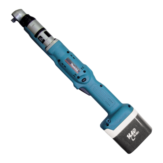
Makita BFL300F Technical Information
Cordless angle screwdriver 14.4v
Hide thumbs
Also See for BFL300F:
- Instruction manual (65 pages) ,
- Instruction manual (17 pages) ,
- Instruction manual (29 pages)
Advertisement
Quick Links
Download this manual
See also:
Instruction Manual
T
ECHNICAL INFORMATION
Models No.
Description
C
ONCEPT AND MAIN APPLICATIONS
Models BFL300F and BFL400F have been developed
as specialist tools for industrial assembly applications,
featuring high torque capacity of 30N.m (BFL300F)/
40N.m (BFL400F).
Their brief advantages are;
*High precision fastening
*DC brushless motor for increased no load speed
*14.4V, 2.7Ah Ni-MH battery equipped with new type
battery cells for more efficient energy supply to motor
Model BFL401F is a sister tool designed for Italy.
These models do not include battery and charger.
S
pecification
Model No.
Voltage: V
Capacity: Ah
Cell
Capacity
Fastening torque: N.m
No load speed: min.-
Net weight: kg (lbs)
*Note: 12.7mm (1/2") with optional Spindle G complete
S
tandard equipment
No (however, with Protector for some countries, and with Torque adjust tool for some countries)
O
ptional accessories
Ni-MH battery BH1427
Chargers DC24SA, DC14SA, DC14SC
Automatic refreshing adapter ADP03
Switch lever set (paddle switch)
Spindle G complete (12.7mm square drive)
Protectors Red, Blue, Yellow, Clear
Torque adjust tool
BFL300F, BFL400F, BFL401F
Cordless Angle Screwdriver 14.4V
BFL300F
Hard joint
Soft joint
=rpm
1
Model No.
Length (L)
Width (W)
Height (H)
Head height (HH)
Center height (CH)
BFL400F/ BFL401F
14.4
2.7
Ni-MH
9.5mm (3/8") Square drive*
16 - 30
16 - 30
400
2.3 (5.1)
L
HH
CH
*Battery is optional.
Dimensions: mm (")
BFL300F
BFL400F/ BFL401F
506 (20)
510 (20-1/16)
73 (2-7/8)
104 (4-1/8)
104 (4-1/8)
31.5 (1-1/4)
34 (1-5/16)
16 (5/8)
25 - 40
25 - 40
260
2.4 (5.3)
NEW TOOL
P 1 / 13
H
W
73 (2-7/8)
18 (11/16)
Advertisement

Related Manuals for Makita BFL300F


Summary of Contents for Makita BFL300F
- Page 1 Models No. BFL300F, BFL400F, BFL401F Description Cordless Angle Screwdriver 14.4V ONCEPT AND MAIN APPLICATIONS Models BFL300F and BFL400F have been developed as specialist tools for industrial assembly applications, featuring high torque capacity of 30N.m (BFL300F)/ 40N.m (BFL400F). Their brief advantages are;...
-
Page 2: Table Of Contents
[2] LUBRICATION AND ADHESIVE See the parts breakdown below. Apply 2.0g of Makita Grease N. No.2 to the portions designated with the mark of Apply Makita seal lubricant to the portions designated with the mark of Apply Loc-Tite 603 to the portions designated with the mark of Fig. -
Page 3: Disassembling/ Assembling
P 3 / 13 [3] DISASSEMBLING/ ASSEMBLING [3] -1. Disassembling/ Assembling of Job Light Section DISASSEMBLING *Shown in Fig. 2 are the parts of Job light section. 1) Remove Lead cover (on which Ring spring 36 is installed) and Ring spring 29 using a slotted screwdriver. (Figs. 3, 4) 2) Remove Light covers (R) and (L) while pushing the portion designated with the gray circle to unlock the tab on Light cover (R) from the slot in (L). -
Page 4: Disassembling/ Assembling Of Bearing Retainer
Fig. 10. ASSEMBLING 1) After applying Makita seal lubricant No.101 to O ring 15, put O ring 15 and Bearing retainer in place on Spindle complete. 2) Put 2g of Makita seal lubricant No.101 in the gear room of Angle head complete. -
Page 5: Disassembling/ Assembling Of Clutch Case Section
5) Assemble Spur gear 14 and Pin 3 (5 pcs each) to Carrier, and then Thin washer 14 and Retaining ring S-14 to complete Carrier section. 6) Insert Carrier section into Angle head complete, and apply 1.5g of Makita seal lubricant No.101 to Spur gear 14. 7) Install Flat washer 26 and Retaining ring R-32. -
Page 6: Disassembling/ Assembling Of Clutch Section
Then install Retaining ring R-26. Remark: Remember to place Compression spring 5 between Clutch case and Clutch assembly. 3) Put an appropriate amount of Makita seal lubricant in the hole on Spur gear 21. (Fig. 1) [3] -5. Disassembling/ Assembling of Clutch Section Note: When repairing Clutch section, it is recommended to entirely replace Clutch assembly with fresh one. - Page 7 Remove from Gear case section. ASSEMBLING 1) After applying Makita grease N No.2 to teeth of all Spur gears, shafts of Carrier complete and shafts of Spur gear 20 complete, assemble Ball bearing 6805LLB and Carrier complete (A) to Gear case. (Fig. 1) And then assemble Internal gear 47 and Spur gears from the opposite side.
-
Page 8: Disassembling/ Assembling Of Switch Section
P 8 / 13 [3] -6. Disassembling/ Assembling of Gear Case Section (cont.) Fig. 24 Fix lead wires with lead wire holders. Plate Lens Fix lead wires with lead wire holders. Terminal Fig. 25 Color of Lead Wires Blue, Black Yellow, White Yellow, Blue Purple, Yellow... - Page 9 P 9 / 13 [3] -7. Disassembling/ Assembling of Switch Section (cont.) Fig. 28 ASSEMBLING Put Leaf spring in place on F/R Change lever, and Compression protrusion on F/R Change lever spring 4 on Switch lever (A). Put F/R Change lever, Switch lever and Switch unit for rotation reverse in place.
- Page 10 P 10/ 13 ircuit diagram Fig. 28 Motor control unit Main switch Terminal Stator Switch unit B Switch unit A (for rotation (for Trigger) reverse) Controller LED PWB Buzzer (for display) circuit Switch unit C (for clutch) circuit (for job Color index of lead wires' sheath light) Black...
- Page 11 P 11/ 13 iring diagram [1] Wiring Around Controller Fig. 29 rib (A) Route the lead wires (orange, white, blue) from Controller to Stator between the two pins. Route the lead wires from Switch unit (for rotation reverse) between rib (A) and rib (C).
- Page 12 P 12/ 13 iring diagram [2] Wiring Around Stator Fig. 30 Switch unit (for Clutch) Connector (to LED circuit) Place Connectors and the sag of lead wires in the space between rib (E) and the inside wall of Housing. inside wall of Housing Connector Route the following lead wires from Controller rib (E)
- Page 13 P 13/ 13 iring diagram [3] Wiring the Lead Wires from LED Circuit on Lead Holder Fig. 31 LED circuit Make the lead wires so that they cannot be pulled to disconnect LED circuit from Controller when Switch cover is installed. Hook the lead wires Route the lead wires between on the five tabs of...