Hitachi DH 40FR Technical Data And Service Manual
Hide thumbs
Also See for DH 40FR:
- Instruction manual and safety instructions (56 pages) ,
- Handling instructions manual (61 pages)

Related Manuals for Hitachi DH 40FR


Summary of Contents for Hitachi DH 40FR
- Page 1 MODEL DH 40FR Hitachi Power Tools TECHNICAL DATA ROTARY HAMMER DH 40FR SERVICE MANUAL LIST No. E472 Jul. 2003 SPECIFICATIONS AND PARTS ARE SUBJECT TO CHANGE FOR IMPROVEMENT...
- Page 2 REMARK: Throughout this TECHNICAL DATA AND SERVICE MANUAL, symbols are used in the place of company names and model names of our competitors. The symbols utilized here are as follows: Competitors Symbols Utilized Model Name Company Name 11248EVS BOSCH...
-
Page 3: Table Of Contents
7-2. Caution Plate ............................9 8. REFERENCE INFORMATION ....................... 10 8-1. Grease Replacement ........................10 8-2. O-Ring Replacement ........................10 8-3. Structure of the Model DH 40FR Rotary Hammer ................10 9. REPAIR GUIDE ..........................14 9-1. Disassembly ...........................14 9-2. Reassembly ............................17 9-3. Screw Locking Agent TB1401 ......................20 9-4. -
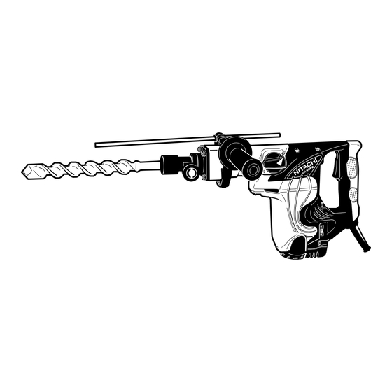
Page 4: Product Name
Hitachi Rotary Hammer, Model DH 40FR 2. MARKETING OBJECTIVE The Model DH 40FR is an upgraded version of the current Model DH 40FA/DH 40FB, which features the use of spline shank tools. The performance, durability and operability are greatly improved. With this competitive Model DH 40FR, we aim to enhance the share of spline shank type rotary hammers. -
Page 5: Selling Point Descriptions
4-1-6. Needle-pin type slip clutch The Model DH 40FR is equipped with a needle-pin type slip clutch for higher slip torque accuracy and enhanced safety (same as the Model DH 40FA/DH 40FB). -
Page 6: Specifications
5. SPECIFICATIONS 5-1. Specifications Drill bit (Max. diameter): 40 mm (1-9/16") Capacity Core bit (Max. diameter): 105 mm (4-1/8") Power source AC single phase 50 Hz or 60 Hz Voltage 120 V 230 V Current 9.2 A 4.8 A Power input 950 W AC single-phase series commutator motor Motor type... -
Page 7: Optional Accessories
5-2. Optional Accessories 1. Drilling work for through-holes (rotation + hammering) (1) Drill bit (hexagon shank) Outer diameter (mm) Overall length (mm) Code No. 25 (1") 985375 400 (15-3/4") 38 (1-1/2") 985376 2. Drilling work for anchor holes (rotation + hammering) (1) Drill bit (taper shank) (2) Taper shank adapter (3) Cotter... - Page 8 (3) Core bit Outer diameter (in.) Code No. Outer diameter (in.) Code No. 25 mm (1") 955994 54 mm (2-1/8") 955155 29 mm (1-1/8") 955995 64 mm (2-1/2") 956002 32 mm (1-1/4") 955996 79 mm (3-1/8") 955157 35 mm (1-3/8") 955998 94 mm (3-11/16")
- Page 9 7. Digging work (substitute pick-ax) (hammering) (1) Scoop Overall length Width Code No. 405 mm (16") 105 mm (4-1/8") 985386 8. Syringe (for chip removal) Code No. 318085 Code No. 320859 9. Grease for hammer, hammer drill 70 g (2.5 oz) Tube 500 g (1.1 lbs.) Can 30 g (1 oz) Tube Code No.
-
Page 10: Comparisons With Similar Products
6. COMPARISONS WITH SIMILAR PRODUCTS 6-1. Specification Comparisons Maker Model • HITACHI HITACHI HITACHI DH 40FR DH 40FA/FB DH 38YE Item Capacity Drill bit dia. (mm) (1-9/16") (1-9/16") (1-1/2") (1-9/16") Core bit dia. (mm) (4-1/8") (4-1/8") (3-15/16") (4-1/8") Power input... -
Page 11: Drilling Speed Comparisons
Drilling speed varies considerably depending on the work conditions. Use the factory test results shown in Fig. 1 for comparison purpose only. Drilling speed (mm/min.) Drill bit Maker Model dia. (mm) HITACHI DH 40FR HITACHI DH 40FA/FB HITACHI DH 38YE HITACHI DH 40FR HITACHI DH 40FA/FB... -
Page 12: Chiseling Performance Comparison
7. PRECAUTIONS IN SALES PROMOTION In the interest of promoting the safest and most efficient use of the Model DH 40FR Rotary Hammer by all of our customers, it is very important that at the time of sale the salesperson carefully ensures that the buyer seriously recognizes the importance of the contents of the Handling Instructions, and fully understands the meaning of the precautions listed on the Caution Plate attached to each tool. -
Page 13: Reference Information
8-1. Grease Replacement The striking portion and the speed reduction portion of the Model DH 40FR respectively use different types of grease. It is not necessary to replenish the grease unless the tool is disassembled for repair or there is grease leakage due to a damaged seal. - Page 14 Torque transmission Armature revolution is transmitted to the second gear to rotate the bevel gear via the slip mechanism between the second gear and bevel pinion axes. Rotation of the bevel gear is then transmitted to the cylinder keyed thereto through the clutch. Cylinder rotation is transmitted through the spline connection to the second hammer.
- Page 15 Slip clutch mechanism The slip clutch mechanism is described below with reference to Fig. 5. The bevel pinion and the gear holder are coupled together by the key and press-fitting. Spring (C) and needle pins are housed in elongated grooves of the gear holder. The needle pin is pressed against the inner face of second gear by spring (C) to allow idle rotation of the second gear relative to the gear holder.
- Page 16 Sealing and dust-proof structure The cylinder crank case section is tightly sealed with three o-rings, two oil seals and rubber seal as shown in Fig. 7. This prevents leakage of grease from the cases, while also protecting them against dust from outside. For additional dust-proof protections, a standard accessory dust cover is provided which serves to prevent dust and chips from entering the spline hole of the second hammer and causing imperfect fitting of the drill bit.
-
Page 17: Repair Guide
9. REPAIR GUIDE The numbers in [Bold] correspond to the item numbers in the Parts List and exploded assembly diagrams. 9-1. Disassembly (1) Disassembly of the tool holder Disassembly procedures are illustrated in Fig. 8. Pull Knob (A) [3] outward in the direction indicated by the arrow, and turn it slightly so that its end surface comes to rest on the flange portion of the Front Cover [5]. - Page 18 Clutch Spring [19] Clutch [22] Cylinder Washer [18] Second Hammer [10] Striker [20] Cylinder [17] Bevel Gear [26] Connecting Rod [25] Piston [23] Damper [12] Damper Washer [11] Cylinder Crank Case [40] Bevel Pinion [41] Crank Shaft [34] Fig. 9 (4) Disassembly of the first gear and the crank shaft Remove grease from the Connecting Rod [25] side and Cylinder...
- Page 19 (4) Disassembly of the cylinder As illustrated in Fig. 12, insert the drill bit secured with a vise into the Second Hammer [10] and Cylinder [17]. Put the wrench (J-123 No. 970885) to the width across flats of the Cylinder Cap [13] and turn it to loosen the Cylinder Cap [13] (right-hand thread).
-
Page 20: Reassembly
9-2. Reassembly Reassembly can be accomplished by following the disassembly procedure in reverse. However, special attention should be given to the following items. (1) Reassembly of the first gear and the crank shaft Press-fit Oil Seal (B) [39] into the Cylinder Crank Case [40] and mount O-ring (S-40) [38]. Press-fit the Ball Bearing 6203DDCMPS2L [37]. - Page 21 Gear [50]. Insert the ten Needles [49] being careful not to incline them, then push in ten Springs (C) [48] as shown in Fig. 17. Fill the slots and the through holes of the Gear Holder [47] with Hitachi Motor Grease No.
- Page 22 Motor Grease No. 29 to the Needle Bearing (M661) [56] and the pinion portion of the Armature Ass'y [75]. Fill 30 g of Hitachi Motor Grease No. 29 in the Cylinder Crank Case [40] on the First Gear [55] side and the Gear Cover [57] side.
-
Page 23: Screw Locking Agent Tb1401
9-3. Screw Locking Agent TB1401 Apply screw locking agent TB1401 to all hex. socket head bolts M4, M5, M6 and Cylinder Cap [13]. (Note) Be sure to apply screw locking agent ThreeBond TB1401 to the threads during reassembly, as the bolts loosened with vibration may cause damage to the tool body. -
Page 24: Insulation Tests
Mounting diagram Case (B) Control circuit ass'y (include noise suppressor) Housing Lead wires of switch and cord Lead wire of stator Lead wire of noise suppressor Tail cover Fig. 20 9-6. Insulation Tests On completion of disassembly and repair, measure the insulation resistance and dielectric strength. Insulation resistance: 7 MΩ... -
Page 25: Standard Repair Time (Unit) Schedules
10. STANDARD REPAIR TIME (UNIT) SCHEDULES Variable 60 min. MODEL Fixed DH 40FR Work Flow Housing Ass'y Stator Ass'y Gear Cover Needle Bearing Switch (C) Cord Armature Ass'y Cord Armor Ball Bearing (6201DD) Tail Cover Dust Washer (B) Ball Bearing... - Page 26 Hitachi Power Tools LIST NO. E472 ELECTRIC TOOL PARTS LIST ROTARY HAMMER 2003 • • Model DH 40FR (E1)
- Page 27 PARTS DH 40FR ITEM CODE NO. DESCRIPTION REMARKS USED 983-242 STOP WASHER 981-937 STOPPER SPRING 983-241 KNOB (A) 943-364 NEEDLE ROLLER D4X20 322-159 FRONT COVER 981-942 SEAL LOCK HEX. SOCKET HD. BOLT M6X25 985-372 STOP LEVER 956-996 O-RING (1AS-60) 981-857...
- Page 28 PARTS DH 40FR ITEM CODE NO. DESCRIPTION REMARKS USED 629-VVM BALL BEARING 629VVC2PS2L 321-277 SLIP CLUTCH ASS’Y INCLUD. 35, 41, 42, 44-52 944-525 BEARING WASHER (C) 321-276 FIRST GEAR 939-299 NEEDLE BEARING (M661) 321-319 GEAR COVER 313-078 SIDE HANDLE 313-079...
- Page 29 PARTS DH 40FR ITEM CODE NO. DESCRIPTION REMARKS USED NAME PLATE 980-063 TERMINAL 930-804 TERMINAL M4.0 (10 PCS.) FOR USA, CAN 940-778 CORD ARMOR D10.7 960-266 CORD CLIP 981-987Z CORD CLIP FOR SUI 984-750 TAPPING SCREW (W/FLANGE) D4X16 500-390Z CORD (CORD ARMOR D10.7)