Ericsson MDX Series Installation Manual
(conventional mobile radio)
Hide thumbs
Also See for MDX Series:
- Installation manual (28 pages) ,
- Operator's manual (16 pages) ,
- Service manual (15 pages)
Table of Contents
Advertisement
Quick Links
Download this manual
See also:
Service Manual
Advertisement
Table of Contents

Related Manuals for Ericsson MDX Series


Summary of Contents for Ericsson MDX Series
- Page 1 LBI-39013B Installation Manual MDX™ SERIES (Conventional Mobile Radio) MOBILE RADIO...
-
Page 2: Table Of Contents
United States. This manual is published by Ericsson Inc., without any warranty. Improvements and changes to this manual necessitated by typo- graphical errors, inaccuracies of current information, or improvements to programs and/or equipment, may be made by Ericsson Inc., at any time and without notice. -
Page 3: Introduction
IBM compatible personal computer and the following items: Serial Programming Interface Module Kit and TQ3370 Programming Cable TQ3372 MDX Series Programming Software TQ3346 (Conventional Mobile Radio) UNPACKING AND CHECKING EQUIPMENT When ready for installation, carefully unpack the radio and identify each item in the shipping container as listed below. -
Page 4: Mdx Mobile Radio
Table 1 - MDX Mobile Radio Series Optional Accessories Option Description Part Number PMAN1R Roof mount antenna with TNC connector PMCC02 Universal tone cable (used with V8001, V8022, V8024, each). PMCC9M External speaker cable, 18 inches 19A149590P8 PMCD1W External speaker cable, 16 feet, requires 19A149590P10 option PMZM1K and PMCD7Z PMCD7W... -
Page 5: Planning The Installation
PLANNING THE INSTALLATION Before starting, plan the radio installation carefully so that it will be: • safe for the operator and passengers. • convenient for the operator to use. • neat. • protected from water damage. • easy to service. •... -
Page 6: Equipment Required
EQUIPMENT REQUIRED The equipment required for installing the MDX Mobile Radio is listed below: • Electric drill for drilling mounting holes. • Drills and circle cutters as follows: • No. 31 (1/8-inch) drill for No. 8 self-tapping screws. • No. 27 (9/64-inch) drill for No. 10 self-tapping screws. •... -
Page 7: Installation In Vehicles Powered By Liquefied (Lp) Gas
INSTALLATION IN VEHICLES POWERED BY LIQUEFIED (LP) GAS Radio installation in vehicles powered by liquefied petroleum gas with the LP-gas container in the trunk or other sealed-off space within the interior of the vehicle must conform to the National Fire Protection Association Standard NFPA 58 which requires that: •... -
Page 8: Installation
INSTALLATION RUNNING CABLES To assure the feasibility of the planned cable routings, it is suggested that the cables be run before mounting the radio. Be sure to leave some slack in each cable going to the radio so that the radio may be pulled out for servicing with the power applied and antenna attached. - Page 9 Push the prepared fuse connectors into each section of the fuse holders. Place the fuse into a fuse holder section until it seats within the connector. Connect the fuse holder sections to insure a tight fit and connection. Figure 3 - Power Cable...
- Page 10 Connect the orange fused lead to the positive (+) battery terminal, and black to the negative (-) battery terminal. Always locate the fuse as close to the battery as possible. Connect the red fused lead to the ignition "on" sense point (preferably an "Accessory"...
-
Page 11: Mounting The Radio
Coil any surplus cables and secure them out of the way with the retaining strap provided. Be sure to leave some slack in the cables going to the radio so that it may be pulled out for servicing with power applied. MOUNTING THE RADIO Figure 4 - Mounting Dimensions Use the supplied mounting bracket as a template to locate the positions for... -
Page 12: Microphone Hanger
Figure 5 - Mounting Bracket Installation MICROPHONE HANGER Mount the microphone hanger in a location convenient to the operator where it will not interfere with the safe operation of the vehicle or be a hazard to the vehicle passengers. The microphone hanger is designed to be mounted with the open end of the mounting button slot pointed upward. - Page 13 Figure 6 - Microphone Hanger NOTE If mounting on a surface covered with carpet, punch holes with a small punch then make a small slit in the carpet, insert a short piece of metal tubing and drill through the tubing. Use the following procedure to mount the microphone hanger: Use the hanger as a template to mark the screw locations and drill the three small pilot holes.
-
Page 14: Microphone
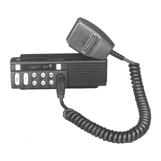
MICROPHONE The microphone connects to the MDX Mobile Radio using a plug found at the end of its attached cable. Match the pins on this plug to the pin socket on the radio and press in the plug being sure not to damage the pins. Once the plug is seated, tighten down the plug using the thumbscrew on the mic connector. -
Page 15: Option Cable Kit - Option Pmcd7Z
A permanent mount type of antenna should be located in the center of the roof or center of rear deck. Glass mounted antennas should be kept as high as possible in the top center of the rear window. Some states have laws restricting vision obstructing items from the windows. - Page 16 Figure 8 - Option Cable Pin Locations Table 2 - Option Cable Connections GROUP 14 FUNCTION GROUP 18 P1 & P2 P1 & P2 SPEAKER LO SPEAKER HI MIC HI SW A+ SERIAL REQUEST (GE STAR) CG DISABLE SW SPEAKER HI AUDIO MUTE VOLUME-SQUELCH HI MIC LO...
-
Page 17: Power Cable - Option Pmcd9A (19B801358P17)
Universal Tone Cable Option PMCC02 (19C851585P19) The Universal Tone Cable requires the Option Cable (Option PMCD7C). P1 of the Universal Tone Cable plugs into P2 of the Option Cable. The Universal Tone Cable Option provides all option connections on P2 and a 9-pin Winchester connector for connecting to external tone encoders or decoders. - Page 18 Figure 10 - Bottom View (Cover Removed) ALARM (HORN) RELAY KIT - OPTION PMSU1C (19A705499P1) Requires the use of option cable kit - option PMCC3N. The alarm relay kit option consists of the following items: (1) Relay (19A149299P1) (1) Fuse holder (1) Fuse, 1 amp, 250 volt 4 feet red wire, AWG #18 with Ring Tongue Terminal for 3/8 stud 6 feet black wire, AWG #18 with Molex #39-00-0060 terminal...
-
Page 19: External Speaker Kit - Option Pmzm1K
Crimp an insulated 1/4 inch spade tab receptacle to the other end of the black wire. Connect the receptacle to relay lug #85. Connect the horn or light circuit to lugs #30 and #87 (not 87a) using the insulated 1/4 inch spade tab receptacles. NOTE The relay contact make/break current and voltage rating is 30 amps at 16 volts. -
Page 20: Bramco Decoder Installation Notes
Pins are supplied on the ends of the external speaker cable option PMCC9M. Push these pins into sockets 2 and 9 of the connector housing supplied with the option cable. Refer to Figure 8. Plug the connector housing into P2 of the option cable. Connect the plug end of the external speaker cable to the speaker. -
Page 21: Int/Ext Speaker Kit (Pmsu5A Microphone Pa Kit (Pmpl3D)
J101 in B position J102 in A position J103 in A position Bramco DTMF Decoder option V8024 (19A149258P10) On the switch board: Cut one end of R101 (20 ohm 2W resistor) Install jumpers J101 in A position, J102 in A position, J103 in A position. INT/EXT SPEAKER KIT (PMSU5A) MICROPHONE PA KIT (PMPL3D) These two options permit the selection of an external speaker. -
Page 22: Option Interconnection Diagrams
OPTION INTERCONNECTION DIAGRAM (188D5198, Sh. 1, Rev. 1) - Page 23 OPTION INTERCONNECTION DIAGRAM (188D5198, Sh. 1, Rev. 1)
- Page 24 OPTION INTERCONNECTION DIAGRAM (188D5198 Sh. 3, Rev. 1)
- Page 25 OPTION INTERCONNECTION DIAGRAM (188D5198, Sh. 3, Rev. 1)
- Page 26 OPTION INTERCONNECTION DIAGRAM (188D5198, Sh. 6, Rev. 1)
- Page 27 This page intentionally left blank...
- Page 28 Ericsson Inc. Private Radio Systems Mountain View Road Lynchburg,Virginia 24502 Printed in U.S.A. 1-800-528-7711 (Outside USA, 804-528-7711)