Table of Contents
Advertisement
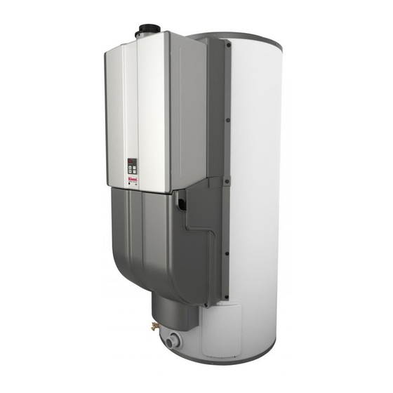
FOR INDOOR APPLICATIONS ONLY
CHS199100 ............ 119 gallon, 199,000 BTU
The Commercial Hybrid System is assembled with multiple and separately
certified components consisting of:
C199i Commercial Tankless Water Heater
Storage Tank
Controller
READ ALL OF THE INSTRUCTIONS THOROUGHLY BEFORE
INSTALLING OR OPERATING THIS SYSTEM.
(This manual is a supplement to the C199i Installation and
Operation Manual)
This manual provides information on the installation, operation, and
maintenance of the water heater. For proper operation and safety, it
is important to follow the instructions and adhere to the safety
precautions.
A licensed professional must install the water heater according to the
exact instructions in this manual.
The consumer must read the entire manual to properly operate the
water heater and to have regular maintenance performed.
WARNING
— Do not store or use gasoline or other flammable vapors and liquids in the vicinity of this or any other
appliance.
— WHAT TO DO IF YOU SMELL GAS
Do not try to light any appliance.
Do not touch any electrical switch; do not use any phone in your building.
Immediately call your gas supplier from a neighbor's phone. Follow the gas supplier's instructions.
If you cannot reach your gas supplier, call the fire department.
— Installation and service must be performed by a qualified installer, service agency or the gas supplier.
If the information in these instructions is not followed exactly, a fire or explosion
may result causing property damage, personal injury, or death.
Commercial Hybrid System
Installation and Operation Manual
Advertisement
Table of Contents

Related Manuals for Rinnai CHS199100


Summary of Contents for Rinnai CHS199100
- Page 1 Commercial Hybrid System Installation and Operation Manual FOR INDOOR APPLICATIONS ONLY CHS199100 .... 119 gallon, 199,000 BTU The Commercial Hybrid System is assembled with multiple and separately certified components consisting of: C199i Commercial Tankless Water Heater Storage Tank ...
-
Page 2: Table Of Contents
If you have any questions or feel that the manual is incomplete contact Rinnai at 1-800-621-9419 Important Safety Information Safety Definitions This is the safety alert symbol. -
Page 3: Safety Behaviors And Practices For The Consumer And Installer
Safety Behaviors and Practices for the Consumer and Installer WARNING Before operating, smell all around the appliance Use only your hand to push in or turn the gas control knob. Never use tools. If the knob will not area for gas. -
Page 4: Installation Instructions
Installing venting through a wall or roof. combustion air flow. Training in installation of Rinnai water heaters. Do not obstruct the flow of combustion and (Training can be accessed on-line at ventilation air. Combustion air shall not be www.trainingevents.rinnai.us) -
Page 5: Prepare For Installation
General Instructions (continued) Prepare for installation You must follow the installation instructions and Parts included those in Care and Maintenance for adequate Commercial Hybrid System combustion air intake and exhaust. Temperature and Pressure Relief Valve (Tank) INFORMATION ... -
Page 6: Determine Installation Location
Determine Installation Location You must ensure that clearances will be met and that the Minimum Clearances vent length will be within required limits. Consider the The minimum clearances from both combustibles installation environment, water quality, and need for and non-combustibles construction is: freeze protection. -
Page 7: Combustion Air Requirements (Common Vent Applications Only)
Combustion Air Requirements Room air can only be used in applications that utilize either the approved Rinnai common vent method, or the commercial hybrid system (Refer to Rinnai Common Vent manual for further details regarding common vented applications) This water heater requires adequate combustion air for ventilation and dilution of flue gases. Failure to provide adequate combustion air can result in unit failure, fire, explosion, serious bodily injury or death. -
Page 8: Venting Requirements
Combustion Air Requirements Exhaust Checklist for Combustion Air and Venting Requirements □ Verify proper clearances around the vents . □ Ensure that the Combustion Air Requirements are followed that will provide sufficient combustion air for the appliance. □ Ensure approved venting components have been Vent termination per ANSI Z223.1/NFPA 54. -
Page 9: Commercial Hybrid System Room Air Installation
Commercial Hybrid System Room Air Installation NOTICE Prior to the installation of the vent system, the unit must be properly adjusted for the venting configuration selected for the application. Any issues resulting from improper installation will not be covered by warranty. ... -
Page 10: Terminal Clearances
Direct Vent Terminal Clearances A vent termination must be installed to bring in combustion air and expel exhaust to the outside. TERMINATION INSIDE CORNER DETAIL Clearance in Ref. A also applies to anticipated snow line SNOW FIXED CLOSED OPERABLE FIXED AIR SUPPLY INLET CLOSED OPERABLE... - Page 11 REFER TO THE C199 MANUAL FOR SPECIFIC DETAILS ON: Approved Vent Manufacturers and Terminations Termination Clearances Maximum Vent Length Flue Installation with Concentric Venting Common Vent Application Twin Pipe PVC/CPVC Vent Installation Consumer Operation Guidelines for the Safe Operation of your Water ...
-
Page 12: Venting Guidelines
Do not use cellular core PVC/CPVC. If it becomes necessary to access an enclosed vent system for service or repairs, Rinnai is not responsible Do not use Radel, ABS, or galvanized material to for any costs or difficulties in accessing the vent vent this appliance. -
Page 13: Typical Installations
Typical Installations Hot Water Outlet Hot Water Outlet Valve Temperature-Pressure Relief Valve HOT WATER OUTLET Cold and Hot Unions Cold Water Supply Valve Cold Water Supply Thermal Expansion Tank COLD WATER SUPPLY Vent pipe (concentric shown for illustration purposes, see venting section for other options) Operation Unit / Temperature Control... -
Page 14: Installation Of Plumbing
Installation of Plumbing Temperature-Pressure Relief Valve Pressure Relief Valve Requirements Requirements An approved pressure relief valve (preinstalled) is required by the American National Standard (ANSI Install the Temperature-Pressure Relief (T&P) Valve Z21.10.3) for all water heating systems and shall be according to these instructions. -
Page 15: Piping Diagrams For Basic Installations
Piping Diagram for Basic Installations Building Hot Water Supply Line Commercial Hybrid Single Unit Circulation Note: Installation must conform to applicable code and all requirements listed in the installation manual. Balancing valves, equivalent piping, pressure gauges, and temperature gauges are to be used as necessary to ensure proper flow between units. -
Page 16: Checklist For Plumbing
Check for proper water pressure to the water 2. When assembling the hot and cold piping, use a heater. Minimum water pressure is 50 psi. Rinnai good food grade pipe joint compound, and ensure recommends 60-80 psi for maximum all fittings are tight. -
Page 17: Installation Of Gas Supply
Installation of Gas Supply REFER TO THE C199 MANUAL FOR SPECIFIC DETAILS ON: WARNING Size the Gas Pipe 1. If you are not knowledgeable or qualified to install gas lines or connections, then contact a MUST DO licensed professional to install the gas supply. ... -
Page 18: Connect Electricity
Connect Electricity REFER TO THE C199 MANUAL FOR HIGH ALTITUDE ADJUSTMENT WARNING ADJUSTMENT FOR VENT LENGTH Do not use an extension cord or an adapter plug with this appliance. Installation of Temperature Controller The water heating system must be electrically grounded in accordance with local codes and ordinances or, in the absence of local codes, in accordance with the National Electrical Code, ANSI/... -
Page 19: System Controller
SYSTEM CONTROLLER CONTROLLER DIAGNOSTICS The system controller maintains communication between the tank and tankless to effectively control the tank temperature based on the selected temperature on the tankless unit. By reading the tank temperature (J22) and tankless outlet temperature (J2), the System Controller will energize (120V) the pump when the tank temperature drops. -
Page 20: Condensate
A condensate neutralizer kit, 804000074, is Slope the venting toward the appliance according available from Rinnai. The kit allows condensate to the vent manufacturer’s installation to flow through neutralizing media that raises the instructions. pH of the condensate to a level that will help ... -
Page 21: Condensate Connection
A Condensate line must be installed to the 1/2” MNPT 3. Reinstall the lower enclosure using the plastic connection located at the bottom of the tankless unit. rivet screws to secure it into place. The condensate line must be routed out of the system enclose with a downward pitch Condensate Connection (1/2”... -
Page 22: Final Checklist
Final Checklist □ Confirm that the water heater is rated for the gas □ type supplied. The water heater is not subject to corrosive □ compounds in the air. Confirm that the electricity is supplied from a 120 □ VAC, 60 Hz power source, is in a properly The water supply does not contain chemicals or grounded circuit, and turned on. -
Page 23: Technical Data
Technical Data Specifications Product Number CHS199100 Minimum Gas Consumption Btu/h (kW/h) 15,200 (4.5) Maximum Gas Consumption Btu/h (kW/h) 199,000 (58.3) 119 Gallons Tank Volume (450 Liters) Thermal Efficiency (C199i) 315 Gallons First Hour Delivery (1192 Liters) Temperature Setting 98° F (37° C) to 185° F (85° C) -
Page 24: Dimensions
Dimensions Inches (millimeters) 2” MNPT (HOT) 2” MNPT (COLD) Commercial Hybrid System... -
Page 25: Storage Tank Maintenance
Storage Tank Maintenance Anodes Draining the Storage Tank The storage tank is equipped with two magnesium To completely drain the storage tank: anodes designed to extend the life of the storage 1. Turn the power “OFF” to the system by unplug- tank. -
Page 26: Service / Maintenance Log
SERVICE / MAINTENANCE LOG Date Service / Maintenance Completed Commercial Hybrid System... -
Page 27: Warranty
Rinnai determines that repair of a product is not possible, Rinnai may replace the product with a comparable product at Rinnai’s sole discretion. The warranty claim for product parts and labor may be denied if a component or product returned to Rinnai is found to be free of defects in material or workmanship; damaged by improper installation, use or operation;... - Page 28 Limitation on Warranties No one is authorized to make any other warranties on behalf of Rinnai America Corporation. Except as expressly provided herein, there are no other warranties, expressed or implied, including, but not limited to warranties of merchantability or fitness for a particular purpose, which extend beyond the description of the warranty herein.
- Page 29 Ultra Series C199i and C199e REGISTRATION REQUIRED* Rinnai is providing the opportunity to extend your Rinnai Standard Limited Warranty on labor only on Ultra Series models Products not registered will still be covered under C199i and C199e if you register within 30 days of purchase of your unit.
- Page 30 NOTES Commercial Hybrid System...
- Page 31 NOTES Commercial Hybrid System...
- Page 32 A tradition of true reliability. For nearly 100 years, we at Rinnai have been fiercely committed to delivering nothing less than a superior experience at every touch point. Beyond manufacturing the highest quality products, our people stand behind all that we make—before, during and long after installation.