Table of Contents
Advertisement
Owner's Manual
Contents
Before using this unit, carefully read "USING THE UNIT SAFELY" and "IMPORTANT NOTES" (leaflet "USING THE UNIT SAFELY" and Owner's Manual (p.
21)). After reading, keep the document(s) including those sections where it will be available for immediate reference.
Copyright © 2016 ROLAND CORPORATION
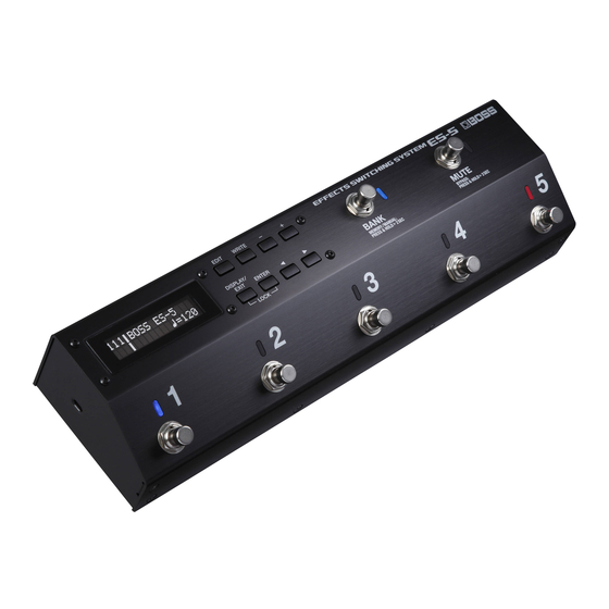
Main features
The ES-5 is a switching system that lets you connect effect pedals
and other effect units, and then store and recall up to 200 different
combinations of them.
It also provides a wide variety of external control functions for
controlling your amp and effects in real time.
2
2
4
5
5
5
6
6
6
6
6
7
7
7
8
8
8
8
9
9
9
12
12
13
13
13
13
13
13
13
13
13
14
15
15
15
16
16
17
18
18
19
19
20
20
20
21
21
21
Advertisement
Table of Contents

Related Manuals for Boss ES-5


Summary of Contents for Boss ES-5
-
Page 1: Table Of Contents
Owner’s Manual Main features The ES-5 is a switching system that lets you connect effect pedals and other effect units, and then store and recall up to 200 different combinations of them. It also provides a wide variety of external control functions for controlling your amp and effects in real time. -
Page 2: Panel Descriptions
RETURN 1–5 jacks. This is a connection in which an effect device is connected via send and return jacks. The ES-5 provides five effect loops, 1–5. Connect the SEND 1–5 jacks to the INPUT jack of each effect unit, and connect the OUTPUT jack of each effect unit to the RETURN 1–5 jacks. - Page 3 Panel Descriptions MIDI connectors EXT CTL jacks Connect an external MIDI device here to transmit and CTL 1/2, 3/4 jacks receive MIDI messages. These are control jacks for latch or The operation of the MIDI OUT/THRU connectors momentary operation. depends on the system settings (p. 12). You can use them to control various things such as switching amp channels or turning reverb on/off.
-
Page 4: Top Panel
You can also assign a different function to each switch (p. 10). Mutes the sound that is output from the ES-5. If mute is on, the indicator is lit blue. Hold down the switch for two seconds or longer to enter the bypass state (indicator lit red); the... -
Page 5: Attaching The Rubber Feet
“play mode. ” There are five types of play screen as shown in the following illustration, and you can use the [DISPLAY/EXIT] button to switch between them. Patch name screen 111 BOSS ES-5 Ì=120 Master BPM& 111 BOSS ES-5 Loop On/Off screen... -
Page 6: Saving/Recalling A Combination Of Effect Units (Memory Mode)
Saving/Recalling a Combination of Effect Units (Memory Mode) “Memory mode” is the mode in which you can save combinations of effect loops (patches) in the ES-5, and recall those saved settings. In contrast to memory mode, “manual mode” is the mode in which you can use the switches to turn each effect loop on/off manually. -
Page 7: Creating A Patch
Tips for Creating Patches (Sounds) Using the internal mixer is important in order to take advantage of the ES-5’s unique features, such as the ability to connect loops in parallel and use the Carryover function. Understanding how to use the mixer will make it even more enjoyable to create patches (sounds). -
Page 8: Changing The Effect Loop Settings
Creating a Patch Making a Parallel Connection Changing the Effect Loop Settings In the Loop Structure screen you can make the following settings. Example: Connect effect loops 2 and 3 in parallel 5 Change the connection order of the effect loops 5 Create a parallel connection Use the [ K ] [ J ] buttons to move the cursor to the merge 5 Specify Carryover... -
Page 9: Editing The Settings Of A Patch (Memory Edit Mode)
ON, OFF This is the output gain of the mixer. It is available only if Mixer Sw is ON. * If Mixer Sw is ON, the signal is output through the ES-5’s op- Mixer Gain amp. * If Input Buffer is off and all effect loops are off, turning Mixer Sw on might lower the volume. - Page 10 Creating a Patch Parameter Value/Explanation Parameter Value/Explanation Patch MIDI 1–8 EXP IN * When the Patch MIDI screen is displayed, pressing the [ENTER] button transmits all * If the Preference (p. 12) parameter is set to SYS, the screen indicates (SYS). of the MIDI messages that are assigned in Patch MIDI 1–8.
- Page 11 Creating a Patch Parameter Value/Explanation Select one of the following curves to specify the change produced by the internal pedal. Specifies the time for one cycle of the wave pedal. If this is set to a note value, a time Rate ª–˜, 0–100 corresponding to the “Master BPM”...
-
Page 12: Making Global Settings (System Setting)
Making Global Settings (System Setting) Settings that are shared by the entire ES-5 are called “system settings. ” Use the [ K ] [ J ] buttons to select a parameter, and then Press the [EDIT] button. press the [ENTER] button. -
Page 13: Patch/Data Operations (Utility)
1 ÅÃ 8 _ Transmitting Data to an External MIDI Device (Bulk Dump) With the ES-5, you can use Exclusive messages to set another ES-5 to the same settings or to save settings to MIDI sequencers and Bulk Dump other such devices. This transmission of data is referred to as bulk dump. -
Page 14: Restoring The Factory Settings (Factory Reset)
Patch/Data Operations (Utility) Restoring the Factory Settings (Factory Reset) “System settings” + “settings of the selected patch” can be returned to their factory-set condition (Factory Reset). Factory Reset * All data that is reset is lost. Frm:Sys To:855 _ Specify the highest patch that you want to reset, and press the [ENTER] button. Frm (From) Sys, 111–855 When the confirmation message appears, press the [ENTER] button once again. -
Page 15: Advanced Applications
Advanced Applications Adjusting the Level of Each Patch Parameter Value Reference NOTE Patch parameter 5 If you’re not using a parallel loop connection or Carryover, the mixer is Mixer Sw p. 9 placed immediately before the output. Mixer Gain -12 dB, -9 dB, -6 dB, -3 dB, 0 dB, +3 dB, +6 dB 5 If Input Buffer is off and all effect loops are off, turning Mixer Sw on might lower the volume. -
Page 16: Changing The Boss Dd-7'S Delay Time For Each Patch
Advanced Applications Changing the BOSS DD-7’s Delay Time for Each Patch Parameter Value Reference * If you connect to the BOSS PH-3’s EXP/CTL jack, you can change the Rate. Patch parameter ª – ˜ , 20–500 C1–4 p. 9 * Depending on the settings of C1–4, there might be cases in which System setting the delay time cannot follow. -
Page 17: Using The External Footswitch (Boss Fs-7'S A Switch) To Change The Delay Time
Advanced Applications Using the External Footswitch (BOSS FS-7’s A Switch) to Change the Delay Time Parameter Value Reference Patch parameter (CTL/EXP) CTL IN 2 Func CTL2 p. 10 Assign 1 Cate, Target E.CTL, CTL1 Min, Max OFF, ON Act L, Act H... -
Page 18: Applying Phaser Only While The Currently Selected Number Switch Is Held Down
Patch MIDI 1 p. 10 OFF, 0–127 at 1, but some devices start at 0. In this case, the memory number 1–128 that is one less than the ES-5’s PC setting is selected. MIDI-equipped effect unit (e.g., BOSS DD-500) Guitar Input... -
Page 19: Using The Expression Pedal To Control A Midi-Equipped Effect Unit
The sound of some wah or fuzz units may change if they are Parameter Value Reference connected after a buffer. Patch parameter Input Buffer p. 9 In this case, turn the ES-5’s input buffer (Input Buffer) off. Guitar Input Mixer DELAY PHASER DIST Buffer... -
Page 20: Appendix
Is “INT” or “WAV” set as the Src in Assign? the Assign Target changes automatically. On the ES-5, patches can be selected only when the Play screen is Is something other than the Play screen shown in the displayed. Press the [DISPLAY/EXIT] button several times to return p. -
Page 21: Main Specifications
USING THE UNIT SAFELY Main Specifications BOSS ES-5: Effects Switching System Modes Memory mode/Manual mode Loops Patch Memory Nominal Input Level INPUT, RETURN 1–5: -10 dBu Maximum Input Level INPUT, RETURN 1–5: +13 dBu Input Impedance INPUT: 1 MΩ (Buffer: On) Nominal Output Level SEND 1–5, OUTPUT, TUNER: -10 dBu...