Table of Contents
Advertisement
Quick Links
SERVICE MANUAL
Ver 1.0 2004.09
Sony Corporation
9-879-142-01
Personal Audio Company
2004I02-1
Published by Sony Engineering Corporation
© 2004.09
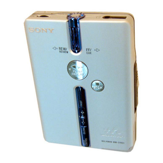
WM-EX651
Model Name Using Similar Mechanism
Tape Transport Mechanism Type
SPECIFICATIONS
Frequency response
Playback: 30 - 18 000 Hz
Output
Headphones (i jack)
Load impedance 8 - 300 Ω
Power requirements
• One rechargeable battery: 1.2V DC x 1
• One R6 (size AA) battery: 1.5 V DC x 1
For charging stand (DC IN 3 V jack)
• AC power adaptor
Dimensions (w/h/d)
Approx. 76.4 x 108.9 x 21.8 mm(excl. projecting parts and
controls)
Mass
Approx. 140 g (main unit only)
Supplied accessories
• Battery case (1)
• AC power adaptor (1)
• Charging stand (1)
• Stereo headphones or earphones with remote control (1)
• Rechargeable battery (NH-10WM, 1.2 V, 900 mAh (MIN), Ni- MH) (1)
• Carrying pouch (1)
• Rechargeable battery carrying case (1)
• AC plug adaptor (1) ("Sony world model" only)
Design and specifications are subject to change without notice.
E Model
Chinese Model
WM-EX631
MT-WMEX610-162
CASSETTE PLAYER
Advertisement
Table of Contents

Related Manuals for Sony WM-EX651


Summary of Contents for Sony WM-EX651
- Page 1 • Rechargeable battery (NH-10WM, 1.2 V, 900 mAh (MIN), Ni- MH) (1) • Carrying pouch (1) • Rechargeable battery carrying case (1) • AC plug adaptor (1) (“Sony world model” only) Design and specifications are subject to change without notice. CASSETTE PLAYER...
-
Page 2: Table Of Contents
COMPONENTS IDENTIFIED BY MARK 0 OR DOTTED LINE WITH MARK 0 ON THE SCHEMATIC DIAGRAMS AND IN THE PARTS LIST ARE CRITICAL TO SAFE OPERATION. REPLACE THESE COMPONENTS WITH SONY PARTS WHOSE PART NUMBERS APPEAR AS SHOWN IN THIS MANUAL OR IN SUPPLEMENTS PUBLISHED BY SONY. -
Page 3: Service Note
SERVICE NOTE [Service Mode] 3. FF, REW modes The service mode enables to operate the mechanism of WM-EX651 Check that the PRE-SET status is set. while the MAIN board is opened. Connect square wave or sine wave to TP53 (P. IN) and TP14 Rotation of the idler gear (A) (S side) is detected using the photo- (GND). - Page 4 WM-EX651 [ Slider (NR) ] [ Tape drive mechanism ] Tape drive mechanism in PLAY mode Gear (FR) (REW:Right side) Idler Gear (A) (S side) Gear (REEL) (S side) Slider (NR) Motor Pulley Cam Gear Gear (Y) F side R side...
-
Page 5: General
WM-EX651 SECTION 2 This section is extracted GENERAL from instruction manual. HOLD Plug in firmly. HOLD VOL* REW/REVIEW•FF/CUE REW (–) FF (+) bB PLAY/REPEAT** SOUND x STOP MODE SPEED CONTROL bB•x** OPEN * There is a tactile dot beside VOL on the main unit to show the direction to turn up the volume. -
Page 6: Disassembly
WM-EX651 SECTION 3 DISASSEMBLY • This set can be disassembled in the order shown below. 3-1. DISASSEMBLY FLOW MAIN BOARD BELT (F4) CASE ASSY MOTOR (CAPSTAN/REEL) (M901) (Page 7) (Page 6) (Page 7) (Page 8) PINCH LEVER CASSETTE ORNAMENT HOLDER (FS) -
Page 7: Main Board
WM-EX651 3-3. MAIN BOARD 3 Remove soldering (four points) from the leaf switch. 4 Remove soldering (two points) 2 Remove soldering (six points) from plunger solenoid. from the head flexible boards. S701 6 two screws 8 MAIN board 7 screw (M1.4) -
Page 8: Motor (Capstan/Reel) (M901)
WM-EX651 3-5. MOTOR (CAPSTAN/REEL) (M901) 1 two screws (M1.4) 2 motor (capstan/reel) (M901) 3-6. CASSETTE LID ASSY 2 screw (M1.4 × 2.0) 4 cassette lid assy 2 two screws (M1.4 × 2.0) 1 Open the cassette lid. 3 shaft... -
Page 9: Ornament (Open) Assy
WM-EX651 3-7. ORNAMENT (OPEN) ASSY 5 ornament (open) assy 4 two claws 3 boss 2 claw 1 two claws 3-8. HOLDER (FS) ASSY 2 shaft 7 bracket (cassette) assy 3 lock lever (B) 6 shaft 1 two screws (ib lock) 4 screw (M1.4) -
Page 10: Pinch Lever (N)/(R) Assy
WM-EX651 3-9. PINCH LEVER (N)/(R) ASSY 1 claw 2 Remove the pinch lever (R) assembly in the direction of the arrow. 4 Remove the pinch lever (N) assembly in the direction of the arrow. 3 claw holder (FS) assy 3-10. MAGNETIC HEAD (HP901) 1 two claws 2 Remove the magnetic head. -
Page 11: Mechanical Adjustment
WM-EX651 SECTION 4 SECTION 5 MECHANICAL ADJUSTMENT ELECTRICAL ADJUSTMENT MEMO PRECAUTION PRECAUTION 1. Clean the following parts with a denatured-alcohol-moistened 1. Specified voltage: 1.3 V (DC) swab: 2. Switch position playback head pinch roller HOLD rubber belts capstan 2. Demagnetize the playback head with a head demagnetizer. -
Page 12: Diagrams
WM-EX651 SECTION 6 DIAGRAMS NOTE FOR PRINTED WIRING BOARDS AND SCHEMATIC DIAGRAMS. 6-1. IC BLOCK DIAGRAMS For schematic diagrams. For printed wiring boards. IC301 TA2123AF (EL) Note: Note: • All capacitors are in µF unless otherwise noted. (p: pF) • X : parts extracted from the component side. -
Page 13: Block Diagrams
WM-EX651 6-2. BLOCK DIAGRAM RIPPLE FILTER BATT B+ Q301 AUDIO MASTER AMP IC301 RF OUT BASE RV301 HP901 J301 (PLAYBACK) IN-L POWER AMP L-CH OUT-L IN-L PREAMP PW OUT-L IN-L POWER AMP R-CH R-CH R-CH PW OUT-R DRV-L R-CH METAL... -
Page 14: Schematic Diagram - Main Section (1/2)
WM-EX651 6-3. SCHEMATIC DIAGRAM – MAIN SECTION (1/2) – • See page 12 for IC Block Diagrams. WM-EX651... -
Page 15: Schematic Diagram - Main Section (2/2)
WM-EX651 6-4. SCHEMATIC DIAGRAM – MAIN SECTION (2/2) – • See page 12 for IC Block Diagrams. • See page 11 for Waveforms. WM-EX651... -
Page 16: Printed Wiring Boards - Main Section (Side A)
WM-EX651 6-5. PRINTED WIRING BOARD – MAIN SECTION (SIDE A) – : Uses unleaded solder. D710 R726 D712 R717 X701 C703 MAIN BOARD (SIDEA) RV601 (TAPE SPEED) R603 R712 C708 D711 R703 C315 R701 C705 R832 C317 R746 C309 Q302... -
Page 17: Printed Wiring Boards - Main Section (Side B)
WM-EX651 6-6. PRINTED WIRING BOARD – MAIN SECTION (SIDE B) – : Uses unleaded solder. MAIN BOARD (SIDE B) S901-1 S901-2 TAPE DETECT ATS SW SWITCH TP34 TP35 SL301 SL302 TP55 TP60 C712 TP11 DRY BATTERY TP56 R714 SIZE "AA"... -
Page 18: Ic Pin Function Descriptions
WM-EX651 6-7. IC Pin Function Descriptions • IC701 ML63512-133TBZ020 (SYSTEM CONTROL) (MAIN BOARD) Pin No. Pin Name Description Pin No. Pin Name Description FF/REW CTL Motor speed control signal output “H”: FF/REW KO2 (OUT 2) Key matrix signal output FWD SW Direction switch signal input “L”: FWD... -
Page 19: Exploded Views
WM-EX651 SECTION 7 EXPLODED VIEWS NOTE: • Color Indication of Appearance Parts Example: • -XX, -X mean standardized parts, so they may KNOB, BALANCE (WHITE) . . . (RED) have some differences from the original one. ↑ ↑ • Items marked “*” are not stocked since they Parts of Color Cabinet’s Color... -
Page 20: Main Board Section
WM-EX651 7-2. MAIN BOARD SECTION S901 mechanism deck section-1 (MT-WMEX610-162) Ref. No. Part No. Description Remarks Ref. No. Part No. Description Remarks 3-375-114-71 SCREW 3-939-590-05 SCREW (IB LOCK) A-1078-710-A MAIN BOARD COMPLETE X-3377-717-5 BRACKET ASSY (/M) 2-188-347-01 GEAR (SPEED) 3-389-523-02 SCREW (IB LOCK) 3-345-648-71 SCREW (M1.4), TOOTHED LOCK... -
Page 21: Mechanism Deck Section-1
WM-EX651 7-3. MECHANISM DECK SECTION-1 (MT-WMEX610-162) M901 mechanism deck section-2 (MT-WMEX610-162) HP901 Ref. No. Part No. Description Remarks Ref. No. Part No. Description Remarks 3-046-789-01 SPRING (HDA) 3-220-035-01 BELT (F4) X-3378-354-5 HOLDER (FS) ASSY 3-029-282-12 GEAR (Y) 3-029-275-01 WASHER (STOPPER N) -
Page 22: Mechanism Deck Section-2
WM-EX651 7-4. MECHANISM DECK SECTION-2 (MT-WMEX610-162) PM901 Ref. No. Part No. Description Remarks Ref. No. Part No. Description Remarks 3-010-274-21 TABLE, REEL 3-029-284-13 LEVER, TRIGGER 3-010-954-01 SPRING (BT), COMPRESSION 3-029-281-01 GEAR, IDLER (B) X-3377-584-5 CHASSIS ASSY (FA) 3-029-283-02 GEAR, IDLER (A) -
Page 23: Electrical Parts List
WM-EX651 SECTION 8 ELECTRICAL PARTS LIST MAIN NOTE: The components identified by mark 0 • RESISTORS • Due to standardization, replacements in the or dotted line with mark 0 are critical All resistors are in ohms. parts list may be different from the parts for safety. - Page 24 WM-EX651 MAIN Ref. No. Part No. Description Remarks Ref. No. Part No. Description Remarks < JACK > R307 1-216-825-11 METAL CHIP 2.2K 1/10W R309 1-216-853-11 METAL CHIP 470K 1/10W J301 1-779-867-81 JACK (i) R601 1-216-837-11 METAL CHIP 1/10W R602 1-216-809-11 METAL CHIP 1/10W <...
- Page 25 WM-EX651 MAIN Ref. No. Part No. Description Remarks < SWITCH > S701 1-771-475-21 SWITCH, SLIDE (FWD t STOP t REV) S703 1-771-851-21 SWITCH, TACTILE (SMD) (x STOP) S704 1-771-851-21 SWITCH, TACTILE (SMD) (bB PLAY/REPEAT) S705 1-786-176-11 SWITCH, SLIDE (FF/CUE,REW/REVIEW) S707 1-572-922-11 SWITCH, SLIDE (.
-
Page 26: Revision History
WM-EX651 REVISION HISTORY Clicking the version allows you to jump to the revised page. Also, clicking the version at the upper right on the revised page allows you to jump to the next revised page. Ver. Date Description of Revision...