Table of Contents
Advertisement
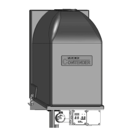
Installation
Manual
MH18082
This manual must only be used by a qualified heating installer/service technician. Read all instructions
in this manual before installing. Perform steps in the order given. Failure to comply could result in
severe personal injury, death or substantial property damage.
• Installation
• Startup
• Maintenance
• Parts
WARNING
Advertisement
Table of Contents

Related Manuals for Munchkin Gas-Fired Hot Water Circulating Heater

Summary of Contents for Munchkin Gas-Fired Hot Water Circulating Heater
- Page 1 Installation Manual MH18082 This manual must only be used by a qualified heating installer/service technician. Read all instructions in this manual before installing. Perform steps in the order given. Failure to comply could result in severe personal injury, death or substantial property damage. •...
- Page 2 If the information in this manual is not followed exactly, a fire or explo- sion may result causing property damage, personal injury or loss of life. Do not store or use gasoline or other flammable vapors and liquids in the vicinity of this or any other appliance. WHAT TO DO IF YOU SMELL GAS •...
-
Page 3: Table Of Contents
G. When Removing an Appliance from an Existing Common Vent System Part 4 – Prepare Munchkin Contender Heater ....... 11-12 A. - Page 4 G. Condensate Removal H. Final Checks Before Starting The Munchkin Contender Part 12 – Start-Up Procedure ..........53-55 A.
-
Page 5: Part 1: Product And Safety Information
PART 1: PRODUCT AND SAFETY INFORMATION SPECIAL ATTENTION BOXES The following defined terms are used throughout this manual to bring attention to the presence of hazards of various risk levels or to important information concerning the product. DEFINITIONS DANGER DANGER indicates an imminently hazardous situation which, if not avoided, will result in death or serious injury. - Page 6 Munckin Contender is used for space heating. When the Munchkin Contender is used to sup- ply potable water, it shall not be connected to any heating system or component(s) previously used with a non-potable water heating appli- ance.
-
Page 7: Part 2 - How The Heater Operates
The set point used for the control depends upon the programmed central heating curve. The slope of the heating curve can be changed by the installer of the Munchkin Contender in the sense that both turning points of the curve can be moved. The control monitors the... - Page 8 PART 2: HOW THE MUNCHKIN CONTENDER OPERATES powered and combustion air is flowing. 4. Swirl Plate System The Swirl Plate on the gas valve controls the air and gas flow into the burner, which will a s s u r e b e t t e r m i x i n g f o r i m p r o v e d combustion.
-
Page 9: Installations Must Comply With
PART 2: HOW THE MUNCHKIN CONTENDER OPERATES Super Stor Ultra Indirect Water Heater to get a fast recovery by prioritizing the flow at a higher temperature than may be needed for the central heating circuits (this will require two separate circulators). You must follow the... -
Page 10: Clearances For Service Access
4. If the new Munchkin Contender is to replace an existing heater, check for and correct any existing system problems such as: •... -
Page 11: Residential Garage Installation
The intake and exhuast venting methods are detailed in the Venting Section. Do not attempt to install the Munchkin Contender Heater using any other means. Be sure to locate the heater such that the air intake... -
Page 12: Part 4: Prepare Munchkin Contender Heater
A. REMOVE MUNCHKIN CONTENDER HEATER FROM BOX 1. The Munchkin Contender is easy to handle. Installation Manual GAS-FIRED HEATER in which the appliances remaining connected to the common venting system are located and other spaces of the building. -
Page 13: Munchkin Contender Wall Mounting Instruction
The wall must be vertically plumb and capable of carrying the weight of the Munchkin Contender and its related components. The building frame (studs) must be 16" on cen- ter. -
Page 14: Part 5: Munchkin Contender Piping
A low water cutoff may be required by state local code or some insurance companies. Check code requirements before installation of the Munchkin Contender Heater. It is also required that a low water cutoff be used if the heater is installed above the piping level. -
Page 15: Circulators
Temperature and Pressure gauge which allows the user to monitor the system pressure and outlet temperature from the Munchkin Contender. It is important to note that the Munchkin Contender has a minimal amount of pressure drop and must be calculated when sizing the circulators. -
Page 16: Circulator Sizing
Munchkin. CAUTION The Munchkin Contender should not be operated as a potable Hot Water Heater. 1. Connect the system return marked “Heater In”. 2. Connect the system supply marked “Heater Out”. -
Page 17: Fill And Purge Heating System
PART 5: MUNCHKIN CONTENDER PIPING The chart below represents the various system temperatures and their respective flows and friction loss through the Munchkin Contender which will aid circulator selection. 20˚ t 25˚ t Friction Flow Friction Feet Feet Model MC-50 6.5'... -
Page 18: Zoning With Zone Valves
MUNCHKIN CONTENDER PIPING CAUTION It is highly recommended that you carefully follow the glycol manufacturer’s recommended concentrations, expansion requirements and maintenance recommendations (pH additive breakdown, inhibitor reduction, etc.). You must carefully figure the additional friction loss in the system as well as the reduction in heat transfer co-efficients. -
Page 19: Contender Piping Details
(w/ integral check valve) pressure reducing valve diff. pressure bypass anti-scald mixing valve temperature /pressure gauge 3-way motorized mixing valve Munchkin Contender Heater 4-way motorized mixing valve purging valve pressure relief valve backflow preventer float-type air vent union DHW temperature sensor... - Page 20 The anti-scald mixing valve is recommended if the DHW temperature is set above the factory setting of 119˚F. Install a minimum of 12 diameters of straight pipe upstream of all circulators. Winterization: When winterizing the Munchkin Contender, put a drain valve on both the supply and return between the union and the shut-off connection.
- Page 21 The anti-scald mixing valve is recommended if the DHW temperature is set above the factory setting of 119˚F. Install a minimum of 12 diameters of straight pipe upstream of all circulators. Winterization: When winterizing the Munchkin Contender, put a drain valve on both the supply and return between the union and the shut-off connection.
-
Page 22: Space Heating Mode
The anti-scald mixing valve is recommended if the DHW temperature is set above the factory setting of 119˚F. Install a minimum of 12 diameters of straight pipe upstream of all circulators. Winterization: When winterizing the Munchkin Contender, put a drain valve on both the supply and return between the union and the shut-off connection. - Page 23 The anti-scald mixing valve is recommended if the DHW temperature is set above the factory setting of 119˚F. Install a minimum of 12 diameters of straight pipe upstream of all circulators. Winterization: When winterizing the Munchkin Contender, put a drain valve on both the supply and return between the union and the shut-off connection.
- Page 24 The anti-scald mixing valve is recommended if the DHW temperature is set above the factory setting of 119˚F. Install a minimum of 12 diameters of straight pipe upstream of all circulators. Winterization: When winterizing the Munchkin Contender, put a drain valve on both the supply and return between the union and the shut-off connection.
- Page 25 The anti-scald mixing valve is recommended if the DHW temperature is set above the factory setting of 119˚F. Install a minimum of 12 diameters of straight pipe upstream of all circulators. Winterization: When winterizing the Munchkin Contender, put a drain valve on both the supply and return between the union and the shut-off connection.
-
Page 26: Part 6 - Contender Piping With Optional Vision 1 System
PART 6. MUNCHKIN CONTENDER PIPING WITH OPTIONAL VISION I SYSTEM A. VISION I SYSTEM PIPING It is important that the system piping is done correctly when using the Vision 1 System. Follow the piping diagrams 2A through 3G when piping your Munchkin Contender with Vision I. - Page 27 The anti-scald mixing valve is recommended if the DHW temperature is set above the factory setting of 119˚F. Install a minimum of 12 diameters of straight pipe upstream of all circulators. Winterization: When winterizing the Munchkin Contender, put a drain valve on both the supply and return between the union and the shut-off connection.
- Page 28 The anti-scald mixing valve is recommended if the DHW temperature is set above the factory setting of 119˚F. Install a minimum of 12 diameters of straight pipe upstream of all circulators. Winterization: When winterizing the Munchkin Contender, put a drain valve on both the supply and return between the union and the shut-off connection.
- Page 29 The anti-scald mixing valve is recommended if the DHW temperature is set above the factory setting of 119˚F. Install a minimum of 12 diameters of straight pipe upstream of all circulators. Winterization: When winterizing the Munchkin Contender, put a drain valve on both the supply and return between the union and the shut-off connection.
- Page 30 The anti-scald mixing valve is recommended if the DHW temperature is set above the factory setting of 119˚F. Install a minimum of 12 diameters of straight pipe upstream of all circulators. Winterization: When winterizing the Munchkin Contender, put a drain valve on both the supply and return between the union and the shut-off connection.
- Page 31 The anti-scald mixing valve is recommended if the DHW temperature is set above the factory setting of 119˚F. Install a minimum of 12 diameters of straight pipe upstream of all circulators. Winterization: When winterizing the Munchkin Contender, put a drain valve on both the supply and return between the union and the shut-off connection.
- Page 32 The anti-scald mixing valve is recommended if the DHW temperature is set above the factory setting of 119˚F. Install a minimum of 12 diameters of straight pipe upstream of all circulators. Winterization: When winterizing the Munchkin Contender, put a drain valve on both the supply and return between the union and the shut-off connection.
- Page 33 The anti-scald mixing valve is recommended if the DHW temperature is set above the factory setting of 119˚F. Install a minimum of 12 diameters of straight pipe upstream of all circulators. Winterization: When winterizing the Munchkin Contender, put a drain valve on both the supply and return between the union and the shut-off connection.
- Page 34 The anti-scald mixing valve is recommended if the DHW temperature is set above the factory setting of 119˚F. Install a minimum of 12 diameters of straight pipe upstream of all circulators. Winterization: When winterizing the Munchkin Contender, put a drain valve on both the supply and return between the union and the shut-off connection.
- Page 35 The anti-scald mixing valve is recommended if the DHW temperature is set above the factory setting of 119˚F. Install a minimum of 12 diameters of straight pipe upstream of all circulators. Winterization: When winterizing the Munchkin Contender, put a drain valve on both the supply and return between the union and the shut-off connection.
- Page 36 The anti-scald mixing valve is recommended if the DHW temperature is set above the factory setting of 119˚F. Install a minimum of 12 diameters of straight pipe upstream of all circulators. Winterization: When winterizing the Munchkin Contender, put a drain valve on both the supply and return between the union and the shut-off connection.
-
Page 37: Part 7 - Venting Combustion Air And Condensate Removal
PART 7: VENTING, COMBUSTION AIR & CONDENSATE REMOVAL DANGER Munchkin Contender Heater must be vented as detailed in Venting section Part 7. Ensure the exhaust and intake piping comply with these instructions regarding vent system. Inspect finished combustion air intake and... -
Page 38: Exhaust Vent And Intake Air Vent Sizing
PART 7: VENTING, COMBUSTION AIR & CONDENSATE REMOVAL Provide 4 feet horizontal clearance from electrical meters, gas meters, gas regulators and relief equipment. In no case shall the exit terminal be above or below the aforementioned equipment unless the 4 foot horizontal distance is maintained. - Page 39 GAS-FIRED HEATER EXHAUST PIPING AROUND OBSTRUCTIONS (SUGGESTED SETUP FOR PIPING AROUND BEAMS IN ORDER TO ELIMINATE CONDENSATION) THE INTAKE VENT CAN BE ROTATED INTO ANY POSITION TOP VIEW Installation Manual 1/4" NPT X 1/2" HOSE BARB 1/4" NPT X 1/2" HOSE BARB BUILDING STRUCTURE...
- Page 40 Location of exit terminals of mechanical draft and direct-vent venting systems. (Reference: National Fuel Gas Code ANSI Z223.1/NFPA 54 2002). Fig. 7-1 Fig. 7-2 Multiple Vent Spacing* *Note: Exhaust must extend out 1 foot Fig. 7-3 Multiple Stainless Steel Horizontal Vent Kit Installation – Front View Installation Manual GAS-FIRED HEATER Figure 7-4: Multiple Heater Installations...
- Page 41 None TEL = Total Equivalent Length INSTALLATION 1. On the Munchkin Contender the 2" exhaust vent connection is located on the top, right side of the unit and the air intake is on the top, left side. Sealant or adhesive is required for all fittings.
-
Page 42: Heater Removal From A Common Vent System
4 foot intervals to prevent sagging of the pipe where condensate may form. 7. Do not use the Munchkin Contender to support any piping. 8. A screened straight coupling is provided with the heater for use as an outside exhaust termination. -
Page 43: Condensate Removal System
Munchkin Contender is lower than the drain, you must use a condensate removal pump (kit P/N 554200 available from Heat Transfer Products, Inc.) A condensate filter, if required by... -
Page 44: Diagrams For Sidewall Venting
I. DIAGRAMS FOR SIDEWALL VENTING TOP VIEW EXTERIOR WALL SUPPORT BRACKETS MUST BE USED ON ALL HORIZONTAL AND VERTICAL PIPING RIGHT SIDE VIEW Fig. 7-9 2” sidewall vent with tee (intake) and coupling (exhaust) **Important Note: All vent pipes must be glued, properly supported, and the exhaust must be pitched a minimum of a 1/4"... - Page 45 EXHAUST (STRAIGHT COUPLING) 10'-0" MIN. INTAKE (TEE) SUPPORT BRACKETS MUST BE USED ON ALL HORIZONTAL AND VERTICAL PIPING RIGHT SIDE VIEW Fig. 7-12 2" roof vent with tee (intake) & coupling (exhaust) NOTE: When placing support brackets on vent piping, the first bracket must be within 1 foot of the appliance and the balance at 4 foot invervals on the vent pipe.
-
Page 46: Part 8: Gas Piping
National Fuel Gas Code. You must ensure that the entire gas line to the connection at the Munchkin Contender is no smaller than ¾". Once all the inspections have been per- formed, the piping must be leak tested. If the... -
Page 47: Gas Piping
PART 8: GAS PIPING (CONTINUED) Contender. It is very important that the gas line is properly purged by the gas supplier or utility. Failure to properly purge the lines or improper line sizing, will result in ignition failure. This problem is especially noticeable in NEW LP installations and also in empty tank situations. -
Page 48: Part 9: Field Wiring
Code Part 1, and any local codes. B. FIELD WIRING For you convenience we have located the electri- cal connection of the Munchkin Contender on the Installation Manual GAS-FIRED HEATER front right hand side of the unit. The electrical junc- tion box has a 24 volt terminal compartment and 120 volt terminal compartment. - Page 49 PART 9: FIELD WIRING Fig. 9-1 Fig. 9-2 GAS-FIRED HEATER (CONTINUED) Fig. 9-3 Fig. 9-4 Installation Manual...
- Page 50 Installation Manual GAS-FIRED HEATER PART 9: FIELD WIRING (CONTINUED) Fig. 9-5...
-
Page 51: Part 10: Field Wiring - Vision 1 Option
Central Heating Circuit. Once the Water Heater is satisfied, the heater will then switch back to the Central Heating Circuit only if there is a call for heat, otherwise the Munchkin Contender will then shut down. Indirect Circulator... -
Page 52: Part 11. Start-Up Preparation
Throroughly clean and flush any system that has has used glycol before installing the new Contender Contender Heater. Provide Munchkin Contender Heater owner with a material safety data sheet (MSDS) on the fluid used. 1. Determine freeze protection fluid quantity using total system water content, following fluid manufacturer’s instructions. -
Page 53: Purge Air From Water System
Repeat with remaining vents. Refill to correct pressure. E. CHECK FOR GAS LEAKS WARNING Before starting the Munchkin Contender, and during initial operation, smell near the floor and around the heater for gas odorant or any unusual odor. Remove heater front door and smell interior of heater enclosure. -
Page 54: Condensate Removal
5. The Munchkin Contender Heater shall be installed so the gas ignition system components are protected from water (dripping, spraying, rain, etc.) during appliance operation and service (circulator replacement, condensate trap, control replacement, etc.) -
Page 55: Operating Instructions
The {S1/-} button will decrease the temperature while the {S2/+} will increase the temperature of the Munchkin. The temperature of the heater can be set as low as 50 Degrees and as high 180 Degrees. These ranges are your maximum and minimum ranges of the heater. -
Page 56: Test Mode
A. PROGRAMMING THE VISION I OPTION The Vision I option allows the installer to set sys- tem limits and the heat curve for the Munchkin Contender. These system limits should not be changed by the user. It is important to document... -
Page 57: Vision I Program Navigation
Listed below are the vari- ety of functions the installer can program into the Vision I System. CAUTION The Munchkin Contender cannot be programmed while there is a call for heat. NOTE: See Chart 13-1 in Part 13 to set outdoor reset curve. - Page 58 — cascade slave) (Not currently used.) Interface Board Activation 0 = not active 1 = active WARNING: Never change the de- fault setting without the Munchkin Interface Board installed.** Interface Board Function 0 = Building Management 1 = Enables Tekmar Modulating control.
- Page 59 PART 13: START-UP PROCEDURES WITH THE VISION 1 OPTION CENTRAL HEATING CURVE Factory Default 201˚ FUNCTION 9 DEFAULT RESET CURVE FUNCTION 11 5˚ OUTSIDE TEMPERATURE (F) Fig. 13-1 CONTROL PROGRAM REFERENCE CHART Function Fig. 13-3 GAS-FIRED HEATER 68˚ Fig. 13-2 Default Setting Programmed Setting No change allowed...
-
Page 60: Part 14: Troubleshooting
PART 14: TROUBLESHOOTING A. MUNCHKIN ERROR CODE An error code may occur in the installation of the Munchkin Contender. This condition may lead to a lock out condition of the controller, which will need to be manually reset through the S4/Reset button. These temporary codes... - Page 61 PART 14: TROUBLESHOOTING Table 14-2: 925 Control Board FAULT Codes Code Description High Limit Exceeded. Vent Temperature Limit Switch Exceeded. Interrupted or Shorted Supply (Outlet) Thermister. Interrupted or Shorted Return (Inlet) Thermister. Supply (Outlet) Temperature exceeds 230°F . Return (Inlet) Temperature Exceeded 230°F .
-
Page 62: Part 15: Maintenance
PART 14: TROUBLESHOOTING Resistance Tables Outdoor Sensor (7250P-319) Outside Temperature (°F) Resistance (ohms) Fig. 14-2 NOTE: If receiving an F09 fault code, check t h e g a p s p a c i n g between points on the electrode by holding two quarters together a n d s l i d i n g t h e m... -
Page 63: Combustion Chamber Coil Cleaning Instructions
“CLR” (available at most hardware stores) – Gloves, eye protection 1. Shut down the Munchkin Contender by using the following steps: a. Close the gas valve, shut down the unit and wait for the unit to be cool to the touch b. - Page 64 PART 15: MAINTENANCE Item Description Composite Module 7500P-010 (MC50) 7500P-012 (MC80) 7500P-014 (MC99/MC120) Ceramic Target Wall 7250P-160 Burner Door Ceramic Refractory 7500P-076 Burner Door (w/Nuts) 7500P-078 Nuts - M6 (Burner Door) 7500P-067 NIT Burner 7500P-015 (MC50) 7500P-016 (MC80) 7500P-017 (MC99/MC120) Gasket (Burner) 7500P-074 Air/Gas Channel (w/Torx Screws)
- Page 65 PART 15: MAINTENANCE Fig. 15-2 GAS-FIRED HEATER (CONTINUED) Item # Concentric Flue Outlet (w/Gasket) Gasket (Concentric Flue Outlet) PVC Pipe (2" Sch. 40 - 12" Long) Flue Adapter Flue ECO O-Ring (S.S. Barbed Fitting) S.S. Barbed Fitting Water Pressure Switch O-Ring (Water Pressure Switch) Clear Tubing 3/16 ID x 5/16 OD Water Pressure Switch Adapter...
- Page 66 PART 15: MAINTENANCE Item Description Cover Filler Plate(w/Screws) Blocked Vent Pressure Switch Screws 8-32x3/8 (Blocked Vent Pressure Switch) Control Board (w/Screws) 5 Pin Wiring Harness (location) 9 Pin Wiring Harness (location) Low Voltage Wiring Harness (location) Screws # 6 x 1/2 - Control Board Clamp -Module to Bracket (w/Screws) 10 Screws M4x6 (Clamp) 11 CTB-27ST Spring Clamp (Condensate Hose) 7250P-012...
- Page 67 Installation Manual GAS-FIRED HEATER...
- Page 68 Installation Manual GAS-FIRED HEATER...
- Page 69 Installation Manual GAS-FIRED HEATER...
- Page 70 MAINTENANCE NOTES...
- Page 71 MAINTENANCE NOTES...
- Page 72 © 2007, 2006 Heat Transfer Products, Inc. LP-171 REV. 3/20/07...