Pioneer XV-DV55 Service Manual
Dvd tuner
Hide thumbs
Also See for XV-DV55:
- Operating instructions manual (120 pages) ,
- Servise manual (94 pages) ,
- Operating instructions manual (120 pages)
Table of Contents
Advertisement
DVD TUNER
XV-DV55
THIS MANUAL IS APPLICABLE TO THE FOLLOWING MODEL(S) AND TYPE(S).
Model
Type
XV-DV55
AUCXJ
O
ADXJ/RA
O
APWXJ
O
AVXJ
O
AYXJ
O
This product is component of system.
Component
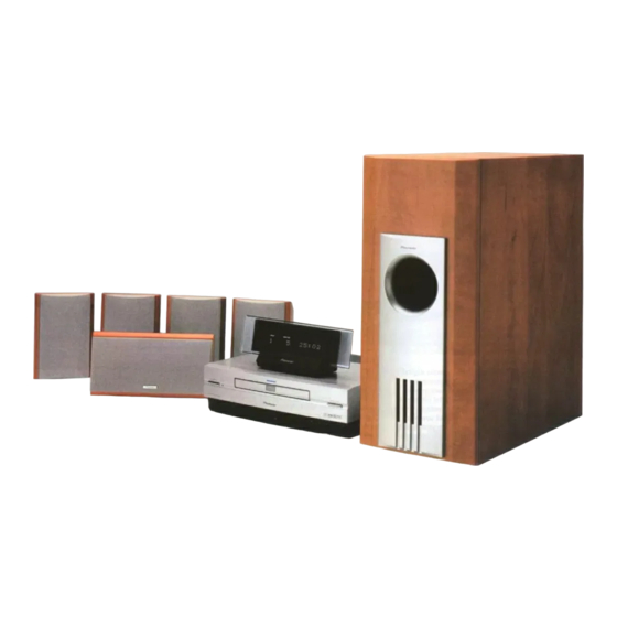
DVD SURROUND SYSTEM
DVD TUNER
POWERED SUBWOOFER
SATELLITE SPEAKER
CONTENTS
1. SAFETY INFORMATION ....................................... 2
2. EXPLODED VIEWS AND PARTS LIST ................. 4
4. PCB CONNECTION DIAGRAM ........................... 41
5. PCB PARTS LIST ................................................ 54
6. ADJUSTMENT ..................................................... 61
7. GENERAL INFORMATION .................................. 62
7.1 DIAGNOSIS ................................................... 62
7.1.1 SELF-DIAGNOSTIC FUNCTION OF PICKUP
DEFECTIVE ............................................. 62
PIONEER CORPORATION
PIONEER ELECTRONICS SERVICE, INC. P.O. Box 1760, Long Beach, CA 90801-1760, U.S.A.
PIONEER ELECTRONIC NV Haven 1087, Keetberglaan 1, 9120 Melsele, Belgium
PIONEER ELECTRONICS ASIACENTRE PTE. LTD. 253 Alexandra Road, #04-01, Singapore 159936
c
PIONEER CORPORATION 2000
Power Requirement
AC power supplied from power trans former's
secondary of other system component.
AC power supplied from power trans former's
secondary of other system component.
AC power supplied from power trans former's
secondary of other system component.
AC power supplied from power trans former's
secondary of other system component.
AC power supplied from power trans former's
secondary of other system component.
Model
XV-DV55
S-DV55SW-K
S-DV55ST-K
4-1, Meguro 1-chome, Meguro-ku, Tokyo 153-8654, Japan
Regional restriction
codes(Region N0.)
1
1
4
2
2
Service Manual
-
-
RRV2309
RRV2310
RRV2306
7.1.2 TEST POINTS LOCATIONS ..................... 63
7.1.3 TEST MODE SCREEN DISPLAY ........... 64
7.1.4 POWER ON SEQUENCE ......................... 66
7.1.5 TROUBLE SHOOTING ............................ 67
7.1.6 SINGLE OPERATION METHOD .............. 68
7.1.7 TEST MODE (FOR SERVICE) ................. 69
7.1.8 ERROR CODE ......................................... 70
7.1.9 DISASSEMBLY ........................................ 74
7.2 PARTS ........................................................... 77
7.2.1 IC ............................................................. 77
8. PANEL FACILITIES AND SPECIFICATIONS ....... 90
ORDER NO.
RRV2309
Remarks
Remarks
This service manual
T – ZZY JUNE 2000 Printed in Japan
Advertisement
Table of Contents

Related Manuals for Pioneer XV-DV55


Summary of Contents for Pioneer XV-DV55
- Page 1 PIONEER CORPORATION 4-1, Meguro 1-chome, Meguro-ku, Tokyo 153-8654, Japan PIONEER ELECTRONICS SERVICE, INC. P.O. Box 1760, Long Beach, CA 90801-1760, U.S.A. PIONEER ELECTRONIC NV Haven 1087, Keetberglaan 1, 9120 Melsele, Belgium PIONEER ELECTRONICS ASIACENTRE PTE. LTD. 253 Alexandra Road, #04-01, Singapore 159936 PIONEER CORPORATION 2000 T –...
-
Page 2: Safety Information
The use of a substitute replacement component which does Leakage 0.5mA current Device not have the same safety characteristics as the PIONEER tester under recommended replacement one, shown in the parts list in test this Service Manual, may create shock, fire, or other hazards. - Page 3 XV-DV55 WARNING THE AEL(ACCESSIBLE EMISSION LEVEL) OF THE LASER POWER OUTPUT IS LESS THAN CLASS 1 BUT THE LASER COMPONENT IS CAPABLE OF EMITTING RADIATION EXCEEDING THE LIMIT FOR CLASS1. A SPECIALLY INSTRUCTED PERSON SHOULD DO SERVICING OPERATION OF THE APPARATUS.
-
Page 4: Exploded Views And Parts List
XV-DV55 2. EXPLODED VIEWS AND PARTS LIST • NOTES: Parts marked by "NSP" are generally unavailable because they are not in our Master Spare Parts List. • mark found on some component parts indicates the importance of the safety factor of the part. - Page 5 XV-DV55 (1) PACKING PARTS LIST Mark No. Description Part No. Mark No. Description Part No. Display Cable (10P Din) ADE7014 Warranty Card See Contrast table (2) Control Cable A (Blue) (10P) See Contrast table (2) AM Loop Antenna ATB7009 Control Cable B (Black) (12P)
- Page 6 XV-DV55 2.2 EXTERIOR Refer to "2.3 LOADING MECHANISM ASSY". To LOAB Assy CN101 40, 44 38 NOTE NOTE Parts of No.38 do no service part partially of the PCB board of AUDIO Assy.
- Page 7 XV-DV55 • EXTERIOR PARTS LIST Mark No. Description Part No. Mark No. Description Part No. AJKB ASSY See Contrast table (2) Lens Holder(Pls) AMR7320 MOTHER ASSY See Contrast table (2) Tray Panel(Pls) AAN7199 KEYB ASSY AWU7675 Bottom Base(Pls) AMA7019 REGULATOR ASSY...
- Page 8 XV-DV55 2.3 LOADING MECHANISM ASSY To DVDM Assy Refer to "2.4 TRAVERSE MECHANISM ASSY-S". To DVDM Assy To DVDM Assy LOADING MECHANISM ASSY PARTS LIST Mark No. Description Part No. Mark No. Description Part No. Loading Motor Assy VXX2505 1 Traverse Mechanism Assy-S VXX2653 DC Motor / 0.3W (LOADING) PXM1027...
- Page 9 XV-DV55 2.4 TRAVERSE MECHANISM ASSY-S • Top View DVDM Assy TRAVERSE MECHANISM ASSY-S PARTS LIST Mark No. Description Part No. Mark No. Description Part No. SMEB Assy VWG2048 Hook VNL1770 FGSB Assy VWG2009 FFC Holder VNL1802 Motor (CARRIAGE) VXM1079 Mechanism Base...
- Page 10 XV-DV55 2.5 DISPLAY UNIT • DISPLAY UNIT PARTS LIST Mark No. Description Part No. FLDP ASSY AWU7678 CNB ASSY AWU7679 AEB7090 Window (Pls) AAK7785 Fl Filter(Pls) AEC7272 Display Panel(Pls) AMB7704 Display Cover(Pls) AMC7044 Screw BPZ30P080FMC Screw PSC30P080FNI...
- Page 11 XV-DV55...
-
Page 12: Block Diagram And Schematic Diagram
XV-DV55 3. BLOCK DIAGRAM AND SCHEMATIC DIAGRAM 3.1 BLOCK DIAGRAM 36/16M (24P) (24P) AODAI(AC3) Spindle OEIC ADAO RF IC Motor SD0-SD7 MPEG2 DSPRF 57-60 78,80-84 DECODER DECODER VOUT 63-66 86,87 LA9701M BY CHIP AV-1 YOUT SREQ IC12 IC18 COUT XSACK... -
Page 13: Tuner Module
XV-DV55 (30P) (30P) H.P. AMP CN8502 H.P. VOL JA3901 HP OUT IC3901 M + 6V IC3902 M62429FP NJM4560M +12V +2.5V VD+3DVD +3.3V JA5101 PQ025EZ5MZP COAXCIAL INPUT IC8521 DIGITAL INPUT +2.5V SELECTOR JA5101 OPTICAL INPUT IC5101 TC74HC153AF AODAI(AC3) AODAI(AC3) AODAI X5501(10MHz) - Page 14 XV-DV55 3.2 OVERALL CONNECTION DIAGRAM 1/3- DVDM ASSY : RF SIGNAL ROUTE (AWX7724) : FOCUS SERVO LOOP LINE CN15 : TRACKING SERVO LOOP LINE : SLIDER SERVO LOOP LINE CN8502 CN8501 PICKUP ASSY (VWY1055) LOADING MECHANISM ASSY (VWT1174) TRAVERSE MECHANISM...
- Page 15 XV-DV55 Note : When ordering service parts, be sure to refer to "EXPLODED VIEWS and PARTS LIST" or "PCB PARTS LIST". TUNER MODULE (AUCXJ, ADXJ/RA, APWXJ: AXQ7228) (AVXJ,AYXJ: AXQ7229) REGULATOR ASSY (AWU7676) CN5021 CN5011 CN3651 CN5701 CN5002 1/2- CN5001 MOTHER ASSY...
- Page 16 XV-DV55 3.3 DVDM ASSY (1/3) DVDM ASSY (AWX7724) CHECKER CHIP (DVD) (DVD) (CD) RF IC DKN1193 S3B-PH-SM3 SPDL & FTS DRIVER CN101 S2B-PH-SM3 CN202 VKN1763...
- Page 17 XV-DV55 : The power supply is shown with the marked box. : RF SIGNAL ROUTE : ROM DATA SIGNAL ROUTE : FOCUS SERVO LOOP LINE : TRACKING SERVO LOOP LINE : SLIDER SERVO LOOP LINE LANDMARK for CHECKER (DVD) (DVD)
- Page 18 XV-DV55 3.4 DVDM ASSY (2/3) DVDM ASSY (AWX7724) WORK SRAM (1M) KM68V1000CLT-7L FLASH MEMORY (4M) AWY7005 4M DRAM BY CHIP (DVD)
- Page 19 XV-DV55 : RF SIGNAL ROUTE : ROM DATA SIGNAL ROUTE 1/3, 3/3 : AUDIO SIGNAL ROUTE 1/3, 3/3 SYSTEM CONTROL CPU VKN1626 CN8502 RN1911 : The power supply is shown with the marked box.
- Page 20 XV-DV55 3.5 DVDM ASSY (3/3) DVDM ASSY (AWX7724) AV-1 14 17 13 16 12 15 16M SDRAM (VCB)
- Page 21 XV-DV55 : AUDIO SIGNAL ROUTE : ROM DATA SIGNAL ROUTE (VCB) : V/CB SIGNAL ROUTE : Y SIGNAL ROUTE : C SIGNAL ROUTE CLOCK GENERATOR (VCB) (VCB) CN15 VKN1763 (VCB) (VCB) CN8501...
- Page 22 XV-DV55 3.6 REGULATOR and MOTHER ASSYS (1/3) REGULATOR ASSY (AWU7676) CAUTION : FOR CONTINUED PROTECTION AGAINST RISK OF FIRE. REPLACE WITH SAME TYPE NO. AEK7059 MFD. BY LITTELFUSE INC. FOR IC5001. CAUTION : FOR CONTINUED PROTECTION AGAINST RISK OF FIRE.
- Page 23 XV-DV55 : The power supply is shown with the marked box. VFDP MOTHER ASSY (AUCXJ: AWU7674) CN3651 (ADXJ/RA: AWU7650) (APWXJ:AWU7651) (AVXJ,AYXJ: AWU7648)
- Page 24 XV-DV55 3.7 MOTHER ASSY (2/3) MOTHER ASSY CN5621 (AUCXJ: AWU7674) (ADXJ/RA: AWU7650) (APWXJ:AWU7651) (AVXJ,AYXJ: AWU7648) CN5501 CN8501 (DVD) (DVD) (DVD) (DVD) R5592 R5594 R5597 AUCXJ Not used Not used Not used ADXJ/RA Not used Not used APWXJ Not used Not used...
- Page 25 XV-DV55 AUCXJ ADXJ/RA AVXJ APWXJ AYXJ C3913 1000p 10000p C3914 (DVD) CN5701 AVXJ, AYXJ only except AUXJ, AVXJ CN5503 (DVD) (DVD) (DVD) CN5504 (DVD) CN5505 CN5506 : AUDIO SIGNAL ROUTE (DVD) : DVD AUDIO SIGNAL ROUTE CN5204 CN5203 8, 9, 10,13,14,15...
- Page 26 XV-DV55 3.8 MOTHER ASSY (3/3) JA5301 VTL1087 (DVD) JA5101 VTL1112 JA5102 JA5103 8, 9, 10, 13, 14, 15 AVPART (DVD) (DVD)
- Page 27 XV-DV55 MOTHER ASSY (AUCXJ: AWU7674) (ADXJ/RA: AWU7650) (APWXJ:AWU7651) (AVXJ,AYXJ: AWU7648) JA5351 C5376 330p C5382 330p AUCXJ ADXJ/RA AVXJ APWXJ AYXJ L5371- L5374 VTL1087 VTL1081 L5377- L5380 (DVD) JA5151 : AUDIO SIGNAL ROUTE (DIGITAL) (DVD) : DVD AUDIO SIGNAL ROUTE : VIDEO SIGNAL ROUTE...
- Page 28 XV-DV55 3.9 AJKB and TRADE ASSYS JA5201 VIDEO1 OUT (DVD) (TA) VIDEO1 IN VIDEO2 IN JA5202 AUDIO2 IN AUCXJ ADXJ APWXJ AVXJ AYXJ AUDIO1 OUT C5203, C5204 100p 1000p C5209, C5210 AUDIO1 IN CN5201 CN5202 TRADE ASSY (AWU7677) CN5203 CN5505...
- Page 29 XV-DV55 (DVD) (TA) CN5207 AJKB ASSY (AUCXJ, ADXJ/RA, APWXJ: AWU7641) (AVXJ,AYXJ: AWU7670) CN5507 CN5206 : The power supply is shown with the marked box. CN5205 : AUDIO SIGNAL ROUTE (DVD) : DVD AUDIO SIGNAL ROUTE (TX) : TUNER AUDIO SIGNAL ROUTE...
- Page 30 XV-DV55 3.10 DSP ASSY (1/2) CN3701 CN3702 CN3703 DSP ASSY AUCXJ, ADXJ, APWXJ (AUCXJ, ADXJ/RA, APWXJ: AWU7640) only (AVXJ,AYXJ: AWU7669) : The power supply is shown with the marked box.
- Page 31 XV-DV55 : AUDIO SIGNAL ROUTE (FL) : FL AUDIO SIGNAL ROUTE (SL) : SL AUDIO SIGNAL ROUTE : C AUDIO SIGNAL ROUTE : AUDIO SIGNAL ROUTE (DIGITAL)
- Page 32 XV-DV55 3.11 DSP ASSY (2/2) (FL) (FL) (FL) (SL) (SL) (SL)
- Page 33 XV-DV55 (FL) (FL) (FL) (FL) : FL AUDIO SIGNAL ROUTE (SL) : SL AUDIO SIGNAL ROUTE : C AUDIO SIGNAL ROUTE (SL) (SL) (SL) CN8901 (FL) (SL) DSP ASSY (AUCXJ, ADXJ/RA, APWXJ: AWU7640) (AVXJ,AYXJ: AWU7669)
- Page 34 XV-DV55 3.12 TUNER MODULE (AXQ7228) FM/AM TUNER MODULE (AXQ7228) (AUCXJ, ADXJ/RA, APWXJ) FM FRONT END (FM) (FM) (FM) (FM) (FM) (AM) (AM) (AM) MW RF TUNING BLOCK (FM) (AM) OSC : 981 - 2052kHz 9k step...
- Page 35 XV-DV55 : The power supply is shown with the marked box. (TX) : AUDIO SIGNAL ROUTE (TUNER) (AM) : AM SIGNAL ROUTE (FM) : FM SIGNAL ROUTE (AM) (TX) (FM) (TX) (TX) CN201 (TX) (FM) (FM) (TX) (AM) L201 ATE7003...
- Page 36 XV-DV55 3.13 TUNER MODULE (AXQ7229) FM/AM TUNER MODULE (AXQ7229) (AVXJ, AYXJ) FM FRONT END (FM) (FM) (FM) (FM) (FM) (AM) (AM) (AM) MW RF TUNING BLOCK (FM) (AM) OSC : 981 - 2052kHz 9k step...
- Page 37 XV-DV55 : The power supply is shown with the marked box. (TX) : AUDIO SIGNAL ROUTE (TUNER) (AM) : AM SIGNAL ROUTE (FM) : FM SIGNAL ROUTE (AM) (TX) (FM) (TX) (TX) (TX) CN201 (FM) (FM) (TX) (AM) L201 ATE7003...
- Page 38 XV-DV55 3.14 CNB, FLDP, BLED and KEYB ASSYS FLDP ASSY (AWU7678) CN5591 CN5651 CNB ASSY (AWU7679) : The power supply is shown with the marked box.
- Page 39 XV-DV55 J5931 BLED ASSY (AWU7680) S5921: STANDBY/ON S5925: STOP S5926: PAUSE S5922: FUNCTION CN5621 S5927: VOLUME + S5923: OPEN/CLOSE S5924: PLAY S5928: VOLUME - J5931 KEYB ASSY (AWU7675)
- Page 40 XV-DV55 WAVEFORMS (DVDM ASSY) Note : The encircled numbers denote measuring point in the schematic diagram. Measurement condition : No. 1 to 4 and 6 to 11 : MJK1, Title 1-chp 1 No. 5 : CD, ABEX-784 Track 1 No. 12 to 14 : MJK1, Title 1-chp 4 No.
-
Page 41: Pcb Connection Diagram
XV-DV55 4. PCB CONNECTION DIAGRAM NOTE FOR PCB DIAGRAMS : 1. Part numbers in PCB diagrams match those in the schematic 3. The parts mounted on this PCB include all necessary parts for diagrams. several destinations. 2. A comparison between the main parts of PCB and schematic For further information for respective destinations, be sure to diagrams is shown below. - Page 42 XV-DV55 4.2 DVDM ASSY • This PCB is a four-layered board. DVDM ASSY IC5 IC8 IC11 IC15 Q121 Q101 Q7 Q6 IC21 Q103 Q5 Q102 IC18 Q109 Q107 Q91 Q83 (VNP1760-A) SIDE A...
- Page 43 XV-DV55 CN8502 • This PCB is a four-layered board. DVDM ASSY LOADING MOTOR ASSY IC13 IC14 IC12 Q112 PICKUP ASSY IC19 Q114 Q113 Q131 Q106 IC26 IC27 CN202 Q251 Q85 Q89 Q87 (VNP1760-A) CN8501 CN101 SIDE B...
- Page 44 XV-DV55 4.3 REGULATOR and MOTHER ASSYS CN5204 SUBWOOFER MOTHER ASSY SIDE A REGULATOR ASSY (ANP7366-A) TRANSFORMER (ATT7068) Q5581 IC5581 IC5021 IC5031 Q5396 Q5721 Q5071 IC5071 IC5041 Q5043...
- Page 45 XV-DV55 CN5204 CN5203 CN5651 SIDE A CN3702 CN201 (ANP7366-A) Q5061 CN5621 CN15 CN3701...
- Page 46 XV-DV55 MOTHER ASSY SIDE B Q3651 Q5571 Q5051 Q5582 Q3652 Q5151 IC8531 IC8521 Q5301 Q530 IC8541 IC5801 IC5101 IC5104 IC5103...
- Page 47 XV-DV55 SIDE B (ANP7366-A) Q3906 Q3905 IC5421 IC5501 Q3903 Q5181 Q5161 Q5063 Q5064 Q3904 IC5401 IC5301 Q5171 Q8507 IC3901 IC5351 IC5701 Q5062 Q5301 Q5302 Q5361 IC5302 IC3901 IC5303 Q5362 IC5104 IC5304...
- Page 48 XV-DV55 4.4 TRADE and AJKB ASSYS CN5506 CN5505 TRADE ASSY SIDE A (ANP7366-A) AJKB ASSY IC5232 IC5231 IC5201 IC5821 Q5254 Q5273 CN3703 Q5253 Q5232 Q5231 (ANP7366-A) Q5230 Q5229 AJKB ASSY Q5252 Q5251 Q5272 Q5271 (ANP7367-B) TRADE ASSY SIDE B SIDE A...
- Page 49 XV-DV55 4.5 DSP ASSY DSP ASSY DSP ASSY CN5207 (ANP7367-B) (ANP7367-B) SIDE A SIDE B...
- Page 50 XV-DV55 4.6 FM/AM TUNER MODULE FM/AM TUNER MODULE SIDE A CN5701 (ANP7338-B) Q202 FM/AM TUNER MODULE SIDE B (ANP7338-B) Q201 IC201 Q203 Q205 IC202 Q204...
- Page 51 XV-DV55 4.7 FLDP and CNB ASSYS FLDP ASSY (ANP7366-A) CNB ASSY SIDE A (ANP7366-A) CN5591 FLDP ASSY SIDE B (ANP7366-A) Q5681 IC5661...
- Page 52 XV-DV55 4.8 BLED and KEYB ASSYS KEYB ASSY BLED ASSY (ANP7366-A) CN5501 SIDE A KEYB ASSY BLED ASSY (ANP7366-A) SIDE B...
- Page 53 XV-DV55 7366-A) (ANP7366-A) SIDE A (ANP7366-A) P7366-A) SIDE B...
-
Page 54: Pcb Parts List
XV-DV55 5. PCB PARTS LIST • NOTES: Parts marked by "NSP" are generally unavailable because they are not in our Master Spare Parts List. • mark found on some component parts indicates the importance of the safety factor of the part. - Page 55 AWU7640 and AWU7669 are constructed the same except for the folloWing: Part No. Mark Symbol and Description Remarks AWU7640 AWU7669 C3784 CKSRYB102K50 Not used PCB PARTS LIST FOR XV-DV55/AUCXJ UNLESS OTHERWISE NOTED Mark No. Description Part No. Mark No. Description Part No. LOAB ASSY LC78652W M56788FP...
- Page 56 XV-DV55 Mark No. Description Part No. Mark No. Description Part No. C206, C210, C211 CCSRCH151J50 R8000, R821 RS1/10S0R0J C333 CCSRCH180J50 R202, R3510 RS1/10S101J C116, C151, C314 CCSRCH220J50 R700 RS1/10S1R2J C152 CCSRCH221J50 R807 RS1/16S1201F C127, C209, C337 CCSRCH331J50 R806 RS1/16S1501F C134, C236...
- Page 57 XV-DV55 Mark No. Description Part No. Mark No. Description Part No. IC5501 PDC062A C5405, C5406, C5421, C5422 CEAL470M6R3 IC8521 PQ025EZ5MZP C3901–C3908, C3917, C5022, C5043 CEAT100M50 C5062, C5571, C5581 CEAT100M50 IC5071 PQ20RV1E C5032, C5042, C5045, C5073, C5133 CEAT101M10 IC5101 TC74HC153AF C5153, C5354, C5356, C5360...
- Page 58 XV-DV55 Mark No. Description Part No. Mark No. Description Part No. CN5503 15P PLUG AKP7060 OTHERS CN5591 10P MIN DIN SOCKET AKP7128 5201, 5202 PIN JACK 6P AKB7012 CN5592 10P CONNECTOR AKP7134 CN5206 SOCKET 9P AKP7068 CN5001 29 CONNECTOR B2P-VH...
- Page 59 XV-DV55 Mark No. Description Part No. Mark No. Description Part No. C8802, C8803, C8806, C8814, C8818 CKSRYF104Z25 C236, C603 CKSRYB223K50 C8820, C8821, C8916, C8918 CKSRYF104Z25 C221 CKSRYB224K10 C8728 CKSRYF224Z16 C202, C222 CKSRYB473K16 C215 CKSRYB681K50 RESISTORS RESISTORS R3817 ACN7060 R3751, R3757, R3809, R3813, R3822 DCN1092...
- Page 60 XV-DV55 Mark No. Description Part No. Mark No. Description Part No. C201, C205, C214, C230, C236 CKSRYB223K50 BLED ASSY C244 CKSRYB223K50 C221 CKSRYB224K10 SEMICONDUCTORS C603 CKSRYB392K50 D5932 EB3804X C215 CKSRYB471K50 CAPACITORS C202, C222 CKSRYB473K16 C606 CKSRYB561K50 C5933 CKSRYF104Z25 RESISTORS OTHERS...
-
Page 61: Adjustment
XV-RV55 6. ADJUSTMENT 6.1 TUNER SECTION AM Tuner Section • There is no adjustment in the AM tuner. FM Tuner Section • Set the mode selector to FM BAND. • Connect the wiring as shown in Fig. 1. ANT. Input level and signal condition Adjustment Step Adjustment... -
Page 62: General Information
XV-DV55 7. GENERAL INFORMATION 7.1 DIAGNOSIS 7.1.1 SELF-DIAGNOSTIC FUNCTION OF PICKUP DEFECTIVE Symptom • Indicates "No Disc" in FL display. • Player does not playback, etc.. Procedure of Self-Diagnosis → 1 Press the TEST buttons (of the test mode remote control unit : GGF1067) in the test mode screen, and turn on the laser diode (It light-up for nine seconds.). -
Page 63: Test Points Locations
XV-DV55 7.1.2 TEST POINTS LOCATION DVDM ASSY VCODR IC13 IC14 C707 SREQ TP3 (TE) IC19 TP1 (FE) VREF TP2 (RFO) IC27 IC26 VREF TP4 (FDO) R389 Short-circuit at diagnosis Front Side CN15 SIDE B... -
Page 64: Test Mode Screen Display
XV-DV55 7.1.3 TEST MODE SCREEN DISPLAY TEST MODE SCREEN DISPLAY Consecutive double-OSD display is supported during test mode. The screen is composed 10 lines with a maximum of 32 characters per line. It can't be used with the debugging display mode together. - Page 65 XV-DV55 (10) Output video system [V – ∗ ∗ ∗ ∗] (20) 1 Version of the flash ROM [V : ∗ . ∗ ∗ ∗] 2 Flash ROM size [FLSH = ∗] NTSC system [NTSC] PAL system [PAL ] (21) Revision of the system controller [S : ∗ . ∗ ∗ ∗ / ∗ . ∗ ∗ ]...
-
Page 66: Power On Sequence
XV-DV55 7.1.4 POWER ON SEQUENCE Reset start • The terminal XRESET (Pin 11) starts by "H". Initialization routine Microcomputer initialization Model/inducing • The input of P47-55 input is seen and inducing is distinguished. distinction Demonstration mode permission • Whether the demonstration mode is done from the backup data is distinctions •... -
Page 67: Trouble Shooting
XV-DV55 7.1.5 TROUBLE SHOOTING XV-DV55 microcomputer troubleshooting Symptom of problem Thought cause Check method • The power supply does not enter . • The microcomputer is not reset. • Whether terminal RESET (12Pin) is "H" is confirmed. • The standby LED lights even if the The operation of the RESET circuit is confirmed if POWER key is pushed. -
Page 68: Single Operation Method
XV-DV55 7.1.6 SINGLE OPERATION METHOD Jigs and Measuring instruments AC power- supplay Single operation method and frequnency oscilator inputlevel. 1. Connect part A of the MOTHER ASSY W402(AC2), W403(AC1) and AC power-supplay. (Refer to Fig 7.1) AC power-supplay Connect point A... -
Page 69: Test Mode (For Service)
XV-DV55 7.1.7 TEST MODE (For Service ) How to Start / Cancel Test Mode TEST MODE : ON W563(TEST) W563(TEST) Short circuit Release AC is turned ON W564(GND) W564(GND) MOTHER ASSY (Fig7.2) MOTHER ASSY Check on circuit and module composition •... -
Page 70: Error Code
XV-DV55 7.1.8 ERROR CODE Error codes that are displayed on the FL display without using the remote control unit FL Display Possible causes Operation of the unit The sound may not out AV1 VER AV-1 chip is not a match with the program of system controller with the specific audio. - Page 71 XV-DV55 Description Causes if with a DVD Causes if with a CD Operation of the of Error If normal starting was impossible in the following three cases, disc-type sensing will be retried if other errors occure excepting C5 error. However, when the focus error Disc-type- "33"...
- Page 72 XV-DV55 Description Causes if with a DVD Causes if with a CD Operation of the Unit of Error ID can not read An ID could not be read for 1 second or more. Stop during tracing Subcode check No frame could be read for 3...
- Page 73 XV-DV55 Error codes that are displayed on the FL display by using the remote control unit (Device error) To display : ESC + DISPLAY + DISPLAY ; Location of the display : At the two digits of left of the FL display...
-
Page 74: Disassembly
XV-DV55 7.1.9 DISASSEMBLY DIAGNOSIS OF PCBS Note When diagnosing the unit, be sure to use two connection cables for service. (Part No : GGD1228) Test Disc Clamp BLED Assy and Top Plate Power ON Power OFF Top Plate (×2) Unhook... - Page 75 XV-DV55 Short Circuit R389 Power Transformer and MOTHER Assy (×3) Power Transformer Short circuit R389 Center Barrier Power Barrier DVDM Assy MOTHER Assy (×4) Unhook (Bottom View) Note ; 1 : When does not short-circuit with R389, playback will not possible after the next steps.
- Page 76 XV-DV55 DISASSEMBLY OF TRAVERSE MECHANISM ASSY-S Remove the Bonnet (Screws × 3) Remove the Top Panel Assy Remove the Top Plate (Screws × 2) Power ON Tray Open (0) Bridge Unhook (×2) Tray Traverse Mechanism Assy-S Unhook (×2) (Top View) Float Base Unhook (×2)
-
Page 77: Parts
XV-DV55 7.2 PARTS 7.2.1 IC • The information shown in the list is basic information and may not correspond exactly to that shown in the schematic diagrams. • List of IC LC78652W, PD3410A, MB86373B, PDC062, BU4099 LC78652W (DVDM ASSY : IC2) •... - Page 78 XV-DV55 • Pin Function t f i − − l l i t t i y t i t l i − − − − a i l t l i −...
- Page 79 XV-DV55 r r i t i r − − − − l a i t f i − − l l i l i f − t l i f t l i f t l i f − −...
- Page 80 XV-DV55 PD3410A (DVDM ASSY : IC11) • System Control IC • Pin Function − − − − − − − c t i − − − − − − − ← − − − − − − − c t i −...
- Page 81 XV-DV55 − − − − − − − c t i − − c t i − c t i c t i c t i c t i − c t i − − − − − − −...
- Page 82 XV-DV55 − t i s d i l t i s − − − − − − − l l o l a i e l l l a i e l l − e l l − − −...
- Page 83 XV-DV55 − − − − − − − − − −...
- Page 84 XV-DV55 MB86373B (DVDM ASSY : IC18) • MPEG2 Decoder IC • Block Diagram Exclusive 16Mbit Parallel port SDRAM Input Signal Memory System Controller Block Interface Decoder Block Internal Video Sub- Sync. Decoder picture Control Block Block Starting Signal Control Reset...
- Page 85 XV-DV55 • Pin Function − " ( : " L " : " i g i − i g i i g i i g i ) t i − − − i g i - t l − ) t i −...
- Page 86 XV-DV55 − − − − t l i f t l i f t l i f − , y l o " . " − , y l o " . " − , y l o " . "...
- Page 87 XV-DV55 − − − − − − − − − − − " " L y l l − − − − − − − −...
- Page 88 XV-DV55 PDC062 (MOTHER ASSY : IC5501) • System Microcomputer • Pin Function & & y t i n i l...
- Page 89 XV-DV55 BU4094 (MOTHER ASSY : IC5801) • Extended output IC • Pin Function l l i BU4099 (AJKB : IC5821) • Extended output IC • Pin Function l l i l l i...
-
Page 90: Panel Facilities And Specifications
XV-DV55 8. PANEL FACILITIES AND SPECIFICATIONS 8.1 PANEL FACILITIES Front Panel PHONES – Plug in a pair of headphones for STANDBY / ON – Press to switch the system on private listening. or into standby. 3 – Press to start or resume playback. - Page 91 XV-DV55 Disply unit (AXX7075) Display Remote control sensor Display cable jack Display 11 2 PRO LOGIC – Indicates Dolby Pro Logic CONDITION – Indicates playback settings playback. (condition) are memorized. 12 DSP – Lights when a DSP mode or Advanced TITLE –...
- Page 92 XV-DV55 REMOTO CONTROL UNIT 7 – Press to stop a disc playing. 3 – Press to start or restart a disc playing. 8 – Press to pause or restart a disc. ¶ – Press twice within 10 seconds to start recording on a recorder connected to the AUDIO 1 or VIDEO 1 outputs.
- Page 93 XV-DV55 DISP (orange) – Press to switch the displayed informa- SEARCH MODE – Use to select a search mode (title, tion for the DVD or CD loaded. chapter, track, time) for a DVD, Video CD or CD. DISP (green) – Press to display the time.
-
Page 94: Specifications
XV-DV55 8.2 SPECIFICATIONS DVD Player (Audio)Section Miscellaneous S/N ratio ..........115 dB (EIAJ) DVD tuner system Dynamic range ........100 dB (EIAJ) Dimensions ..280 (W) x 240 (D) x 82 (H) mm (11(W) x 9-7/16 (D) x 3-1/4 (H) in.) Distortion ............