Table of Contents
Advertisement
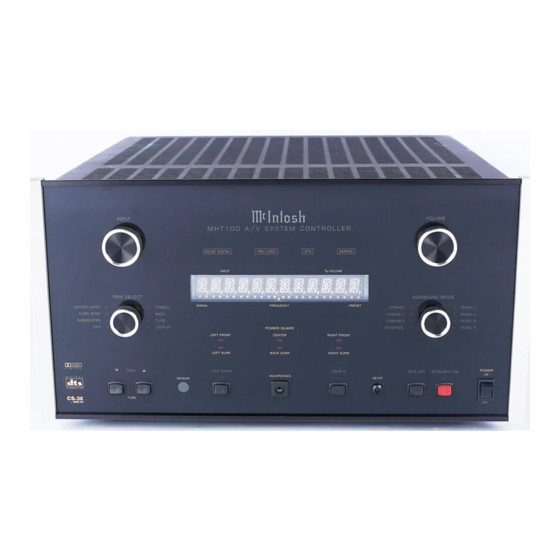
Owner's Manual
MHT100 A/V System Controller
Manufactured under license from Dolby Laboratories, "Dolby", "Pro Logic" and the double-D symbol are
MHT100
registered trademark of Dolby Laboratories, Inc.
and
symbol are trademarks of SRS Labs, Inc.
Technology is incorported under license from SRS labs, Inc. "DTS", "Digital Surround", and "Co-
herent Acoustics" are registered trademark of DTS Technology, LLC. and manufactured under license from
DTS Technology LLC.
McIntosh Laboratory, Inc.
2 Chambers Street
Binghamton, New York 13903-2699
Phone: 607-723-3512
FAX: 607-724-0549
Advertisement
Chapters
Table of Contents

Related Manuals for McIntosh MHT100

Summary of Contents for McIntosh MHT100
- Page 1 Owner’s Manual MHT100 A/V System Controller Manufactured under license from Dolby Laboratories, “Dolby”, “Pro Logic” and the double-D symbol are MHT100 registered trademark of Dolby Laboratories, Inc. symbol are trademarks of SRS Labs, Inc. Technology is incorported under license from SRS labs, Inc. “DTS”, “Digital Surround”, and “Co- herent Acoustics”...
-
Page 2: Safety Instructions
The lightning flash with arrowhead, The exclamation point within an equi- within an equilateral triangle, is intended lateral triangle is intended to alert the to alert the user to the presence of user to the presence of important uninsulated “dangerous voltage” within operating and maintenance (servic- the product’s enclosure that may be of ing) instructions in the literature ac-... - Page 3 A. Use No. 10 AWG (5.3 mm ) copper No. 8 AWG McIntosh or have the same characteristics as the origi- (8.4 mm ) aluminum, No. 17 AWG (1.0 mm ) cop- nal part.
-
Page 4: Table Of Contents
Customer Service How to Adjust for Loudspeaker Time Delay ....28 If it is determined that your McIntosh product is in need of How to Adjust for Loudspeaker Levels ......29 repair, you can return it to your dealer. You can also return How to Adjust the Subwoofer ......... -
Page 5: General Notes
Zones A and B. 1. When the MHT100 A/V System Controller is sold in North 13. When a McIntosh WK-2 Keypad or a R649 Sensor is to be America, the TM1 AM/FM Tuner Module for Radio Station connected to the McIntosh MHT100 A/V Control Center Reception is already installed. -
Page 6: Connector Information
Connector Information Keypad Terminal Connector Data and IR Port Connectors To use a WK-3 or WK-4 keypad with the MHT100, con- The MHT100’s Data Port Output provides Remote Control nect the shield and four leads of a shielded 4 conductor... -
Page 7: Introduction
MHT100 A/V System Controller A Precision Tracking Volume Control adjusts all eight as the heart of your Home Theater System. The MHT100 channels with tracking accuracy better than 0.5dB. Digital provides superior eight channel reproduction, Dolby Digi-... -
Page 8: Dimensions
Dimensions Dimensions The following dimensions can assist in determining the best location for your MHT100. There is additional infor- mation on the next page pertaining to installing the MHT100 into cabinets. " 45.09cm Front View of the MHT100 " "... -
Page 9: Installation
Installation Installation The MHT100 can be placed upright on a table or shelf, that airflow is not obstructed. Allow 21 inches (53.34cm) standing on its four feet. It also can be custom installed in a depth behind the front panel. Allow 1 inch (2.54cm) in piece of furniture or cabinet of your choice. -
Page 10: Rear Panel Switch, Loudspeaker And Control Connections
POWER CONTROL A and B send a turn Connections for Zone B Loudspeakers, On/Off signal to a McIntosh Power Ampli- Left and Right fier for both Areas. The ACC POWER CONTROL sends a turn On/Off signal to McIntosh Source Components. -
Page 11: Rear Panel Audio And Digital Connections
ZONE A PREAMP OUTPUTs ceive a digital audio signal from the provide all eight audio channel Optical Output of a component signals to the MHT100 Power Amplifier Inputs via the Exter- nal McIntosh Plug In Jumpers. AUDIO INPUTS for analog audio signals... -
Page 12: Rear Panel Video Connections
VIDEO INPUTS are for both S-Video and Composite Video Signals from a AUX, CD, SAT, TV, DVD,VCR1 or VCR2 components Note: If the MHT100 A/V System Controller has the TM1 AM/FM Tuner Module installed, proceed to page 52 for Rear Panel COMPONENT INPUTS receive Antenna Connection Information. -
Page 13: How To Connect Data And Power Control
How to Connect for Data and Power Control How to Connect for Data and Power Control 1. Connect a Data Control Cable from the MHT100 DVD Powered Subwoofer Power Control In Jack. Data Port to the McIntosh MVP841 DVD Player Data 7. -
Page 14: Loudspeakers
Note: The use of Banana Plugs is for use in the United 1. Prepare the Loudspeaker Hookup Cables that attach to States and Canada only. the MHT100 A/V System Controller by choosing one of 2. Connect the Loudspeaker Hookup Cables from the the methods below:... - Page 15 How to Connect the Loudspeakers Center Front Loudspeaker Right Front Left Front Loudspeaker Loudspeaker Right Surround Left Surround Loudspeaker Loudspeaker Back Surround Loudspeaker...
-
Page 16: Audio And Digital Components
Signal Inputs. It is important to connect the Analog Outputs Satellite Receiver. along with the Digital Audio Signal Output from source 4. Connect a cable from the MHT100 Audio SAT INPUTs components connected to the MHT100. This will assure to the Audio Outputs of the Satellite Receiver. -
Page 17: Video Components
Composite, S-Video and Component Video Signals can be 5. Connect video cables from the MHT100 VCR1 IN- connected to and selected by the MHT100. The built-in On PUTS to the VCR Video Outputs. Screen Operating Status and Setup Information is available 6. -
Page 18: Zone B
How to Connect for Zone B How to Connect for Zone B The MHT100 is a Dual Zone A/V System Controller. For Zone B activation a McIntosh Sensor or Keypad together with a pair of Loudspeakers are required. To provide the best video quality for Zone B, it is important to use a high quality cable and keep the cable length as short as possible. -
Page 19: Front Panel Features Controls, Sensor And Headphone Jack
Zone B B Video Outputs, and available for VCR Outputs IR (Infra Red) Sensor ac- cepts IR signals directly from the MHT100 Remote Control Low Impedance Dynamic Headphones can be connected for two channel listening and the Zone A Loudspeakers are... -
Page 20: Push-Buttons And Switch
Front Panel Push-buttons and Switch Tunes Up or Down the AM Switches Zone A On/Off or FM Broadcast Band or and Zone B On/Off only Presets when the TM1 if Zone A is already On Tuner Module is installed and allows up or down ad- justment for each trim func- tion Activates control of Zone B,... -
Page 21: Displays
Indicates when the Indicates when the Power Indicates when the Input Source selected Guard Circuit has been acti- MHT100 is in is processing a Digital vated for the Left Front, Center, Standby/On Mode Signal Right Front, Left Surround,... -
Page 22: Remote Control Push-Buttons
Remote Control Push-Buttons Turns AC Power ON or OFF to certain McIntosh Components when connected via the Data Port Press to Power the MHT100 ON or OFF Selects Functions for McIn- tosh Home Controller Selects one of the eight Audio/Video Sources... -
Page 23: Operate By Remote Control
Note: The above Tuner Function requires either the TM1 Tuner Module installed in the MHT100 or an external can be controlled by the MHT100 with the addition of a McIntosh Tuner connected to the MHT100. McIntosh Remote Control Translator (RCT) and/or op- tional UR12 Touch Screen Remote Control. -
Page 24: How To Operate The Setup Mode
How to Operate the Setup Mode Your McIntosh MHT100 has been factory configured for 2. Press and hold the MHT100 Front Panel SETUP Push- default operating settings that will allow immediate enjoy- button approximately ment of superb video and high fidelity audio without the three seconds to enter the need for further adjustments. -
Page 25: Default Settings
SETUP Default Settings The following listings indicate the factory default settings. Refer to the listed page number for instructions on how to change a default setting. MAIN SYSTEM SETUP Speaker Size: Speaker Type Size or ON/OFF Refer to Page 1. SPEAKER SIZE Front ...... -
Page 26: How To Reset The Mht100
1 ......SAT ......34 How to Reset the MHT100 2 ......DVD ......34 If it should become necessary to reset the MHT100 to the Default Settings, follow the procedure below: Video Power Control: Notes: 1. First, if you are experiencing difficulties in operating... -
Page 27: How To Adjust For Loudspeaker Size
5. Select EXIT from the MAIN SYSTEM SETUP Menu. If you are satisfied with the changes that you may Loudspeaker Size have made, select YES to save those changes or NO not to save them. The MHT100 will then return to Loudspeaker Default Setting New Setting normal operation. -
Page 28: How To Adjust For Loudspeaker Time Delay
YES to save those changes or NO not to to each of the Loudspeakers. Refer to the table below. save them. The MHT100 will then return to normal op- Note: A distance measurement that contains fractions of a foot, should be rounded up or down to the nearest eration. -
Page 29: How To Adjust For Loudspeaker Levels
Level adjustments are made 2. BACK SURROUND 0.0dB 3. LEFT SURROUND 0.0dB in small steps (1/2 dB) by using the MHT100 Remote Con- 2. SUBWOOFER 0.0dB trol LEVEL Push-button. The level can be adjusted over a EXIT plus or minus 15dB range. - Page 30 If you are satisfied with the changes that you may have made, select YES to save those changes or NO not to MENU: SPEAKER LEVEL save them. The MHT100 will then return to normal op- eration. Refer to figure 13 on page 25. 1. NOISE LEFT 2.
-
Page 31: Subwoofer
3. CENTER 0.0dB you may have made, select YES to save those 2. RIGHT FRONT 0.0dB changes or NO not to save them. The MHT100 3. RIGHT SURROUND 0.0dB will then return to normal operation. Refer to fig- 2. BACK SURROUND 0.0dB... -
Page 32: How To Adjust The Subwoofer
5. Select EXIT from the MAIN SYSTEM SETUP Menu. If you are satisfied with the changes that you may have made, select YES to save those changes or NO not to save them. The MHT100 will then return to normal op-... -
Page 33: Dd Lfe Level
Figure 23 made, select YES to save those changes or NO not to select DD LFE LEVEL from the On-Screen Menu, fol- save them. The MHT100 will then return to normal op- lowed by pressing the Left directional push-button to eration. -
Page 34: How To Change Source Settings
How to change Source Settings The MHT100 Setup Mode Source Settings allow any of the seven Analog Audio/Video Inputs, six Digital Audio Inputs and two Component Video Inputs to either be reassigned MENU: SOURCE SETTINGS and/or retitled from the default settings. For example, AUX can be retitled as DVD2. -
Page 35: Aux
Control when switching between different Program Digital Input Sources. A volume trim feature on the MHT100 allows you There are three Optical Digital Inputs and three Coaxial to adjust or trim the levels of the various inputs so that they Digital Inputs available for assignment with any of the have the same relative volume. - Page 36 Monitor/TV screen. 5. COMPONENT INPUT 1 15. Select EXIT from the MAIN SYSTEM SETUP Menu, select YES to save the changes and the MHT100 will then return to normal operation. EXIT 16. Compare the new AUX Input Volume Level to the Tuner Volume Level.
-
Page 37: How To Assign The Video Power Control
Turn-On Signal whenever Zones A or B of followed by pressing the Left or Right directional the MHT100 is On) or Video Power Control Off. Refer push-buttons to select the desired amount of time the to figure 27. Turn-On Signal will be present. Select EXIT on the... -
Page 38: How To Change System Setup
SETUP, con’t How to change System Setup The MHT100 is marketed all over the world. The SYS- TEM SETUP allows for selection of the proper Video For- mat Standard for the On-Screen Displays. If the AM/FM MENU: SYSTEM SETUP Tuner Module is installed there are also selections to match the Tuner Functioning with the Radio Broadcasts in your 1. -
Page 39: How To Operate The Mht100
“How to Make a the STANDBY/ON Push-button illuminates, to indicate the Recording” on page 42 MHT100 is in Standby Mode. Switch On the MHT100 by and “How to Operate pressing the STANDBY/ON Push-button. The title Zone B” on page 47 for MHT100 will appear on the Front Panel Alphanumeric additional information. - Page 40 Power Push-button on a Keypad or Remote information. Control. If you desire to switch Off both Zones of the McIntosh MHT100 A/V System Controller and connected Late Night accessory source components, press the SYS OFF Push- The LATE NIGHT Push-button turns a volume compres- button on the Front Panel.
- Page 41 How to Operate the MHT100, con’t On-Screen Display The MHT100 has a Dynamic On-Screen Display making it easy to know the operating status without refering to the Front Panel. Press the current Source Selected Input Push-button on the McIntosh Remote Control and the On-Screen Display will appear on the TV/Monitor.
-
Page 42: How To Make A Recording
INPUT Selector Switch to select the recorder used. ten (monitor) to the recorded signal off the tape, a fraction Note: The MHT100 RECORD OUTPUTS are not affected by the VOLUME control. To listen to a different program of a second later, during recording when a source while recording, turn the INPUT Selector Switch three head tape recorder is used. -
Page 43: How To Operate The Trim Mode
How to Operate the MHT100, con’t How to Operate the Trim Mode The MHT100 TRIM SELECT Switch together with the Material in order to hear any TRIM LEVEL Control provide the means for adjusting changes in the five different audio functions and the Front Panel Alphanu- Subwoofer meric Display Brightness. - Page 44 Bass and Treble Display Brightness The MHT100 allows for changing the tonal response for The MHT100 Trim feature allows adjustments to the any of the eight sources via the BASS and TREBLE TRIM brightness of the Front Panel Alphanumeric Display to the Adjustments.
-
Page 45: How To Operate The Surround Mode
How to Operate the MHT100, con’t How to Operate the Surround Mode The MHT100 provides eight different Surround Modes. The Front Panel Al- phanumeric Display indicates the Sur- Figure 50 round Mode se- is sent to the Left and Right lected. -
Page 46: How To Operate Zone B
How to Operate Zone B Cinema 1 The MHT100 includes the capability of being able to oper- This provides decoding of Dolby Pro Logic Analog or ate and control two audio/video zones, independently of Digital Signals and decoding of Dolby Digital or DTS Sig- each other. - Page 47 Refer to figures 60, 61 and 62. Note: If Zone A is On, Zone B Input may be changed from the MHT100 Front Panel by first pressing the ZONE B Push-button and then rotating the INPUT Selector Control until the desired source is selected.
-
Page 48: Preamplifier And Procesors Specifications
Preamplifier and Processor Specifications Preamplifier and Processor Specifications Frequency Response Tone Controls STEREO Left and Right Loudspeakers: ±12dB from the flat setting +0 -0.5dB from 20Hz-20,000Hz If any of the Channels have the Loudspeaker Setting of MUSIC 1-4 Left, Center, Right Loudspeakers: Small, the subwoofer has a electronic low pass filter with +0 -0.5dB from 20Hz-20,000Hz a corner frequency of 80Hz and a 24dB per Octave... -
Page 49: Power Amplifier And General Specifications
230 Volts, 50/60Hz at 3.5 Amps Rated Power Band 240 Volts, 50/60Hz at 3.5 Amps 20Hz to 20,000Hz NOTE: Refer to the rear panel of the MHT100 for the correct voltage. Total Harmonic Distortion Maximum Total Harmonic Distortion at any power... - Page 50 TM1 AM/FM Tuner Module Introduction Cables for installing the McIntosh TM1 When the MHT100 A/V System Controller is sold outside Cable for connecting the AM/FM Tuner Module RAA1 to the MHT100 of North America, the optional McIntosh TM1 AM/FM into the MHT100 Tuner Module can be added for Radio Broadcast Recep- tion.
-
Page 51: Mht100 Rear Panel And Raa1 Top Panel Antenna Connections
MHT100 Rear Panel and RAA1 Top Panel Antenna Connections RAA1 Remote Antenna can be adjusted to a position for optimum reception of your fa- vorite AM stations Connects with supplied cable to the MHT100 AM ANT (An- tenna) connector allows a McIntosh... -
Page 52: How To Connect Antenna Components
MHT100 and the RAA1 use a 2 conductor shielded cable. Refer to page 6 for additional connection information. 2. Connect a 75 ohm coax cable from an FM antenna or cable system to the MHT100, 75 ohm FM ANT con- nector. FM Antenna... - Page 53 TUNER SETUP How to Assign the Tuner Presets The MHT100 Setup Mode Tuner Presets allow for the pre- setting into memory 9 FM and 9 AM Radio Stations for fast recall at any time. In addition, any preset can have a unique name assigned to it.
- Page 54 Right rectional push-buttons to select Yes or No. If No is se- lected the MHT100 will skip that Preset, even though it has been entered. Refer to figure 67. Select EXIT on the menu and the MAIN SYSTEM SETUP Menu will reappear on the Monitor/TV screen.
-
Page 55: How To Operate The Tuner
How to Operate the Tuner How to Operate the Tuner The McIntosh MHT100 TM1 AM/FM Tuner Module in- up or down the broadcast corporates an advanced design AM/FM Tuner with many band. When a station is se- desirable performance features to enhance your enjoyment lected, the Front Panel Al- of radio broadcasts. -
Page 56: How To Optimize Am Reception
How to Optimize AM Reception How to Optimize AM Reception The McIntosh RAA1 Remote AM Antenna is designed to tool, adjust the 600kHz Transformer L1 for maximum provide the best in AM Reception especially if the tuner or signal strength. Refer to figure 71. -
Page 57: Am Specifications
TM1 FM and AM Specifications FM Tuner Specifications AM Tuner Specifications Useable Sensitivity Sensitivity 14dBF which is 1.4uV across 75 ohms 20uV External Antenna Input 50dB Quieting Sensitivity Signal To Noise Ratio Mono: 19dBF which is 2.4uV across 75 ohms 48dB at 30% modulation Stereo: 35dBF which is 15uV across 75 ohms 58dB at 100% modulation... - Page 58 Notes...
-
Page 59: Packing Instruction
Slit scored wrap carton or any of the interior part(s) are needed, please call 034196 Shipping skid or write Customer Service Department of McIntosh Labo- ratory. Please see the Part List for the correct part numbers. 017218 Plastic foot 100159 #10-32 x 3/4”... - Page 60 McIntosh Laboratory, Inc. 2 Chambers Street Binghamton, NY 13903 McIntosh Part No. 040743...