
Related Manuals for American Audio 14MXR


Summary of Contents for American Audio 14MXR
-
Page 1: User Guide
14MXR User Guide and Reference Manual 6122 S. Eastern Ave. Los Angeles Ca. 90040 www.AmericanAudio.us 10/12... -
Page 2: Table Of Contents
• 2 0 On-Board Midi Control Buttons • Gain, Bass, and Treble for Mics 1 & 2 (Mapable) • USB Connection • D igital BPM Display • High level headphone output • B uilt-In DSP D-Core™ Sound Card • Cue mixing • Controller Mode: USB Output Streams are • Split cue for headphones routed through master and headphone out- • Turntable ground connectors located on the rear puts panel American Audio - www.americanaudio.us - 14MXR Instruction Manual Page 2 © ®... -
Page 3: Electrical Precautions
To prevent electromagnetic inter- ference with electrical appliances such as radios and televisions, use shielded cables and connectors for connections. American Audio - www.americanaudio.us - 14MXR Instruction Manual Page 3 © ®... -
Page 4: Important Safety Instructions
(NEC SECTION 810-21) used for a long period of time. EQUIPMENT GROUND CLAMPS POWER SERVICE GROUNDING ELECTRODE SYSTEM Fig. A (NEC ART 250, PART H) NEC — NATIONAL ELECTRICAL CODE American Audio - www.americanaudio.us - 14MXR Instruction Manual Page 4 © ®... -
Page 5: Safety Precautions
7. Never disassemble or modify your unit in 18. Always have the front gain controls set to any way, doing so will void your manufactures their lowest level during initial power-up to pre- warranty. vent speaker damage. 8. Never plug this mixer in to a dimmer pack. American Audio - www.americanaudio.us - 14MXR Instruction Manual Page 5 © ®... -
Page 6: Introduction
Operating Determinations: • When installing this mixer, please make sure that the device is not exposed or will not be exposed to extreme heat, moisture or dust! • Do not operate the mixer in extremely hot (more than 30°/100°F) or extremely cold (less than 5°C/40°F) surroundings. • Keep the unit out of direct sunlight and away from heaters. • Operate the mixer only after becoming familiar with its functions. Do not permit operation by persons not qualified for operating the mixer. Most damages are the result of unprofessional operation! • Do not attempt to operate this mixer if the power cord has been frayed or damaged. • Disconnect from main power before making any type of connection. • Do not attempt to operate this mixer, if it becomes damaged in any way. • Never operate this mixer when it’s covers are removed. • To reduce the risk of electrical shock or fire, do not expose this mixer to rain or moisture. • This mixer is intended for indoor use only, use of this product outdoors voids all warranties. • During long periods of non-use, disconnect the mixer’s main power. American Audio - www.americanaudio.us - 14MXR Instruction Manual Page 6 © ®... -
Page 7: Unpacking
MAIN MIC - The main mic connector uses a combo plug that allows you to connect either a 1/4” unbalanced jack or by a standard 3-pin XLR balanced connector. The main mic also has an indepen- dent volume control. When feedback occurs when using the mic, try lowering the level this may reduce the feedback. Always leave the mic level to it’s minimum level when not in use. Note: We recommend that you use a 500-600ohm microphone for the best sound quality. CHANNEL LINE LEVEL SELECTOR SWITCHES - This switch is used to change the selected input from phono to line and vice versa. The switch selectors are on the rear panel. American Audio - www.americanaudio.us - 14MXR Instruction Manual Page 7 © ®... -
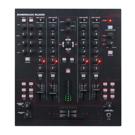
Page 8: Front Panel
14MXR CONTROLS AND FUNCTIONS FRONT PANEL American Audio - www.americanaudio.us - 14MXR Instruction Manual Page 8 © ®... - Page 9 LEVEL KNOB (6). Be sure the CUE MIXING KNOB (7) is set to the “CUE” position to hear a selected channel source. CHANNEL VOLUME FADER - These faders are used to control the output signal of any source assigned to its particular channel. However, master volume is controlled by the MASTER VOLUME CONTROL (3). 2. BOOTH LEVEL - This knob is used to adjusts the booth volume output level. Turn the knob in a clockwise direction to increase the monitor volume. 3. MASTER VOLUME CONTROL - This knob is used to control the master output level (main volume). To avoid distorted output try to maintain an average output signal level no greater than +4 dB. To American Audio - www.americanaudio.us - 14MXR Instruction Manual Page 9 © ®...
- Page 10 7 & 8. 6. CUE LEVEL VOLUME CONTROL - This knob is used to adjusts the headphone volume output level. Turn the knob in a clockwise direction to increase the headphone volume. 7. CUE MIXING CONTROL - This functions allows you to monitor the Cue level as well as the Program (main output) level in your headphones. A channels Cue Level may only be monitored if the American Audio - www.americanaudio.us - 14MXR Instruction Manual Page 10 © ®...
- Page 11 LEVEL VOLUME (6) is set to minimum before you put the headphones on. 13. FEATHER FADER PLUS CROSSFADER - This fader is used to blend the output signals of chan- nels one and two together. When the fader is in the full left position (channel 1), the output signal of channel one will be controlled by the master volume level. The same fundamentals will apply for chan- nel two. Sliding the fader from one position to another will vary the output signals of channels one and two respectively. When the crossfader is set in the center position, the output signals of both the channels one and channels two will be even. 14. CROSSFADER CURVE ADJUSTMENT - This rotary knob is used to change the way the cross- fader will operate. The crossfader can operate in different modes, “NORMAL CURVE”, “QUICK CURVE” or any variation of the two. (Quick Curve is usually used for scratching). American Audio - www.americanaudio.us - 14MXR Instruction Manual Page 11 © ®...
- Page 12 MICROPHONE 1 & 2 MIDRANGE CONTROL - This knob is used to adjust the midrange levels of the Microphone with a maximum signal gain of 12dB or maximum signal decrease of -12dB. Turning the knob in a counter-clockwise direction will decrease the amount of treble applied to the micro- phone signal, turning the knob in a clockwise direction will increase the amount of treble applied to microphone signal. MICROPHONE 1 & 2 BASS CONTROL - This knob is used to adjust the low frequency levels of the microphone with a maximum signal gain of 12dB or maximum signal decrease of -12dB. Turning the knob in a counter-clockwise direction will decrease the amount of bass applied to the microphone signal, turning the knob in a clockwise direction will increase the amount of bass applied to micro- phone signal. TALKOVER CONTROL - This function decreases all signal output except the microphone signal. The amount of decrease is preset to -14dB and is not user selectable. American Audio - www.americanaudio.us - 14MXR Instruction Manual Page 12 © ®...
-
Page 13: Rear Panel
20. CHANNEL 2: INPUTS - The type of input must directly reflect the selected mode of the CHAN- NEL LINE LEVEL SELECTOR SWITCH (21). CD players, Tape Decks and other line level instruments may be connected to these jacks. The red colored RCA jack represents the right channel input and the white represents the left channel input. Input volume will be controlled by channel two fader. The channel SOURCE SELECTOR SWITCH (1) must be in the “Analog” position, to monitor any source connected to these jacks. Turntables equipped with MM pickup cartridge (All DJ turntable use MM pick-up cartridges) may be connected to these jacks as long as the CHANNEL LINE LEVEL SELEC- American Audio - www.americanaudio.us - 14MXR Instruction Manual Page 13 © ®... - Page 14 26. BALANCED XLR MASTER OUTPUT JACKS - The Master Output includes a pair of XLR Balanced jacks as well as a pair of RCA UNBALANCED JACKS (24). The 3-pin XLR jacks send a high current balanced output signal. These jacks should be used when you will be driving an amp or other audio equipment with a balanced input, or whenever you will be running a signal line greater than 15 feet. Always, use these jacks whenever possible. 27. USB PORT - Connect to your PC for MIDI interface and USB interface (audio in and outs). American Audio - www.americanaudio.us - 14MXR Instruction Manual Page 14 © ®...
- Page 15 28. MAIN POWER SWITCH - This is the main power ON/OFF button. Before main power is applied, be sure you have made all connections to the mixer. Also be sure your amplifier(s) is(are) tuned off. Remember to avoid damaging pops to the speakers, the mixer is turned on first and turned off last. 29. AC CONNECTION - This connector is used to supply main power to the unit via the included detachable power cord. The power connection uses an I.E.C. type connector, use only the supplied, polarized AC power cord. Use only a power cord that matches this type of connection. Be sure to only connect this unit to a power outlet that matches the printed power label on the unit. Never use a power cord when the ground prong has been removed or broken off. The ground prong is used to reduce the risk of electrical shock in case of an electrical short. This cord is designed to fit in one direction only. Do not attempt to force a cord if it does not fit, be sure the cord is being inserted properly. FUSE HOLDER – This housing stores the 10 amp GMA protective fuse. Always replace with the exact same type fuse, unless otherwise instructed, by an authorized American Audio service tech- ® nician. Replacing with any other type of fuse than that of the recommended fuse will void your unit warranty. American Audio - www.americanaudio.us - 14MXR Instruction Manual Page 15 © ®...
-
Page 16: Midi Table
Button / LED 64 / 64 00H = released, 7FH = pressed Note on 90H (91H) Left Buttons American Audio - www.americanaudio.us - 14MXR Instruction Manual Page 16 © ® CUE Left Button / LED 12 / 12 00H = released, 7FH = pressed Note on 90H (91H) PLAY/PAUSE >|| Left... - Page 17 00H = released, 7FH = pressed Note on 90H (91H) SYNC Right Button / LED 55 / 55 00H = released, 7FH = pressed Note on 90H (91H) American Audio - www.americanaudio.us - 14MXR Instruction Manual Page 17 © ®...
-
Page 18: Typical Mixer Set-Up
C A S S E T T E D E C K T U R N TA B L E T U R N TA B L E This image details a typical DJ Set Up consisting of a microphone, turntables, CD players, and a tape deck. Note: Turntables can only be connected to the PHONO LEVEL RCA JACKS. Be sure the LINE LEVEL SELECTOR SWITCHES are in the "PHONO" position when using turntables. American Audio - www.americanaudio.us - 14MXR Instruction Manual Page 18 © ®... - Page 19 14MXR TYPICAL MIXER SET-UP Balanced XLR male to XLR female Cables American Audio V4001™ Speaker Cables Typical Balanced Output Set-up This image details a typical stereo output layout. Note the use of the Balanced XLR Jacks on both the mixer and the amplifier. Always use the balanced output jacks whenever possible. The balanced output jacks should always be used for cable runs in excess of 15 feet. Using the balanced jacks will ensure a clean signal through out the entire audio system. American Audio - www.americanaudio.us - 14MXR Instruction Manual Page 19 © ®...
-
Page 20: Cleaning
4. Always be sure to dry all parts completely before plugging the mixer in. Cleaning frequency depends on the environment in which the mixer operates (i.e. smoke, fog residue, dust, dew). 14MXR CROSS FADER REPLACEMENT The crossfader is “Hot Swapable” which means it may be replaced at any time, even when power is applied. Only replace with American Audio Part Feather Fader Plus. Replacing with any other model fader may seriously damage your mixer. Replacing the Crossfader: 1. Disconnect the mixers main power supply 2. Using a number two Phillips screw driver, unscrew the each of the stainless steel retain screws that hold the crossfader in place. 3. Gently remove the crossfader from its seated position. You may need to wiggle the crossfader slightly to remove it. 4. After removing the crossfader, disconnect the ribbon cable that attaches the crossfader to the PC board. Grasp the crossfader by its base and pull the ribbon cable by its connector not the actual cables. The connector is designed to only fit one way, so don’t worry about the connec tors orientation. 5. Connect the new crossfader to the ribbon cable and replace in reverse order. American Audio - www.americanaudio.us - 14MXR Instruction Manual Page 20 © ®... -
Page 21: Troubleshooting
Trouble Shooting: Listed below are common problems you may encounter, and solutions. There is no power to the unit: Be sure you have connected the power cord to a correct wall outlet. There is little or no sound: 1. Check the input selector switch. Make sure it is set to the device that is currently playing. 2. Check to see if the connection cables are connected properly. The sound is distorted: 1. Make sure that the Gain level control is not set to high. Crossfader is not working: Check and see if any channels have been assigned to the crossfader. American Audio - www.americanaudio.us - 14MXR Instruction Manual Page 21 © ®... -
Page 22: Warranty
® chantability or fitness, are limited in duration to the warranty period set forth above. And no warran- ties, whether expressed or implied, including warranties of merchantability or fitness, shall apply to this product after said period has expired. The consumer’s and or Dealer’s sole remedy shall be such repair or replacement as is expressly provided above; and under no circumstances shall American Audio be liable for any loss or damage, direct or consequential, arising out of the use of, or inability ® to use, this product. G. This warranty is the only written warranty applicable to American Audio Products and supersedes ® all prior warranties and written descriptions of warranty terms and conditions heretofore published. American Audio - www.americanaudio.us - 14MXR Instruction Manual Page 22 © ®... -
Page 23: Specifications
0.1% MIC: 0.1% CROSS TALK: (Maximum Gain, EQ Flat) LINE, AUX, PHONO: -55dB Channel Equalizer: (Maximum Gain, Master Unbal Out) BASS: -15dB ~ +11dB MID: -13dB ~ +11dB TREBLE: -24dB ~ +12dB Microphone Equalizer: (Maximum Gain, Master Unbal Out) BASS: -15dB ~ +11dB MID: -13dB ~ +11dB TREBLE: -24dB ~ +12dB American Audio - www.americanaudio.us - 14MXR Instruction Manual Page 23 © ®... - Page 24 ©American Audio® World Headquarters: 6122 S. Eastern Ave. Los Angeles, CA 90040 USA Tel: 323-582-3322 Fax: 323-582-3311 Web: www.AmericanAudio.us E-mail: info@americanaudio.us American DJ Europe Junostraat 2 6468 EW Kerkrade Netherlands service@adjgroup.eu / www.americandj.eu Tel: +31 45 546 85 00 / Fax: +31 45 546 85 99...