Table of Contents
Advertisement
Quick Links
Dystrybutor w Polsce:
AUTOMATECH Sp.z o.o.
Programmable Display
GT10/GT30
Technical Manual
Includes installation guide for GTWIN screen
creation software.
Applicable Models
GT10 (Ver. 1/Ver. 2)
GT30
www.automatech.pl
Tel.: +48 22 723 0606
e-mail: biuro.warszawa@automatech.pl
Fax: +48 22 723 0662
is a global brand name of Matsushita Electric Works.
Advertisement
Table of Contents

Related Manuals for NAiS GT10

Summary of Contents for NAiS GT10
- Page 1 Tel.: +48 22 723 0606 Programmable Display GT10/GT30 Technical Manual Includes installation guide for GTWIN screen creation software. Applicable Models GT10 (Ver. 1/Ver. 2) GT30 e-mail: biuro.warszawa@automatech.pl Fax: +48 22 723 0662 is a global brand name of Matsushita Electric Works.
- Page 2 SAFETY PRECAUTIONS [ALWAYS OBSERVE THESE PRECAUTIONS] Before installing, operating, servicing or inspecting this product, please make sure you have read this manual and the explanations of how procedures are carried out, and make sure the product is used correctly. This manual uses two safety standard levels: “WARNING” and “CAUTION”. WARNING Erroneous handling of an item marked with this label can cause fatal or critical injury to the user.
- Page 3 This chapter explains how to connect the GT series to the PLC and the FP series by Matsushita, and how to set up communications between the units. Chapter 5. GT10 Configuration Settings This chapter describes the configuration settings for the GT10, and how they should be entered. Chapter 6. GT30 Configuration Settings This chapter describes the configuration settings for the GT30, and how they should be entered.
-
Page 4: Table Of Contents
..........GT10 Names and Functions of Parts 1.2.1... - Page 5 Wiring Method 2.3.2 Precautions Concerning Wiring Chapter 3 Setup Setup Procedure for the GT10 Setting the Basic Communication Area, GT10 and PLC 3.2.1 What is the Basic Communication Area? 3.2.2 GT10 Basic Communication Area Map Setup Procedure for the GT30 Setting the Basic Communication Area, GT30 and PLC 3.4.1...
- Page 6 SYSMAC C Series, a Series, CV Series, and CS1 Series Chapter 5 GT10 Configuration Settings GT10 Configuration Settings 5.1.1 Two Types of GT10 Configuration Settings Entering Configuration Settings with GTWIN 5.2.1 Opening the GT Configuration Settings 5.2.2 GT Configuration Settings: “Basic Setup”...
- Page 7 Replacing the Waterproof Packing Replacing the Backlight (GT30 Only) Chapter 9 Troubleshooting What to Do If Something Unusual Occurs (GT10) What to Do If Something Unusual Occurs (GT30) Error Codes and How to Handle Them 9.3.1 GT Series Error Codes 9.3.2...
- Page 8 GT10/GT30 GT10 Screen Messages GT30 Screen Messages Part II Screen Creation Tool Terminal GTWIN Usage Environment and GT Main Unit Models that are Supported Important Note About Saving Screen Data Files Chapter 10 Preparing GTWIN 10.1 Installing GTWIN ..........
- Page 9 GT10/GT30 Table of Contents viii...
-
Page 10: Part Igt10, Gt30 Main Unit
Part I GT10, GT30 Main Unit... -
Page 11: Before Using The Gt10/Gt30
GT10/GT30 Before Using the GT10/GT30 This section describes items that should be confirmed and precautions that should be observed before the GT10/GT30 is used. Make sure you read this section before using the GT10/GT30. -
Page 12: Gt10/Gt30 Usage Procedures
GT10/GT30 GT10/GT30 Usage Procedures If you are using the GT10/GT30 for the first time, please follow the procedure outlined below. Procedure For Using the GT10/GT30 1. Confirm the items included with the product. Please confirm that all of the items have been included with the product you have purchased. - Page 13 GT10/GT30 GT10/GT30 Usage Procedures 7. Install the screen creation tool. page 149 Install the Terminal GTWIN screen creation tool in the personal computer. Follow the instructions on page 149 and subsequent pages to install the software. 8. Create the screen contents.
-
Page 14: Confirming The Package Contents
GT10/GT30 Confirming the Package Contents Check to make sure the necessary items have been included with the product you have purchased. Items Included with the GT10 (AIGT1000B) Main unit Set of attachment fittings Attachment fittings x 4 Attachment screws x 4... - Page 15 GT10/GT30 Items Included with the GT30 (AIGT3100B/AIGT3300B) Main unit STN monochrome liquid crystal display type: AIGT3100B STN color liquid crystal display type: AIGT3300B Set of attachment fittings Fittings x 2 Front panel protective sheet There is a front panel protective sheet, available as an optional product, attached to the front panel of the unit.
- Page 16 Read the “Software usage license agreement” carefully, and fill in the user card. Please return the user card to Matsushita. GT10/GT30 Technical Manual This is the manual you are currently reading. It contains instructions on installing and booting GTWIN. Please read it carefully before using your product.
- Page 17 GT10/GT30 Items Included With the PLC Connection Cable (AIGT8192 / AIP81842D) Cable One of the following two cables has been included with the product you have purchased. AIP81842D (2m) AIGT8192 (2m) Wiring diagram The package includes a diagram that shows the internal wiring of the cables pictured above.
-
Page 18: Gt Series System Configuration
Product No.: AIGT8192 Connecting to the TOOL port of the FP0 / FP2 / FP2SH / FP–M Terminal GTWIN English–language version Windows 95/98/2000/NT supported GTWIN CD–ROM GT10 Technical Manual included as accessory Product No.: AIGT8001V2 Main unit GT30 GT10 STN monochrome liquid... - Page 19 GT10/GT30 GT Series System Configuration CAUTION Connecting to the COM. port of the FP0 Because connecting the unit to the COM. port of the FPΣ/FP0 requires a loose–wire connection, this cable is not available. For more detailed information, please see “Connecting the FPΣ” on page 42 or “Connecting the FP0”...
-
Page 20: Products For The Gt Series
Front panel protective sheet for GT30 (for replacement). sheet Ten in set. * 1 sheet included with GT30 when shipped. Waterproof packing for GT10 (for replacement). Ten in set. * 1 piece included with GT10 when shipped. Waterproof Waterproof Waterproof packing for GT30 (for replacement). -
Page 21: Safety Precautions
GT10/GT30 Safety Precautions Before installing, operating, servicing or inspecting this product, please make sure you have read this manual and the installation instructions, and make sure the product is used correctly. This manual uses two safety standard levels: “WARNING” and “CAUTION”. - Page 22 GT10/GT30 Safety Precautions Special Items Maximum attention has been given to quality control of this product; however: (1) In order to prevent, as much as possible, unexpected situations not covered by these specifications, please consult us regarding your product’s specifications and demands, as well as this unit’s operating conditions and installation details.
- Page 23 GT10/GT30 Safety Precautions xxii...
-
Page 24: Chapter 1 Specifications
Chapter 1 Specifications... -
Page 25: Gt10/Gt30 Specifications
GT10/GT30 GT10/GT30 Specifications 1.1.1 General Specifications Item GT10 specifications Rated voltage 24 V DC Operating voltage range 21.6 to 26.4 V DC Power consumption 5 W max. 0°C to 40°C/32°F to 104°F Ambient temperature (25 V DC max. if installed horizontally) -
Page 26: Touch Key
Touch key operation Min. 10 Touch key life 1.1.5 Memory (1) Screen data and GTWIN Configuration Settings data Item GT10 specifications AIGT3100B Memory type F–ROM 384 kbytes Memory capacity 1.1.6 Memory (2) Clock data and PLC device storage data (24 words max.) -
Page 27: Interface
Conditions for communications with TOOL external devices port Protocol Connector GT10 specifications Conforms to RS232C Baud rate: 9600, 19200, 38400, 57600, 76800, 115200 bits/s Data bits: 7 or 8 bits Parity: None, Odd, Even Stop bits: 1 bit FP series supported/general–purpose RS232C supported Connector terminal base (5–pin) -
Page 28: Gt10 Names And Functions Of Parts
GT10/GT30 GT10 Names and Functions of Parts 1.2.1 GT10 (front) 1.2.2 GT10 (rear) 1.2.3 Names and Functions of Parts (1) Liquid crystal display panel / touch panel Various screens are displayed here. A touch panel is provided on the liquid crystal display panel, and switches can be operated and data entered simply by touching the panel. - Page 29 GTWIN has been installed, using a dedicated cable (AFC8513). (6) Operation mode setting switches With the GT10, screen data and configuration settings data are stored in an internal F–ROM, so no battery backup is needed. However, data such as clock data and the Hold PLC Device Data is stored in the internal SRAM, and is backed up by the internal secondary battery, which is charged when the power supply is turned on.
-
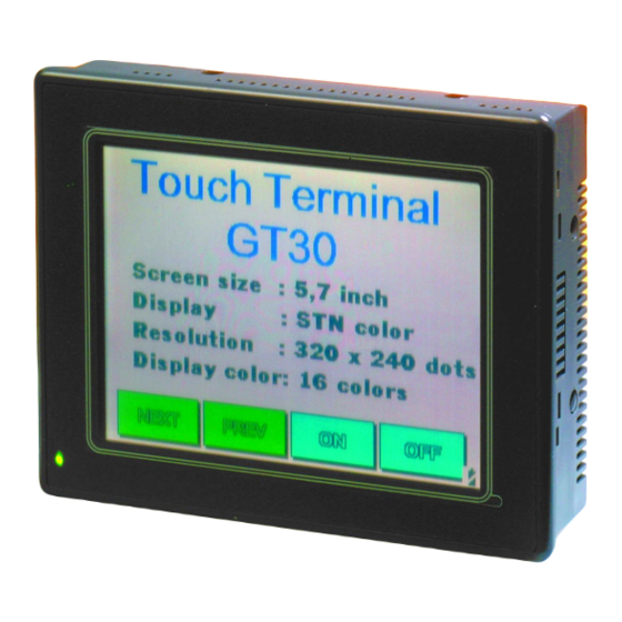
Page 30: Gt30 Names And Functions Of Parts
GT10/GT30 GT30 Names and Functions of Parts 1.3.1 GT30 (front) 1.3.2 GT30 (rear) 1.3.3 Names and Functions of Parts (1) Liquid crystal display panel / touch panel Various screens are displayed here. A touch panel is provided on the liquid crystal display panel, and switches can be operated and data entered simply by touching the panel. - Page 31 GT10/GT30 (3) Power supply terminal The operation power supply is connected here. (4) COM. port (PLC/external device connection port) A device such as a PLC, a higher–order computer, or a microcomputer board can be connected to this RS232C port. (One communication connector is provided as an accessory when the unit is shipped.)
-
Page 32: Internal Wiring Connections For Ports
GT10/GT30 Internal Wiring Connections for Ports 1.4.1 COM. Port 1.4.2 TOOL Port Pin No. Internal Wiring Connections for Ports When connecting the unit to the FP series, there is no need to wire both the RS and CS. Wiring and cables should be laid out in such a way that cables are not affected by external noise. -
Page 33: Power Supply Terminals
1.25 mm should be used for power cables. In keeping with the European EMC Directive (EMC Direc- tive 89/336/EEC), the GT10 conforms to European Stan- dards (EN50081–2:1993, EN50082–2:1995). As a condi- tion of compatible, a ferrite core should be installed when wiring to the terminal base (Seiwa Electric Mfg. -
Page 34: Dimensions
GT10/GT30 Dimensions Dimensions 1.5.1 GT10 Dimensions 32/1.26 4/0.16 144/5.67 2/0.08 (Display unit) 97/3.82 8.5/0.33 138.0/5.43 (Packing) 80/3.15 9.6/0.38 60/2.36 (Unit: mm/inch) -
Page 35: Gt10 Panel Cutout Dimensions
GT10/GT30 1.5.2 GT10 Panel Cutout Dimensions The panel cutout dimensions of the GT10 are as shown below. Applicable panel thickness: 1.0 to 6.0/0.002 to 0.236 1.5.3 GT30 Dimensions 177/6.97 0.04 /5.47 (Display unit) 4.4/0.17 158.2/6.23 (8/0.31) 150.2/5.91 Dimensions (Unit: mm/inch) 38.0/1.50... -
Page 36: Gt30 Panel Cutout Dimensions
GT10/GT30 Dimensions 1.5.4 GT30 Panel Cutout Dimensions The panel cutout dimensions of the GT30 are as shown below. 0.04 /5.93 150.5 Applicable panel thickness: 1.0 to 5.0/0.039 to 0.197 (Unit: mm/inch) - Page 37 GT10/GT30 Dimensions...
-
Page 38: Chapter 2 Installation And Wiring
Chapter 2 Installation and Wiring... -
Page 39: Installation
GT10/GT30 Installation 2.1.1 Installation Environment When installing and using the GT series, always make sure the following conditions are observed. Usage Conditions When installing the product, make sure it is used within the range of the general specifications. Do not use in the following environments: –... -
Page 40: Gt10 Installation Method
Other Precautions – Do not leave the GT10 connected to the TOOL port of the FP Programmer II. – Always operate the touch panel with your fingers. Excessive load (about 98 N/cm ) or impact (operating with tools, etc.) will cause damage. - Page 41 GT10/GT30 (2) Insert the fittings into the grooves provided in the GT10 main unit, and tighten the screws to secure the GT10 main unit to the installation panel. CAUTION Screw tightening torque The screw tightening torque should be 0.1 N m to 0.25 N m.
-
Page 42: Gt30 Installation Method
GT10/GT30 2.1.3 GT30 Installation Method Secure the GT30 to the installation panel using the two fittings and four screws provided with the unit. (1) Place the GT30 main unit in the installation panel. (2) Insert the fittings into the grooves provided in the GT30 main unit, and tighten the screws to secure the GT30 main unit to the installation panel. - Page 43 GT10/GT30 Installation clearance of 30 mm to 50 mm/1.18 inch to 1.97 inch around the GT30. This prevents cables from being damaged, and facilitates the installation work. Also, make sure that the slits in the main unit are never obstructed.
-
Page 44: Wiring The Power Supply
GT10/GT30 Wiring the Power Supply The power supply should be wired by securely connecting the terminal on the rear of the main unit to the terminal. Always use crimp terminals for wiring. +24 V F. E. (D–type ground) Use twisted wiring for the power supply In order to minimize influence from noise, the wiring for the power supply should be twisted. - Page 45 GT10/GT30 Keep the power supply wiring separate – Wiring to the GT series, PLC, and other power equipment should have separate wiring systems. Breaker Insulated DC power supply Power equipment GT series Wiring the Power Supply...
-
Page 46: Wiring The Com. Port
GT10/GT30 Wiring the COM. Port Accessory communication connector/applicable wiring The communication connector used for the COM. port (provided as an accessory with the main unit) has a screw–tightening type of terminal base. The wiring shown below should be used. Accessory communication connector The communication connector is made by Fenics Contact Co., Ltd. -
Page 47: Wiring Method
GT10/GT30 2.3.1 Wiring Method (1) Remove the sheath from the wire. 7 mm/0.28 inch (2) Insert the wire all the way into the terminal base, and tighten the screw in the clockwise direction to secure it. 2.3.2 Precautions Concerning Wiring The following precautions should be observed, to avoid broken or disconnected wires. -
Page 48: Chapter 3 Setup
Chapter 3 Setup... -
Page 49: Setup Procedure For The Gt10
Always confirm “Basic communication area to PLC” under “Basic Setup” This is an internal device area that comes already provided in the GT10 for the purpose of communicating with a PLC. If the factory settings are to be changed, the setup procedure must be carried out. - Page 50 GT10/GT30 3.1 Setup Procedure for the GT10 (3) Transfer the GT10 Configuration file from GTWIN. After connections have been completed, use the following procedure to transfer the GT10 Configuration file from GTWIN. Boot GTWIN, and select “Transfer” on the “File” menu.
- Page 51 GT10/GT30 When the menu operation as shown at the left page is carried out, the configuration file is sent to the GT10. During the transfer, a screen like that shown below is displayed. GTWIN (4) Setup is completed. If the transfer has been completed without any problems, the setup is completed.
-
Page 52: Setting The Basic Communication Area, Gt10 And Plc
Communication GT10 As shown in the illustration, communication is carried out on an ongoing basis between the GT10 and internal devices in the PLC. Internal PLC devices are divided into the following two devices: Basic communication area This area is for system control, such as screen switching settings. PLC devices belong to this area on a fixed basis, and communication is constantly being carried out. -
Page 53: Gt10 Basic Communication Area Map
3.2.2 GT10 Basic Communication Area Map In order for communication to be carried out between the GT10 and PLC, an internal device area like that shown below is provided in the PLC. This should be used to control the GT main unit through the PLC ladder program actually being run. - Page 54 Screen no. specified by PLC (area read by GT10 from PLC) Usage prohibited No. of currently displayed screen (area in which data is written from GT10 to PLC) Explanation of system area Screen no. specified by PLC ––– The screen number displayed on the GT10 is specified from the PLC in hexadecimal format.
- Page 55 1) The tag bit field and tag field under “Reference data area”, and the output destination relay field under “Output relay” can be switched just as they are, as device setting destinations for GT10 parts functions. 2) System switch output destinations and function switch output destinations provided in conventional models as the initial addresses under “Output relay”...
- Page 56 GT10/GT30 3.2 Setting the Basic Communication Area, GT10 and PLC System switches should be replaced with keyboard parts, and function switches with switch parts.
-
Page 57: Setup Procedure For The Gt30
GT10/GT30 Setup Procedure for the GT30 The GT30 should be set up using the procedure outlined below. (1) Setting the “Configuration File” with GTWIN The GT30 has an internal file called the “Configuration file”, which is used to determine various operating environment parameters. When the GT30 is shipped from the factory, the settings listed below are set for the parameters in the configuration settings file. - Page 58 GT10/GT30 3.3 Setup Procedure for the GT30 (3) Transfer the GT30 Configuration file from GTWIN. After connections have been completed, use the following procedure to transfer the GT30 Configuration file from GTWIN. Boot GTWIN, and select “Transfer” on the “File” menu.
- Page 59 GT10/GT30 When the menu operation as shown at the left page is carried out, the configuration file is sent to the GT30. During the transfer, a screen like that shown below is displayed. GTWIN (4) Setup is completed. If the transfer has been completed without any problems, the setup is completed.
-
Page 60: Setting The Basic Communication Area, Gt30 And Plc
GT10/GT30 Setting the Basic Communication Area, GT30 and PLC 3.4.1 What is the Basic Communication Area? Communication between the GT30 and PLC is carried out as shown below. Ongoing Communication GT30 As shown in the illustration, communication is carried out on an ongoing basis between the GT30 and internal devices in the PLC. -
Page 61: Gt30 Basic Communication Area Map
GT10/GT30 shown below. Clicking on the button in “Basic Communication Area to PLC” displays the device settings dialog box shown below, where the initial addresses for the word area and bit area can be changed. GT30 Configuration EXPLANATION Key operation in the Device Settings dialog box Click on the the device for which settings are to be entered. - Page 62 GT10/GT30 Word devices Word position Screen no. specified by PLC (area read by GT30 from PLC) Usage prohibited No. of currently displayed screen (area in which data is written from GT30 to PLC) Explanation of system area Screen no. specified by PLC ––– The screen number displayed on the GT30 is specified from the PLC in hexadecimal format.
- Page 63 GT10/GT30 3.4 Setting the Basic Communication Area, GT30 and PLC...
-
Page 64: Chapter 4 Connecting And Communicating With The Plc
Chapter 4 Connecting and Communicating with the... -
Page 65: Connecting The Fp-Sigma
GT10/GT30 Connecting the FP–Sigma 4.1.1 Connecting to the COM. Port FPG–COM1 AFPG801 RS232C FPΣ COM. port Loose–wire connection FPΣ communication format settings When using COM. Port 1 System Item register no. COM. Port 1 Unit number COM. Port 1 Communication... -
Page 66: Connecting To The Tool Port
GT10/GT30 CAUTION Because loose wiring is used for connection to the FPΣ COM. port, no dedicated cable is available. The cable should be provided by the customer. When purchasing a cable, the following precautions should be observed: Shielded wire with a size of AGW#28 to 16 (conductor cross–section surface area: 0.08 mm... - Page 67 GT10/GT30 PLC communication cable: Mini–DIN 5–pin loose–wire cable (AIGT8192) Wires’ cross section: 0.25mm Connecting to the FPΣ TOOL port Pin no. on PLC side No. 3 (green or orange) No. 2 (white or red) No. 1 (brown) 2000mm 35mm PLC side...
-
Page 68: Connecting The Fp0
GT10/GT30 Connecting the FP0 4.2.1 Connecting to the COM. Port FP0 communication format settings FP0 COM. port Loose–wire connection System register no. Item Selection of target use of RS232C port Data length Parity check Parity setting Stop bits Line return code... -
Page 69: Connecting To The Tool Port
GT10/GT30 customer. When purchasing a cable, the following precautions should be observed: Shielded wire with a size of AGW#28 to 16 (conductor cross–section surface area: 0.08 mm for connections. For wiring procedures, please refer to “Wiring the COM. Port” on page 23. - Page 70 GT10/GT30 Connecting to the FP0 TOOL port Pin no. on PLC side No. 3 (green or orange) No. 2 (white or red) No. 1 (brown) GT10/GT30 PLC side Pin no. Abbreviation –– – Connecting the FP0 GT main unit side Pin no.
-
Page 71: Connecting The Fp1
GT10/GT30 Connecting the FP1 4.3.1 Connecting to the COM. Port FP1 COM. port AIP81842D FP1 communication format settings System register no. Item Selection of target use of RS232C port Data length Parity check Parity setting Stop bits Line return code... -
Page 72: Connecting The Fp2/Fp2Sh
GT10/GT30 Connecting the FP2/FP2SH 4.4.1 Connecting to the COM. Port FP2/FP2SH CPU COM. port FP2/FP2SH communication format settings System register no. Item Selection of target use of RS232C port Data length Parity check Parity setting Stop bits Line return code... -
Page 73: Connecting To The Tool Port
GT10/GT30 4.4.2 Connecting to the TOOL Port FP2/FP2SH CPU TOOL port FP2/FP2SH communication format settings System register no. Item Unit number Data length Modem connection Baud rate setting PLC communication cable: Mini–DIN 5–pin loose–wire cable (AIGT8192) Cable cross section: 0.25mm Connecting to the FP2/FP2SH TOOL port Pin no. -
Page 74: Connecting The Fp2/Fp2Sh Ccu
GT10/GT30 Connecting the FP2/FP2SH CCU FP2 computer communication unit DIP switch settings on reverse side of FP2 computer communication unit SW No. Setting contents Reserved for system COM.1 transfer speed COM.1 data length Reserved for system COM.2 transfer speed COM.2 data length With the FP2 CCU, the parity check is fixed at “Odd”, and the number of stop bits is fixed at “1 bit”. -
Page 75: Connecting The Fp10Sh
Transfer Data Modem contents speed length control Value Set Not related to GT10 communication Not related to GT10 communication Switch status DIP SW 2 FP10SH CPU COM. port PLC communication cable: D–sub 9–pin loose–wire cable (AIP81842D) Wires’ cross section: 0.25mm COM. - Page 76 N.C. COM. setting port Memory Program Program Transfer speed memory memory protect select Not related to GT10 communication AIP81842D 2000mm Signals on D–sub side 35mm Connecting the FP10SH GT main unit side Pin no. Abbreviation DIP SW 1: Not related to...
- Page 77 GT10/GT30 Connecting to the FP10SH TOOL port Pin no. on PLC side No. 3 (green) No. 2 (white) No. 7 (brown) PLC side GT10/GT30 Abbreviation Pin no. N.C. N.C. Connecting the FP10SH GT main unit side Pin no. Abbreviation...
-
Page 78: Connecting The Fp10Sh/Fp3 Ccu
GT10/GT30 Connecting the FP10SH/FP3 CCU FP3 computer communication unit DIP switch settings on reverse side of FP3 computer communication unit SW No. Setting contents Value Set Transfer speed 19200 bits/s Data length 8 bits Parity check Parity check Odd parity... -
Page 79: Connecting The Fp-M
GT10/GT30 Connecting the FP–M 4.8.1 Connecting to the COM. Port FP–M COM. port FP–M communication format settings System register no. Item Selection of target use of RS232C port Data length Parity check Parity setting Stop bits Line return code Start code... -
Page 80: Connecting To The Tool Port
GT10/GT30 Connecting to the FP–M COM. Port Pin no. on PLC side No. 3 (green) No. 2 (white) No. 7 (brown) 4.8.2 Connecting to the TOOL Port 19200 FP–M TOOL port FP–M communication format settings System register no. Item Unit number... -
Page 81: Automatic Communication Settings Function
PLC while changing the communication conditions in the sequence shown below. GT10 The GT10/GT30, in automatic setting mode, continues to repeat steps (1) to (4) until there is a response from the PLC. While it is repeating these steps, it is in the “Standby”... - Page 82 GT10/GT30 Automatic Communication Settings Function and the PLC will not be possible if the target usage of the RS232C port has been set to “Computer Link”. Always set the setting on the PLC side to match “Computer Link”. For detailed information, please refer to Chapter 4, “Connecting and Communicating with the...
-
Page 83: 4.10 Through Function
FP series software (FPWIN Pro or FPWIN GR) (A) is larger than that of the GT10 COM. port (B), meaning (A) > (B). If the system is set up so that A = B or A < B, the through function will not work properly. - Page 84 GT10/GT30 4.10 Through Function FP Programmer II on an ongoing basis. GT10/GT30 25V DC max. FP Programmer II...
-
Page 85: 4.11 Connecting With A Plc By Mitsubishi Electric Corp
GT10/GT30 4.11 Connecting with a PLC by Mitsubishi Electric Corp. 4.11.1 FX Series FX series of PLCs by Mitsubishi Electric Corporation Making connections Adaptor FX1N FX1N–232–BD FX2N FX2N–232–BD * Be aware that communication will not be possible if the above adaptor cannot be connected to the FX series. - Page 86 GT10/GT30 NOTES Depending on the type being used, the address range may be limited to a small range. Please refer to the instruction manual of the PLC being used for detailed information. If input relays, output relays and auxiliary relays are being used in word units, addresses should be specified in 16–point units,...
-
Page 87: 4.12 Connecting With A Plc By Omron Corp
GT10/GT30 4.12 Connecting with a PLC by Omron Corp. 4.12.1 SYSMAC C Series, α Series, CV Series, and CS1 Series Omron Corporation Making connections SYSMAC C series (using link interface) Link I/F C200H C200H–LK201* C120–LK201–V1* C200HS C200H–LK201* C120–LK201–V1* Link interface on the CPU unit * *1 This is the base installation type. - Page 88 GT10/GT30 Link I/F C500 C120–LK201–V1* C500F C500–LK201–V1* C500–LK203* C1000H C2000 C2000H C1000HF C500–LK203* C20H Link interface on C28H the CPU unit * C40H C120 C120–LK201–V1* C120F CQM1–CPU42 RS232C port on CPU unit CPM1–CIF01 SRM1–C02 RS232C port on CPM2A CPU unit CPM1–20CDR–A CPM1–CIF01...
- Page 89 GT10/GT30 SYSMAC C series (direct connection to CPU) CPU *1 Usable cables C200HS Isolation cable by Omron SRM1–C02 Corporation CQM1–CPU11 CQM1–CIF01 CQM1–CPU42 CPM1–20CDR–A CQM1H–CPU21 *2 *1 This is connected to the peripheral port. *2 The CS1W–CN114 cable by Omron Corporation is required.
- Page 90 GT10/GT30 SYSMAC CV series (using link interface) Link I/F CV500 CV500–LK201 CV1000 CVM1 Link interface on the CPU unit * *1 This is connected to the HOSTLINK port. 4.12 Connecting with a PLC by Omron Corp. Wiring diagram Communication port 1 connections D–sub 25–pin on Omron PLC side...
- Page 91 GT10/GT30 Using the SYSMAC CS1 series (1 : 1) Link I/F CS1H–CPU67 RS232C port on CS1H–CPU66 CPU unit CS1H–CPU65 CS1H–CPU64 CS1H–CPU63 CS1G–CPU45 CS1G–CPU44 CS1G–CPU43 CS1G–CPU42 Peripheral port on CPU unit * CS1W–SCU21 CS1W–SCB21 CS1W–SCB41 *1 The CS1W–CN225 or CS1W–CN625 cable is required in order to connect a peripheral board.
- Page 92 GT10/GT30 Setting the communication conditions for the PLC The settings on the PLC side are as shown below. Settings cannot be entered for some items, depending on the model, but if a setting cannot be entered, it means that setting is not needed.
- Page 93 GT10/GT30 Communicating with a peripheral board The system areas should be set as indicated below. Address Value set DM6600 0201 (HEX) DM6550 0001 (HEX) DM6551 0004 (HEX) Devices that can be used Device type Address range Relay area 0000CH to 0252CH...
-
Page 94: Chapter 5 Gt10 Configuration Settings
Chapter 5 GT10 Configuration Settings... -
Page 95: Gt10 Configuration Settings
GT10/GT30 GT10 Configuration Settings Before using the GT10 for the first time, it must be set up by entering the GT10 configuration settings indicated below. Always check and enter the settings under “Basic communication area to PLC”. For instructions on setting up the GT10, see page 5.1.1... -
Page 96: Entering Configuration Settings With Gtwin
“GT Configuration” sub–menu under [Configuration]. Configuration Settings GTWIN Configuration ––– These are operating environment settings for GTWIN. GT Configuration ––– These are configuration settings for the GT10. The file is sent from GTWIN to the GT10 after the settings have been entered. 5.2.2 GT Configuration Settings: “Basic Setup”... - Page 97 Turn on the radio button for either “GT10 Mode” or “IOP01 Mode”. – GT10 Mode ––– Select this if you are using the GT10 for the first time. – IOP01 Mode ––– This mode is for users who are using a conventional model (I.O.P.
-
Page 98: Gt Configuration Settings: "Communication Parameters
For information on the contents of configuration settings entered when the unit is shipped, see “Contents of configuration settings for GT10 when shipped from the factory” on page 26. - Page 99 COM. port (Connected to PLC/External Device) This is used to specify the communication speed and transmission format when the GT10 is connected to an external device (PLC). Clicking on the button displays a pull–down menu from which the value to be set can be selected.
-
Page 100: Gt Configuration Settings: "Auto-Paging
TOOL Port (for GTWIN connection) This is used to specify the communication speed and transmission format when the GT10 is connected to a personal computer (GTWIN). Clicking on the button displays a pull–down menu from which the value to be set can be selected. - Page 101 GT10/GT30 Entering Configuration Settings with GTWIN “Auto–Paging” screen Auto–paging This is used to specify the “Auto–paging function”, which automatically switches the specified screen when a given period of time has elapsed. Off ––– The screen is not switched automatically. On ––– The screen is switched automatically, in conformance with the specified contents.
-
Page 102: Gt Configuration Settings: "Startup Screen Settings
Here, the screen displayed when the GT10 is booted can be specified. “Start–up Screen” screen This is used to specify the screen that will be displayed when the GT10 is booted, as well as the time it will be displayed. Clicking on the displays a “Value Set”... -
Page 103: Gt Configuration Settings: "Setup
This is used to specify the reference destination for the clock displayed with the GT10. Select one of the radio buttons. GT Clock ––– When the time is displayed, the internal clock in the GT10 is used as a reference for the value. - Page 104 GT10/GT30 Device Setting dialog box Transfer Outside Clock data displayed in the GT10 can be transferred to an external device such as a PLC, using this setting. Off ––– The GT10 clock data is not transferred to an external device.
-
Page 105: Gt Configuration Settings: "Hold Plc Device
Touch Sounds This sets the touch sounds corresponding to GT10 screens as either invalid or valid. Select one of the radio buttons. Disable ––– Touch sounds are disabled. -
Page 106: Gt Configuration Settings: "Gt Internal Device Hold
PLC device the next time that the power supply is turned on. If the power supply on the GT10 side is not turned on, the data can be held for the period of time that the backup with the internal secondary battery is effective. - Page 107 GT10/GT30 GT internal device hold “GT Internal Device Hold” is a function that backs up the values for an internal device (GWR or GDT) in the GT main unit. Data registers Don’t hold The GT internal device hold function is turned off.
-
Page 108: Entering Configuration Settings From The Gt10
Some of the items that can be specified here can also be set using GTWIN screen creation tool and then sent to the GT10, but others, such as the internal clock and adjustments to the LCD contrast level, can only be set using the system menu. This section explains how configuration settings are entered using the system menu. -
Page 109: Setting Mode: "Communication Parameters
Bitrate: PLC communication speed This sets the communication speed, or Baud rate, for communication with an external device (PLC) connected to the GT10. Each time the [Function] key is pressed, the Baud rate switches in the sequence of 9600, 19200, 38400, 57600, 76800, 115200 bits/s. Set the speed to match that of the PLC connected to the GT10. -
Page 110: Setting Mode: "Liquid Crystal Display Contrast Adjustment
Format: Transmission format This sets the communication parameters (data length, stop bits, parity) for the personal computer (GTWIN) connected to the GT10. The items displayed are: Data length / Stop bit / Parity, and each time the [Function] key is pressed, the display switches in the sequence of: [8/1/None], [8/1/Odd], [8/1/Even]. -
Page 111: Setting Mode: "Clock Settings" (Clock)
Setting Mode: “Clock Settings” (Clock) Touching [Setting] on the initial screen of the system menu and then the [Clock] key of the setting mode menu displays the clock setting screen. The internal clock of the GT10 is set here. Clock setting screen The time displayed on the screen is the current time indicated by the internal clock of the GT10. -
Page 112: Setting Mode: "Memory Initialization" (Clear Memory)
Touching [Setting] on the initial screen of the system menu and then the [Memory] key of the setting mode menu displays the memory initialization screen. The internal user memory of the GT10 is initialized here. Memory initialization screen Touching the [SRAM] key deletes clock data and Hold PLC Device data held in the SRAM. - Page 113 On the Test Mode screen, a dot appears next to the key switches of items that have been tested. (The dots are cleared when the screen is returned to the initial screen of the system menu.) Entering Configuration Settings from the GT10 Procedure for bringing up the screen [Initial screen]...
-
Page 114: Inhibiting The System Menu Display
Inhibiting the System Menu Display In order to prevent unauthorized persons from being able to change GT10 configuration settings, the GT10 is set up so that DIP switches can be used to make it impossible to display the system menu. - Page 115 GT10/GT30 Entering Configuration Settings from the GT10...
-
Page 116: Chapter 6 Gt30 Configuration Settings
Chapter 6 GT30 Configuration Settings... -
Page 117: Gt30 Configuration Settings
GT10/GT30 GT30 Configuration Settings Before using the GT30 for the first time, it must be set up by entering the GT30 configuration settings indicated below. Always check and enter the settings under “Basic communication area to PLC”. For instructions on setting up the GT30, see page 6.1.1... -
Page 118: Entering Configuration Settings With Gtwin
GT10/GT30 Entering Configuration Settings with GTWIN This section describes how configuration settings for the GT30 are entered from GTWIN screen creation tool. 6.2.1 Opening the GT Configuration Settings The GT configuration settings are set by selecting [Configuration] on the menu displayed by clicking with the mouse on [File] or pressing the Alt + F keys. - Page 119 GT10/GT30 “Basic Setup” screen Title ––– The title of the configuration settings file is entered here. Titles are convenient if each GT30 has its own configuration settings. PLC Model ––– The model of PLC specified when GTWIN is booted is displayed here.
-
Page 120: Gt Configuration Settings: "Communication Parameters
GT10/GT30 Device settings dialog box REFERENCE For detailed information on the basic communication area map, see “GT30 Basic Communication Area Map” on page 38. EXPLANATION Standard settings Clicking on the displays the following message. Clicking on [OK] sets the default values (the configuration settings entered when the unit is shipped) for all of the settings. - Page 121 GT10/GT30 “Communication Parameters” screen COM. port (Connected to PLC/External Device) This is used to specify the communication speed and transmission format when the GT30 is connected to an external device (PLC). Clicking on the button displays a pull–down menu from which the value to be set can be selected.
-
Page 122: Gt Configuration Settings: "Auto-Paging
GT10/GT30 Waiting ––– This specifies the interval between retries if a communication error occurs. The setting range is from 0 to 255 seconds. “Display Error Code” This switches the setting for the error code display used if a communication error occurs. - Page 123 GT10/GT30 Entering Configuration Settings with GTWIN “Auto–Paging” screen Auto–paging This is used to specify the “Auto–paging function”, which automatically switches the specified screen when a given period of time has elapsed. Off ––– The screen is not switched automatically. On ––– The screen is switched automatically, in conformance with the specified contents.
-
Page 124: Gt Configuration Settings: "Startup Screen Settings
GT10/GT30 [Delete] ––– This deletes screens registered for auto–paging. [Save] ––– This saves the settings for the screen number, time, and jump destination as auto–paging settings. 6.2.5 GT Configuration Settings: “Startup Screen Settings” Clicking on “Start–up Screen” in the “GT Configuration” dialog box displays the screen shown below. -
Page 125: Gt Configuration Settings: "Setup
GT10/GT30 in the initial address of the word device under “Basic Communication Area to PLC” in the “Basic Setup” parameters under “GT Configuration” will be displayed. This function is used when it is necessary to delay the start–up time when the power supply on the PLC side is turned on. - Page 126 GT10/GT30 Device Setting dialog box Transfer Outside Clock data displayed in the GT30 can be transferred to an external device such as a PLC, using this setting. Off ––– The GT30 clock data is not transferred to an external device.
-
Page 127: Gt Configuration Settings: "Hold Plc Device
GT10/GT30 If “On” is set for the above Auto–Off backlight feature, clicking on the a screen where the time until the backlight goes off can be specified. Any time from one minute to 30 minutes can be specified. KEY POINTS If the backlight is turned off automatically using the backlight control function, touching the screen turns it on again. -
Page 128: Gt Configuration Setting: "Gt Internal Device Hold
GT10/GT30 Hold PLC Device The Hold PLC Device function reads the values for the specified internal PLC device to the SRAM in the GT30, and backs up the values. Off ––– PLC devices are not held. On ––– PLC devices are held (up to 24 words) If “On”... - Page 129 GT10/GT30 GT internal device hold screen GT internal device hold “GT Internal Device Hold” is a function that backs up the values for an internal device (GWR or GDT) in the GT main unit. Data register Don’t hold ––– The GT internal device hold function is turned off.
- Page 130 GT10/GT30 KEY POINTS GT internal devices Device type Data register Memory Internal relay Bits Internal relay * The WGR and GR are the same memory, but in the WGR, bits are handled in word units. Entering Configuration Settings with GTWIN...
-
Page 131: Entering Configuration Settings From The Gt30
GT10/GT30 Entering Configuration Settings from the GT30 6.3.1 What is the System Menu? The system menu is a dedicated screen on which configuration settings for the GT30 are entered. Some of the items that can be specified here can also be set using GTWIN screen creation tool and then sent to the GT30, but others, such as the internal clock and adjustments to the LCD contrast level, can only be set using the system menu. -
Page 132: Setting Mode: "Clock Settings" (Clock)
GT10/GT30 Contrast ajustment screen (when using the color type) Contrast ajustment screen (when using the monochrome type) SHORTCUTS [ADJUST] Touching the [+] key increases the contrast, and touching the [–] key decreases it. [RETURN]To complete the settings and return to the previous screen, touch the [ESC] key. - Page 133 GT10/GT30 Clock setting screen The time displayed on the screen is the current time indicated by the internal clock of the GT30. Items can be changed by touching the item (year, month, day, hour, minute, second) and touching the [+] and [–] keys to change the values.
-
Page 134: Setting Mode: "Communication Parameters
GT10/GT30 6.3.5 Setting Mode: “Communication Parameters” (TOOL Port / COM. Port) Touch the [Port] key on the initial screen of the system menu to display the communication parameters setting screen. Here, parameters controlling communication between the PLC and personal computer (GTWIN) connected to the GT30 are specified. -
Page 135: Setting Mode: "Memory Initialization" (Clear Memory)
GT10/GT30 Format: Transmission format This sets the communication parameters (data length, stop bits, parity) for the external device (PLC) connected to the GT30. The items displayed are: Data length / Stop bit / Parity, and each time the [Function] key is pressed, the display switches in the sequence of: [7/1/None], [7/1/Odd], [7/1/Even] [8/1/None], [8/1/Odd], [8/1/Even]. -
Page 136: Test Mode: "Self-Diagnosis
GT10/GT30 When either of the above keys is touched, a confirmation message reading is displayed. To clear the data, touch the is displayed, the memory has been completely cleared. SHORTCUTS [RETURN]To complete the settings and return to the previous screen, touch the [ESC] key. -
Page 137: Inhibiting The System Menu Display
GT10/GT30 6.3.8 Inhibiting the System Menu Display In order to prevent unauthorized persons from being able to change GT30 configuration settings, the GT30 is set up so that DIP switches can be used to make it impossible to display the system menu. -
Page 138: Chapter 7 How The Various Functions Are Used
Chapter 7 How the Various Functions Are Used... -
Page 139: Switching Screens
GT10/GT30 Switching Screens There are three ways to switch screens registered in the GT main unit. 7.1.1 Switching the Screen from the PLC GT main unit screens can be switched from the PLC ladder program, by writing the number of the screen to be displayed in hexadecimal format to the initial word of the word device in the basic communication area. -
Page 140: Switching The Screen With The Gt Main Unit
GT10/GT30 FPWIN Pro: In the Global Variable List, you define variables that can be accessed by all POUs in the project. In the POU header, all input and output variables are declared that are used for header programming this function. - Page 141 GT10/GT30 Switching Screens Function switching parts: Attribute editing dialog box Double–clicking on the parts arranged on the base screen, or selecting a switch part, and clicking on the “Parts (T)” menu and then the “Edit Attribute” sub–menu displays the dialog box shown above.
- Page 142 GT10/GT30 For information on setting the auto–paging function, please see page 78 (GT10) and page 100 (GT30). If using this function, please be aware that the value of the third word in the basic communication area / word device (the number of the currently displayed screen) changes to that of the new screen number, but the contents of the first word (the screen number specified by the PLC) do not change.
- Page 143 GT10/GT30 Screen switching instruction Screen No. 1 Currently display screen number changes Screen is switched in response to function switch parts (Change Screen operation mode) Change is not reflected Screen No. 2 Currently displayed screen no. is changed Screen changing instruction from PLC Screen changing Screen No.
- Page 144 GT10/GT30 Switching Screens currently displayed screen) to that of the new screen number, and thus avoids the kind of case described above.
-
Page 145: Gt10 Bit Device Functions
GT10/GT30 GT10 Bit Device Functions In order for communication to be carried out between the GT10 and PLC, an internal device area like that shown below is provided in the PLC. This basic communication area contains two types of devices: word devices, which are used to handle screen numbers and other data, and bit devices, which are used for bit information. - Page 146 Buzzer output Data Input in Progress flag With the GT10, while data is being input from the screen keyboard part, Bit 0 of the third word of the bit device is on. Applications should be set up so that, when this bit is on, the screen cannot be changed from the PLC.
-
Page 147: Gt30 Bit Device Functions
GT10/GT30 GT30 Bit Device Functions In order for communication to be carried out between the GT30 and PLC, an internal device area like that shown below is provided in the PLC. This basic communication area contains two types of devices: word devices, which are used to handle screen numbers and other data, and bit devices, which are used for bit information. - Page 148 GT10/GT30 To make these settings valid, however, Bit D (Backlight Valid flag) must always be turned on at the same time. Bit status Backlight status Lighted Using a flashing backlight Bit C of the first word of the bit device is used to make the backlight flash. The backlight status can be changed by turning this bit on and off.
- Page 149 GT10/GT30 GT30 Bit Device Functions...
-
Page 150: Chapter 8 Servicing And Maintenance
Chapter 8 Servicing and Maintenance... -
Page 151: The Internal Secondary Battery (Gt10)
Hold PLC Device data Clock data GT internal device hold data The No. 1 operation mode setting switch on the back of the GT10 is used to specify whether or not the contents of the SRAM are backed up. Operation mode setting switches... - Page 152 3) Service life shorten beyond all measure when used in ambient operating temperatures of more than 40 C/104 F or when the operating voltage exceeds 25V DC. If GT10 is used under this environment please consult with us about service life. The Internal Secondary Battery (GT10)
-
Page 153: Battery (Gt30)
GT10/GT30 Battery (GT30) Internal GT30 data is backed up in the following ways: Screen data GT30 configuration data Hold PLC Device data Clock data GT internal device hold data In order to prevent the battery from discharging, an insulation sheet is inserted. -
Page 154: Replacing The Front Panel Protective Sheet
3. Finish by peeling off the thin film attached to the top of the front panel protective sheet. Peel off the front film. Front Replacing the Front Panel Protective Sheet Product number For GT10 For GT30 Adhesive face (attached seal) AIGT180 AIGT380... -
Page 155: Replacing The Waterproof Packing
(do not use the inner edge). When doing this, fasten it to the front frame, being sure not to twist the waterproof packing. Replacing the Waterproof Packing Product number For GT10 AIGT181 For GT30 AIGT381... -
Page 156: Replacing The Backlight (Gt30 Only)
GT10/GT30 Replacing the Backlight (GT30 Only) The average service life of the GT30 backlight is 50,000 hours (at room temperature, normal humidity, and 24 VDC). (“Service life” refers to the period over which the brightness diminishes by half, and does not mean that the backlight no longer lights at all.) If the backlight has become dim, it should be replaced with a replacement backlight. - Page 157 GT10/GT30 Replacing the Backlight (GT30 Only)
-
Page 158: Chapter 9 Troubleshooting
Chapter 9 Troubleshooting... -
Page 159: What To Do If Something Unusual Occurs (Gt10)
GT10/GT30 What to Do If Something Unusual Occurs (GT10) Problem Cause Screen is 1) Power is not on. blank 2) (When only lamp and message parts are configured to the base screen) Value of substitute reference device value does not exist in substitute data. - Page 160 / Or, Bits C and D (backlight flashing set- flashes ting) are set to ON. What to Do If Something Unusual Occurs (GT10) Solution 1) Supply 24V DC 0.3 A. 2) Bring up the system menu and adjust the contrast.
- Page 161 3) If 2) produces no change, set the op- erating mode setting switches 2, 3 and 4 on the rear of the GT10 to ON and reset the power supply. CAUTION: When doing this, all of the contents will...
-
Page 162: What To Do If Something Unusual Occurs (Gt30)
GT10/GT30 What to Do If Something Unusual Occurs (GT30) Problem Cause Screen is 1) Power is not on. blank 2) (When only lamp and message parts are configured to the base screen) Value of substitute reference device value does not exist in substitute data. - Page 163 GT10/GT30 Problem Cause Screen is 1) The power voltage may be low. 2) The contrast is set too low. 3) The backlight is off due to the [Back- light Auto–off] setting in the [Setup] of the GT30 configuration settings in GTWIN.
- Page 164 GT10/GT30 Problem Cause Cannot 1) The screen transfer cable is not con- transfer data nected. from GTWIN 2) The PC and GT30 COM. port are con- nected. * Screen is An error has occurred in the GT30 sys- tem. blank (power...
-
Page 165: Error Codes And How To Handle Them
GT10/GT30 Error Codes and How to Handle Them When an error occurs in the GT series, an error code displays at the top right of the screen. There are two types of error codes: GT series error codes PLC error codes ER XX 9.3.1... -
Page 166: Main Unit
GT10/GT30 Connecting to a PLC made by Omron The following three types of error codes are displayed when there is an error in the GT main unit: Code no. Content Time up error No response from the PLC. Data error A data error occurred dur- ing communication. -
Page 167: Plc Error Codes
Error Codes and How to Handle Them Cause and solution 1) There is an error in the communication condi- tion settings. Check the PLC and GT10 com- munication speed and transfer format. 2) There is a temporary error due to noise, etc. -
Page 168: Gt10 Screen Messages
In addition to screen data, the GT10 also displays the following messages. When transferring data from personal computer to a GT10 This is displayed when data is being transferred from the computer to the GT10. When transferring data from GT10 to a personal computer This is displayed when data is being transferred from the GT10 to the computer. -
Page 169: Gt30 Screen Messages
GT10/GT30 GT30 Screen Messages GT30 Screen Messages In addition to screen data, the GT30 also displays the following messages. When transferring data from personal computer to a GT30 This is displayed when data is being transferred from the computer to the GT30. -
Page 170: Screen Creation Tool Terminal Gtwin
Part II Screen Creation Tool Terminal GTWIN Matsushita Electric Works (Europe) AG... - Page 171 GT10 Technical Manual Before Using Terminal GTWIN Before Using Terminal GTWIN This section contains special precautions that should be read if you are using GTWIN for the first time. Please be sure to read it carefully. Matsushita Electric Works (Europe) AG...
-
Page 172: Usage Environment And Gt Main Unit Models That Are Supported
Please be aware that GTWIN cannot be installed unless you log in at the Administrator level when booting the system. Applicable GT models GTWIN is supported by the GT10 and GT30 series. True Type fonts True Type fonts are drawn, and font characters ornamented, using the functions provided in Windows. -
Page 173: Important Note About Saving Screen Data Files
GT10 Technical Manual Special Precautions Special Precautions Important Note About Saving Screen Data Files The following measures should be taken to protect against data loss in the event that screen data files become damaged or missing. Always back up screen data files. -
Page 174: Chapter 10 Preparing Gtwin
Chapter 10 Preparing GTWIN... -
Page 175: 10.1 Installing Gtwin
GT10/GT30 10.1 Installing GTWIN In order to use GTWIN: Windows 95 (OSR2 (Ver. 4.00.950B) or higher), Windows 98, Windows Me, NT (Ver. 4.0 or a subsequent version) or 2000 must be installed in the computer. The computer in which GTWIN is being installed must have at least 20 Mbyte of hard disk space available. - Page 176 GT10/GT30 5. Enter the name of the file on which the function is to be run, e.g. E:\Setup.exe. 6. Click [OK]. A confirmation message is displayed. 7. Confirm the contents and click [Next]. To interrupt the installation, click [Cancel]. 10.1 Installing GTWIN...
- Page 177 GT10/GT30 8. Confirm the licensing agreement by clicking [Yes]. The setup process begins. (Selecting [No] cancels GTWIN setup.) 9. Register the user information. The serial number is noted on the user card included in GTWIN package. Make sure it is entered correctly. Make sure you keep a copy of the serial number in a safe place for future reference.
- Page 178 GT10/GT30 10.1 Installing GTWIN 10. Click [Next]. 11. Select the installation destination. A dialog box is displayed where the folder to which GTWIN is to be installed can be confirmed. To install the program in the displayed folder, click on the [Next] button.
- Page 179 GT10/GT30 12. Select the program folder. The displayed name, “NAiS Terminal”, can be used just as it is. To use a different folder name, simply enter that name. 13. After selecting a program folder, click [Next]. The installation process begins.
- Page 180 GT10/GT30 14. When this screen is displayed, click [OK]. When the installation has been completed, a message like that shown here is displayed. Click on [OK]. The application required in order to access the Help function is installed. If this message does not appear, reboot the computer as described in step 15.
-
Page 181: 10.2 Booting Gtwin
– Matsushita MEWNET–FP Series Select this if the GT10 is connected to the MEWNET–FP Series. – General–Purpose serial Select this if the GT10 is connected to a general–purpose RS232C device such as a personal comput- er or microcomputer board. – Mitsubishi FX series Select this when connecting to the FX series of PLCs made by Mitsubishi Electric. -
Page 182: Entering Settings For The Basic Communication Area To Plc
10.2.3 Entering Settings for the Basic Communication Area to PLC Before creating a screen, always enter the settings for the basic communication area to the PLC. For detailed instructions on entering settings, see page 29 (GT10) and page 37 (GT30). -
Page 183: 10.3 Exiting Gtwin
GT10/GT30 10.3 Exiting GTWIN To exit GTWIN, follow the prescribed procedure. Procedure: 1. Select [Exit] on the “File” menu. 2. Save the file. If screen data has been edited but has not yet been saved, a message like that shown below is displayed on the screen. Click [Yes] to save the data. -
Page 184: 10.4 Procedures For Using Gtwin
Use the “Setup” tab to specify the basic communication area to the PLC. If you are creating a new screen, select “GT10 Mode”, and if you are substituting a screen from an earlier model, select “IOP01 Mode”. - Page 185 GT10/GT30 Opening and closing base screens Either double–click on the button for the number of the screen to be created, or select the button and click on [Open]. This opens the base screen. Clicking on the [Close] button a screen has been created on the base screen, the contents of the screen will be saved to the computer memory, and a red mark will appear on the button.
- Page 186 GT10/GT30 8. Save the screen file. Save the screen file that has been created. Click on “File” on the menu bar, and then on “Save As”. The “Save File” message dialog box is displayed. Confirm the contents carefully, and then save the file under any desired file name.
- Page 187 GT10/GT30 10.4 Procedures for Using GTWIN...
-
Page 188: Appendix A Code Tables
Appendix A Code Tables... -
Page 189: Bin/Hex/Bcd Code Correspondence Table
GT10/GT30 BIN/HEX/BCD Code Correspondence Table Decimal Hexadecimal 0000 0001 0002 0003 0004 0005 0006 0007 0008 0009 000A 000B 000C 000D 000E 000F 0010 0011 0012 0013 0014 0015 0016 0017 0018 0019 001A 001B 001C 001D 001E 001F 003F... -
Page 190: Ascii Code Table
GT10/GT30 ASCII Code Table ASCII HEX ASCII HEX code NUL DEL SOH DC STX DC ETX DC EOT DC ENQ NAK ACK SYN BEL ETB BS CAN A.2 ASCII Code Table Most significant digit ‘ SPACE ” & ’ <... - Page 191 GT10/GT30 A.2 ASCII Code Table...
-
Page 192: Index
GT30, 12 DIP switches See also Operation mode setting switches GT10, 91 GT30, 114 Error codes, 142 GT10, GT30, 142 PLC, 144 FP–M, Connect, 56 FP–Sigma, Connect, 42 FP0, Connect, 45 FP1, Connect, 48 FP10SH, Connect, 52 FP10SH/FP3 CCU, 55... - Page 193 GT10/GT30 GTWIN Booting, 158 Exiting, 160 Installing, 152 Precautions, 149, 150 Using the first time, 161 Installation, 16 GT10, 17 GT30, 19 Mitsubishi PLC, Connect, 62 Omron PLC, Connect, 64 Operation mode setting switches GT10, 6 GT30, 8 Parts GT10, 5...
- Page 194 Record of Changes Manual No. Date ARCT1F340E NOV. 2001 ARCT1F340V1.0END JAN. 2002 ARCT1F340V1.1EN MAY 2003 Description of Changes First edition First European edition Mini–DIN 5–pin loose–wire cable: color information corrected...
- Page 195 GLOBAL NETWORK North America Europe Aromat Matsushita Corporation Electric Works Europe H Europe Matsushita Electric Works (Europe) AG Rudolf–Diesel–Ring 2, D–83607 Holzkirchen, Tel. (08024) 648–0, Fax (08024) 648–111, www.mew–europe.com H Austria Matsushita Electric Works Austria GmbH Josef Madersperger Straße 2, A-2362 Biedermannsdorf, Austria, Tel. (02236) 2 68 46, Fax (02236) 46133, www.matsushita.at H Benelux Matsushita Electric Works Benelux B.