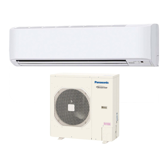
Panasonic CS-KS30NKU Technical & Service Manual
Hide thumbs
Also See for CS-KS30NKU:
- Operating instructions manual (19 pages) ,
- Installation instructions manual (33 pages)
Table of Contents
Advertisement
TECHNICAL & SERVICE MANUAL
CS-KS30NKU + CU-KS30NKUA
CS-KS36NKU + CU-KS36NKUA
DC INVERTER SPLIT SYSTEM AIR CONDITIONER
Indoor Model No.
CS-KS30NKU
CS-KS36NKU
CS-KS30NKU
CS-KS36NKU
IMPORTANT
These air conditioners employ new
refrigerant R410A.
Pay special attention when
servicing the unit.
Product Code No.
1 852 360 86
1 852 360 87
Indoor Unit
Outdoor Model No.
Product Code No.
CU-KS30NKUA
1 852 360 84
CU-KS36NKUA
1 852 360 85
Outdoor Unit
CU-KS30NKUA
CU-KS36NKUA
SM
700875
REFERENCE NO.
Advertisement
Chapters
Table of Contents
Troubleshooting

Related Manuals for Panasonic CS-KS30NKU


Summary of Contents for Panasonic CS-KS30NKU
- Page 1 TECHNICAL & SERVICE MANUAL CS-KS30NKU + CU-KS30NKUA CS-KS36NKU + CU-KS36NKUA DC INVERTER SPLIT SYSTEM AIR CONDITIONER Indoor Model No. Product Code No. Outdoor Model No. Product Code No. CS-KS30NKU 1 852 360 86 CU-KS30NKUA 1 852 360 84 CS-KS36NKU 1 852 360 87...
-
Page 2: Safety Precautions
SAFETY PRECAUTIONS • Before doing repair work, please read the " SAFETY PRECAUTIONS" carefully and fully understand them. • The precautionary items here are divided into " Warning" and " Caution" items. Items in particular which may cause death or serious injury to the service personnel if the work is not performed correctly, are included in the "... - Page 3 Warning If refrigerant gas blows off during the work, do not touch the refrigerant gas as it may cause frostbite. Prohibit If refrigerant gas leaks during the work, ventilate the room. If refrigerant gas catches fire, harmful gas may be generated. Do not mix any gas other than the specified refrigerant gas in the refrigerating cycle.
-
Page 4: Table Of Contents
Table of Contents Page SAFETY PRECAUTIONS ......................TABLE OF CONTENTS ........................1. OPERATING RANGE ........................2. SPECIFICATIONS 2-1. Unit Specifications ......................2-2. Major Component Specifications ..................2-3. Other Component Specifications ..................3. DIMENSIONAL DATA ........................4. REFRIGERANT FLOW DIAGRAM 4-1. Refrigerant Flow Diagram .................... - Page 5 Page 9. CHECKING ELECTRICAL COMPONENTS 9-1. Measurement of Insulation Resistance ................9-2. Checking Continuity of Fuse on PCB Ass'y ................. 10. REFRIGERANT R410A: SPECIAL PRECAUTIONS WHEN SERVICING UNIT 10-1. Characteristics of New Refrigerant R410A ................. 10-2. Checklist before Servicing ....................10-3.
-
Page 6: Operating Range
1. OPERATING RANGE Temperature Indoor Air Intake Temp. Outdoor Air Intake Temp. Maximum 95 °F DB / 71 °F WB 115 °F DB Cooling Minimum 67 °F DB / 57 °F WB 0 °F DB... -
Page 7: Specifications
2. SPECIFICATIONS 2-1. Unit Specifications Indoor Unit CS-KS30NKU Outdoor Unit CU-KS30NKUA < 230V > Voltage Rating 230V Single-Phase 60Hz Cooling Total Capacity BTU/h 30,600 ( 10,900 to 30,600 ) ( 3.2 to 9.0 ) Sensible Capacity 18,600 BTU/h Latent Capacity... - Page 8 Indoor Unit CS-KS30NKU Outdoor Unit CU-KS30NKUA < 208V > Voltage Rating 208V Single-Phase 60Hz Cooling Total Capacity BTU/h 30,600 ( 10,900 to 30,600 ) ( 3.2 to 9.0 ) Sensible Capacity 18,600 BTU/h Latent Capacity BTU/h 12,000 Air Circulation (Hi/Me/Lo)
- Page 9 Indoor Unit CS-KS36NKU Outdoor Unit CU-KS36NKUA < 230V > Voltage Rating 230V Single-Phase 60Hz Cooling Total Capacity BTU/h 34,000 ( 10,900 to 34,000 ) 10.0 ( 3.2 to 10.0 ) Sensible Capacity 20,700 BTU/h Latent Capacity BTU/h 13,300 Air Circulation (Hi/Me/Lo) /min (m 630 (1,070) / 530 (901) /412 (700) Moisture Removal (High)
- Page 10 Indoor Unit CS-KS36NKU Outdoor Unit CU-KS36NKUA < 208V > Voltage Rating 208V Single-Phase 60Hz Cooling Total Capacity BTU/h 34,000 ( 10,900 to 34,000 ) 10.0 ( 3.2 to 10.0 ) Sensible Capacity 20,700 BTU/h Latent Capacity BTU/h 13,300 Air Circulation (Hi/Me/Lo) /min (m 630 (1,070) / 530 (901) /412 (700) Moisture Removal (High)
-
Page 11: Major Component Specifications
2-2. Major Component Specifications 2-2-1. Indoor Unit Indoor Unit CS-KS30NKU Control PCB Part No. CB-CS-KS30NKU Controls Microprocessor Control Circuit Fuse 250V 3A Type Cross-Flow Q'ty ... Dia. and Length inch (mm) 1 ... D3-15/16 / L32-1 (D100/L838) Fan Motor Type DC Motor Model ... - Page 12 Indoor Unit CS-KS36NKU Control PCB Part No. CB-CS-KS36NKU Controls Microprocessor Control Circuit Fuse 250V 3A Type Cross-Flow Q'ty ... Dia. and Length inch (mm) 1 ... D3-15/16 / L32-1 (D100/L838) Fan Motor Type DC Motor Model ... Q'ty SIC-41CVJ-D847-1 ... 1 No.
- Page 13 2-2-2. Outdoor Unit Outdoor Unit CU-KS30NKUA P.C.Board Control P.C.B Noise Filer P.C.B H.I.C.Board Part No. CR-C3082-F POW-CH3082-B2 HIC-CH3072R-C1 Controls Microprocessor Circuit Fuse 400V 3.15A 250V 25A Compressor Type DC Twin Rotary (Hermetic) Compressor Model / Nominal Output C-9RVN273H0H / 2,250W Compressor Oil ...
- Page 14 Outdoor Unit CU-KS36NKUA P.C.Board Control P.C.B Noise Filer P.C.B H.I.C.Board Part No. CR-C3682-F POW-CH3082-B2 HIC-CH3072R-C1 Controls Microprocessor Circuit Fuse 400V 3.15A 250V 25A Compressor Type DC Twin Rotary (Hermetic) Compressor Model / Nominal Output C-9RVN273H0H / 2,500W Compressor Oil ... Amount Pints (cc) FV68S ...
-
Page 15: Other Component Specifications
2-3. Other Component Specifications Indoor Unit CS-KS30NKU CS-KS36NKU Outdoor Unit CU-KS30NKUA CU-KS36NKUA • Indoor heat exchanger sensor (Model:PTM-D51H-S6-1) • Indoor air temp sensor • Compressor temp sensor (Model:KTEC-35-135-1) (Model:TKS335B) 32 50 68 86 104 122 140 158 176 194 (10) (15) (20) (25) (30) (35) (40) (0) (10) (20) (30) (40) (50) (60) (70) (80) (90) Temperature °F (°C) -
Page 16: Dimensional Data
3. DIMENSIONAL DATA Indoor Unit CS-KS30NKU CS-KS36NKU Unit: inch(mm) (852-0-0010-196-00-0) - Page 17 Outdoor Unit CU-KS30NKUA CU-KS36NKUA...
-
Page 18: Refrigerant Flow Diagram
4. REFRIGERANT FLOW DIAGRAM 4-1. Refrigerant Flow Diagram Indoor Unit CS-KS30NKU Outdoor Unit CU-KS30NKUA CS-KS36NKU CU-KS36NKUA Indoor unit Outdoor unit Wide tube service Main Wide tube valve Accumulator Accumulator Muffler 5/8" High pressure switch (15.88 mm) H.P. Electric Narrow expansion... -
Page 19: Performance Data
5. PERFORMANCE DATA 5-1. Temperature Charts Indoor Unit CS-KS30NKU Outdoor Unit CU-KS30NKUA Cooling Characteristics (RH : 46%, Indoor fan speed : High fan) (60Hz, 230V) (1) Low pressure performance chart Lo fan Hi Fan (1.2) (1.1) (1.0) (0.9) (0.8) (0.7) - Page 20 Indoor Unit CS-KS36NKU Outdoor Unit CU-KS36NKUA Cooling Characteristics (RH : 46%, Indoor fan speed : High fan) (60Hz, 230V) (1) Low pressure performance chart Lo fan Hi Fan (1.2) (1.1) (1.0) (0.9) (0.8) (0.7) (-20) (-15) (-10) (-5) (10) (15) (20) (25) (30)
-
Page 21: Cooling Capacity
5-2. Cooling Capacity Indoor Unit : CS-KS30NKU Outdoor Unit : CU-KS30NKUA Power Supply : 230V Single Phase 60Hz < Cooling Capacity > RATING CAPACITY: 30,600 BTU/h AIR FLOW RATE: 630 CFM INDOOR OUTDOOR ENT. TEMP. AMBIENT TEMP. (18.3) (23.9) (29.4) (35.0) - Page 22 Indoor Unit : CS-KS36NKU Outdoor Unit : CU-KS36NKUA Power supply : 230V Single Phase 60Hz < Cooling Capacity > RATING CAPACITY: 34,000 BTU/h AIR FLOW RATE: 630 CFM INDOOR OUTDOOR ENT. TEMP. AMBIENT TEMP. (18.3) (23.9) (29.4) (35.0) (40.6) (46.1) 27,450 28,140 28,840...
-
Page 23: Cooling Capacity (Low Ambient)
5-3. Cooling Capacity (Low Ambient) Indoor Unit : CS-KS30NKU Outdoor Unit : CU-KS30NKUA Power supply : 230V Single Phase 60Hz < Cooling Capacity (Low Ambient) > RATING CAPACITY: 30,600 BTU/h AIR FLOW RATE: 630 CFM INDOOR OUTDOOR ENT. TEMP. AMBIENT TEMP. - Page 24 Indoor Unit : CS-KS36NKU Outdoor Unit : CU-KS36NKUA Power supply : 230V Single Phase 60Hz < Cooling Capacity (Low Ambient) > RATING CAPACITY: 34,000 BTU/h AIR FLOW RATE: 630 CFM INDOOR OUTDOOR ENT. TEMP. AMBIENT TEMP. (-17.8) (-15.0) (-9.4) (-3.9) (1.7) (7.2) (12.8)
-
Page 25: Air Throw Distance Charts
5-4. Air Throw Distance Charts Indoor Unit CS-KS30NKU Room air temp. : 80°F (26.7°C) Cooling Fan speed : High Horizontal distance (ft.) : Flap angle 0 , : Axis air velocity 0 : Flap angle 30 , : Axis air velocity 30... - Page 26 Indoor Unit CS-KS36NKU Room air temp. : 80°F (26.7°C) Cooling Fan speed High Horizontal distance (ft.) : Flap angle 0 , : Axis air velocity 0 : Flap angle 30 , : Axis air velocity 30...
-
Page 27: Electrical Data
6. ELECTRICAL DATA 6-1. Electrical Characteristics Indoor Unit CS-KS30NKU Outdoor Unit CU-KS30NKUA (1) Voltage:230V < > Cooling 230V Indoor UnitOutdoor Unit Complete Unit Fan Motor Fan Motor + Compressor Performance at 230V Single-phase 60Hz Rating conditions Running amp. 16.1 16.5... - Page 28 Indoor Unit CS-KS36NKU Outdoor Unit CU-KS36NKUA (1) Voltage:230V < > Cooling 230V Indoor UnitOutdoor Unit Complete Unit Fan Motor Fan Motor + Compressor Performance at 230V Single-phase 60Hz Rating conditions Running amp. 19.6 20.0 Power input 3,961 4,000 Rating conditions: Indoor air temperature: 80 °F (26.7 °C) DB / 67 °F (19.4 °C) WB Outdoor air temperature:...
-
Page 29: Electric Wiring Diagrams
6-2. Electric Wiring Diagrams Indoor Unit CS-KS30NKU CS-KS36NKU TERMINAL BASE GRN/YEL EVAPORATOR AC IN FLAP 5P (WHT) LAMP 9P (WHT) FLAP MOTOR 2P (WHT) CONTROLLER OPERATION SW PL ELEC J-B COIL 2P (WHT) COIL THERMISTOR 7P (WHT) ROOM THERMISTOR FAN MOTOR... - Page 30 Outdoor Unit CU-KS30NKUA CU-KS36NKUA 8FA2-5251-15300-0...
-
Page 31: Functions
7. FUNCTIONS 7-1. Operation Functions Emergency operation SENSOR DRY Emergency operation is available when the remote During DRY operation, the system adjusts the room controller malfunctions, has been lost, or otherwise temperature and fan speed according to the conditions in the room, in order to maintain a comfortable room environment. -
Page 32: Night Setback
HIGH POWER NIGHT SETBACK This function acts to raise the power but keeps the AC system in • When NIGHT SETBACK operation is set, the temperature and the same operating mode. fan speed settings will be adjusted automatically to allow This function is set with the HIGH POWER button on the remote comfortable sleep. - Page 33 Noise Reducing Control (Outdoor Unit) The noise reducing control is the function used for silent operation of the air conditioner by means of setting the dip switch on the outdoor unit P.C.Board to control the fan and compressor's motor speed. When this function is used, the cooling ability is slightly degraded.
- Page 34 Maximum Current Value Change Function The maximum current value is changed to 14A (for CU-KS30NKUA) or 17A (for CU-KS36NKUA) to prevent power breaker tripping. (It is set to 24A when the unit is delivered from the factory.) 1. When the high load is given (Outside temperature is high in the cooling operation), NOTE the capacity is reduced.
-
Page 35: Protective Functions
• When the cause of the increase in electrical current is rectified, the system will resume operation in the original mode. < > CS-KS30NKU Cooling Dry Peak current cut-off trips 25.0 Hz down 22.0 <... -
Page 36: Troubleshooting (Before Calling For Service)
8. TROUBLESHOOTING (BEFORE CALLING FOR SERVICE) 8-1. Precautions before Performing Inspection or Repair After checking the self-diagnostics monitor, turn the power OFF before starting inspection or repair. High-capacity electrolytic capacitors are used inside the outdoor unit controller (inverter). They retain an electrical charge (charging voltage DC 310V) even after the power is turned OFF, and some time is required for the charge to dissipate. - Page 37 (1) Self-diagnostics Lamps INDOOR UNIT (1) OPERATION lamp (2) TIMER lamp OPERATION TIMER ON/OFF Since the indications cover various units, the corresponding parts listed below may not be present in some models..OFF ..BLINKING ..ON INDICATION ON INDOOR UNIT TIMER OPERATION ALARM...
- Page 38 (2) If the self-diagnostics function fails to operate No indicators illuminate and the Check the indoor unit. indoor fan does not rotate. Check the power voltage. Blown Is the fuse blown? Normal Replace the circuit board or the fuse. Replace the controller.
-
Page 39: Checking The Indoor And Outdoor Units
8-3. Checking the Indoor and Outdoor Units (1) Checking the indoor unit Control Check items (unit operation) • The rated voltage must be present between inter-unit wirings 1 and 2. Use the remote controller to operate the unit in "TEST run" mode. To determine •... - Page 40 (3) Serial Communication Error Identification Procedure If the lamps on the main body show the following conditions after the completion of self-diagnostics, a communication error between the indoor unit and outdoor unit might be considered. In such a case, identify the breakdown section by using the following procedure. NOTE Refer to "Method of Self-Diagnostics"...
- Page 41 ( Continued from the previous page A. ) ( Continued from the previous page B. ) Is the voltage of about DC22V to 24V given between the terminals 2 and 3 on the indoor unit terminal strip (Serial Communication Line) ? (Fig.
- Page 42 (3-2) Alarm Code : E07/P04/P05/P20/P27 Troubleshooting Serial Communication Outdoor Unit Power 1. Turn off the power and wait until the power lamp (LED) of the outdoor unit controller is turned OFF. 2. Disconnect the cable from the terminal 3 on the Outdoor Indoor Unit unit terminal strip.
-
Page 43: Trouble Diagnosis Of Fan Motor
8-4. Trouble Diagnosis of Fan Motor 8-4-1. Indoor Fan Motor This indoor DC fan motor contains an internal control PCB. Therefore, it is not possible to measure the coil resistance, and the following procedure should be used to check the motor. To perform diagnosis, operate the unit in cooling mode with indoor fan speed "High". -
Page 44: Outdoor Fan Motor
8-4-2. Outdoor Fan Motor This outdoor DC fan motor contains an internal control PCB. Therefore, it is not possible to measure the coil resistance, and the following procedure should be used to check the motor. Perform the trouble diagnosis by Test Run mode described on Installation Instructions of indoor unit. Important: (A) Turn OFF the power before connecting or disconnecting the motor connectors. -
Page 45: Noise Malfunction And Electromagnetic Interference
8-5. Noise Malfunction and Electromagnetic Interference An inverter A/C operates using pulse signal control and high frequencies. Therefore, it is susceptible to the effects of external noise, and is likely to cause electromagnetic interference with nearby wireless devices. A noise filter is installed for ordinary use, preventing these problems. However, depending on the installation conditions, these effects may still occur. -
Page 46: Checking Electrical Components
9. CHECKING ELECTRICAL COMPONENTS 9-1. Measurement of Insulation Ground wire Resistance Clip The insulation is in good condition if the resistance exceeds 1M ohm. Probe 9-1-1. Power Supply Cord Insulation Clamp the grounding wire of power cord with the lead tester Fig. -
Page 47: Checking Continuity Of Fuse On Pcb Ass'y
9-2. Checking Continuity of Fuse on Fuse PCB Ass'y Remove the PCB Ass'y from the electrical component box. Then pull out the fuse from the PCB Ass'y. (Fig. 5) Check for continuity using a multimeter as shown in PCB Ass'y Fig. -
Page 48: Refrigerant R410A: Special Precautions When Servicing Unit
10. REFRIGERANT R410A: SPECIAL PRECAUTIONS WHEN SERVICING UNIT 10-1. Characteristics of New Refrigerant R410A 10-1-1. What is New Refrigerant R410A? R410A is a new refrigerant that contains two types of pseudo-non-azeotropic refrigerant mixture. Its refrigeration capacity and energy efficiency are about the same level as the conventional refrigerant, R22. 10-1-2. -
Page 49: Checklist Before Servicing
10-2. Checklist before Servicing Use a clutch-type flare tool for R410A or the conventional flare tool. Note that sizes of the resultant flares differ between these two tools. Where a conventional flare tool is used, make sure to observe A Specification (amount of extrusion) by using the flare spacer. -
Page 50: Tools Specifically For R410A
10-3. Tools Specifically for R410A For servicing, use the following tools for R410A Tool Distinction Tool Name Gauge manifold Charging hose Gas leak detector Refrigerant cylinder Charging cylinder Refrigerant recovery unit Vacuum pump with anti-reverse flow (*1) Tools specifically for R410A (Solenoid valve-installed type, which prevents oil from flowing back into the unit when the power is off, is recommended.) Vacuum pump (*2)...can be used if the following adapter is attached. -
Page 51: In Case Of Compressor Malfunction
10-5. In Case of Compressor Malfunction Should the compressor malfunction, be sure to make the switch to a replacement CAUTION compressor as quickly as possible. Use only the tools indicated exclusively for R410A. See "10-3. Tools Specifically for R410A." 10-5-1. Procedure for Replacing Compressor (1) Recovering refrigerant Any remaining refrigerant inside the unit should not be released to the atmosphere, but recovered using the... - Page 52 Configuration and characteristics of cylinders (5) Recharging Valve Be sure to charge the specified amount of refrigerant in liquid state using the service port of the wide tube service valve. The proper amount is listed on the unit's nameplate. When the entire amount cannot be charged all at once, charge gradually while operating the unit in Cooling Operation.
-
Page 53: In Case Refrigerant Is Leaking
10-6. In Case Refrigerant is Leaking Never attempt to charge additional refrigerant when refrigerant has been leaking CAUTION from the unit. Follow the procedure described below to locate points of leaks and carry out repairs, then recharge the refrigerant. (1) Detecting Leaks Use the detector for R410A to locate refrigerant leak points. -
Page 54: Charging Additional Refrigerant
10-7. Charging Additional Refrigerant 10-7-1. When Tubes are Extended Observe the proper amount of refrigerant as stated in this service manual or the installation manual that came with the indoor unit. Charge additional refrigerant in liquid state only. Never charge additional refrigerant if refrigerant is leaking from the unit. Follow CAUTION instructions given in "10-6. -
Page 56: Appendix A Operating Instructions
APPENDIX A Operating Instructions CS-KS30NKU + CU-KS30NKUA CS-KS36NKU + CU-KS36NKUA (852-6-4181-220-00-2) -
Page 57: Operating Instructions
Operating Instructions Split System Air Conditioner Model No. Indoor Units Outdoor Units CS-KS30NKU CU-KS30NKUA CS-KS36NKU CU-KS36NKUA This air conditioner uses the refrigerant R410A. Before operating the unit, read these operating instructions thoroughly and keep them for future reference. Panasonic Corporation... -
Page 58: Features
FEATURES This air conditioner is an inverter type unit that automatically adjusts capability as appropriate. Details on these functions are provided below; refer to these descriptions when using the air conditioner. • Microprocessor Controlled Operation • Air Sweep Control The interior compartment of the remote controller contains This function moves a flap up and down in the air outlet, several features to facilitate automatic operation, easy directing air in a sweeping motion around the room and... -
Page 59: Installation Location
INSTALLATION LOCATION • To prevent possible hazards from insulation failure, the unit must be grounded. • We recommend that this air conditioner be installed • Do not clean inside the indoor and outdoor units by users. properly by qualified installation technicians in Engage authorized dealer or specialist for cleaning. -
Page 60: Names Of Parts
NAMES OF PARTS UNIT DISPLAY AND OPERATION BUTTON Air Intakes INDOOR UNIT INDOOR UNIT OPERATION lamp TIMER lamp REMOTE CONTROL receiver Air Outlet Remote Controller Drain Hose Refrigerant Tubes OPERATION button (ON/OFF) OUTDOOR UNIT IMPORTANT Avoid using radio equipment such as mobile phone near (within 4 ft. - Page 61 REMOTE CONTROLLER (DISPLAY) Displayed when transmitting data Displayed when setting temperature Displayed when indoor unit sensor is in use Displayed when temperature is shown Displayed when setting timer Symbols (1) Operation mode (4) Timer 24-hour clock with ON/OFF MILD DRY ......program Timer .......
- Page 62 REMOTE CONTROLLER Transmitter When you press the buttons on the remote controller, the mark appears in the display to transmit the setting changes to the receiver in the air conditioner. Display Information on the operating conditions is displayed while the remote controller is switched on.
- Page 63 Sensor A temperature sensor inside the remote controller senses the room temperature. ON/OFF operation button This button is for turning the air conditioner on and off. 1 HR. TIMER button (1-HOUR OFF TIMER) : When you press this button, regardless of whether the unit is operating or stopping, the unit operates for one hour and then shuts down.
-
Page 64: Using The Remote Controller
USING THE REMOTE CONTROLLER HOW TO INSTALL BATTERIES HOW TO USE THE REMOTE CONTROLLER When using the remote controller, always point the unit’s transmitter head directly at the air conditioner’s receiver. Air Conditioner (Indoor unit) Receiver ACL button (Transmitter head) Remote Controller Slide the cover in the direction indicated by the arrow and remove Install two AAA alkaline batteries. -
Page 65: Operation With The Remote Controller
OPERATION WITH THE REMOTE CONTROLLER 1. Operation 2. Adjusting the Fan Speed A. Automatic fan speed Simply set the FAN SPEED selector button to the position. This automatically sets the best fan speed for the room temperature. B. Manual fan speed If you want to adjust fan speed manually during operation, just set the FAN SPEED selector button as desired. -
Page 66: Night Setback Mode
4. Night Setback Mode 5. QUIET Mode QUIET Mode is used to reduce the fan sound of the indoor unit. Press the QUIET button. Night Setback Mode is used for saving energy. mark appears in the display. Press the NIGHT SETBACK button while unit is operating. (except To cancel, press QUIET button again. -
Page 67: Unoccupied Mode
7. UNOCCUPIED Mode In Cooling Mode: ( (1) When the room temperature rises above 89°F, Cooling Operation will begin. (2) When the room temperature drops below 82°F, Cooling Operation will stop. The above actions will repeat so that the room temperature is maintained at about 86°F. -
Page 68: Special Remarks
SPECIAL REMARKS SETTING THE TIMER ‘‘DRY’’ ( ) Operation How it works? • Once the room temperature reaches the level that was set, the unit’s operation frequency is changed automatically. • During DRY operation, the fan speed automatically runs at lower speed for providing a comfortable breeze. - Page 69 2. How to set the OFF time 4. How to set daily ON/OFF repeat timer (Example) To stop the air conditioner at 11:00 am. (Example) To start operation at 7:10 am. and stop the air conditioner at 11:00 am. 10:30 pm. 7:10 am.
-
Page 70: Using The 1-Hour Off Timer
USING THE 1-HOUR OFF ADJUSTING THE AIRFLOW TIMER DIRECTION 1. Horizontal 1. 1-Hour OFF Timer The horizontal airflow can be adjusted by moving the vertical vanes with your hands to the left or right. CAUTION This function causes the unit to operate for one hour and then When the humidity is high, the vertical vanes should be in the stop, regardless of whether the unit is on or off when this front position during the cooling or dehumidifying operation. -
Page 71: Operation Without The Remote Controller
CAUTION Never use solvents, or harsh CAUTION chemicals when cleaning the indoor unit. Do not wipe the plastic casing • Use the FLAP button on the remote controller to adjust the using very hot water. position of the flap. If you move the flap by hand, the flap Some metal edges and the fins are position according to the remote controller and the actual sharp and may cause injury if... -
Page 72: Troubleshooting (Before Calling For Service)
Cleaning the main unit and Remote Controller TROUBLESHOOTING • Wipe clean using a soft, dry cloth. (BEFORE CALLING FOR SERVICE) • To remove stubborn dirt, moisten a cloth in warm water no hotter than 104 °F, wring thoroughly, and then wipe. If your air conditioner does not work properly, first check the following •... -
Page 73: Operating Range
OPERATING RANGE The air conditioner is operable within the temperature ranges as listed below: Temperature Indoor air Outdoor air temperature temperature COOLING Max. 95 °F DB / 115 °F DB 71 °F WB Min. 67 °F DB / 0 °F DB 57 °F WB WIRED REMOTE CONTROLLER A separately sold wired remote controller (CZ-RD515U) -
Page 74: Specifications
SPECIFICATIONS Outdoor Unit Indoor Unit Model No. CU-KS30NKUA CS-KS30NKU Power Source Single-phase, 208-230 V, 60 Hz 9.00 [ 3.20 ~ 9.00 ] Cooling Capacity 30,600 [ 10,900 ~ 30,600 ] BTU/h Heating Capacity BTU/h Cooling Outdoor (Hi) dB(A) Operation Operation... - Page 76 APPENDIX B INSTALLATION INSTRUCTIONS CS-KS30NKU + CU-KS30NKUA CS-KS36NKU + CU-KS36NKUA (852-6-4190-586-00-0)
-
Page 77: Installation Instructions
1-4. Type of Copper Tube and Insulation Material 1-5. Additional Materials Required for Installation Model No. Indoor Unit Outdoor Unit INSTALLATION SITE SELECTION ....5 2-1. Indoor Unit CS-KS30NKU CU-KS30NKUA 2-2. Outdoor Unit CS-KS36NKU CU-KS36NKUA HOW TO INSTALL THE INDOOR UNIT ... 13 Power Source: 3-1. -
Page 78: Important
IMPORTANT! When Transporting Please Read Before Starting Be careful when picking up and moving the indoor and out- door units. Get a partner to help, and bend your knees when This air conditioning system meets strict safety and operating lifting to reduce strain on your back. Sharp edges or thin alu- standards. - Page 79 Others the flare and union tubes before connecting them, CAUTION then tighten the nut with a torque wrench for a leak- free connection. the refrigeration system. Escaped refrigerant gas, on contact with fire or heat, can produce dangerously or re-installation, and while repairing refrigeration parts. toxic gas.
-
Page 80: General
(30 cm to 40 cm) to dampen vibration between units. Table 2 Narrow Tube Wide Tube Model Outer Dia. Thickness Outer Dia. Thickness CS-KS30NKU 3/8" (9.52 mm) 0.0314" (0.8 mm) 5/8" (15.88 mm) 0.0393" (1.0 mm) CS-KS36NKU 3/8" (9.52 mm) 0.0314" (0.8 mm) 5/8" (15.88 mm) -
Page 81: Additional Materials Required For Installation
(ft.) (ft.) (ft.) (oz./ft.)* If the outdoor unit is higher CS-KS30NKU 10 to 100 0.43 CS-KS36NKU If the outdoor unit is lower * If total tubing length becomes 100 to 164 ft. (Max.), charge additional refr igerant (R410A) b y 0.43 oz./ft. -
Page 82: Outdoor Unit
2-2. Outdoor Unit Exhaust fan AVOID: Hot air heat sources, exhaust fans, etc. (Fig. 4) Heat source damp, humid or uneven locations. Outdoor unit choose a place as cool as possible. choose a place that is well ventilated. install in a location where at least two sides are unob- structed, so that the flow of air at the intake port or Fig. - Page 83 2-2-1. Installing the Unit in an Area with High Winds and in a Snowy Area Countermeasures against snow and wind Fig. 5e 2-2-2. Precautions for Installation in a Snowy Area Fig. 5f Fig. 5g...
- Page 84 2-2-3. Dimensions of Wind-proof Duct Reference diagram for CU-KS30NKUA, CU-KS36NKUA Air Intake Unit: inch Air Intake Hole for anchor bolt (4-R1/4") / Anchor bolt : 3/8" or M10 discharge discharge 6-11/16" 25-31/32" (4-11/32") 25-3/16" 37-1/32" 11-13/16" 13-3/8" 2-11/16" 21-25/32" (12-9/16") Air discharge discharge discharge...
- Page 85 Required space around the outdoor unit CAUTION CAUTION CAUTION...
- Page 86 2-2-4. Dimensions of Snow-proof Duct Reference diagram for CU-KS30NKUA, CU-KS36NKUA Unit: inch 27-5/8" (11-5/8") Air Intake Hole for anchor bolt (4-R1/4") / Anchor bolt: 3/8" or M10 Air discharge (8-15/16") 25-31/32" 4-11/32" 39-1/4" 25-13/32" 27-7/32" (11-15/16") 3/32" 13-3/8" discharge Air Intake Reference diagram for snow-proof duct (locally purchased): STK-BDV80E Unit: inch Unit top, snow-proof duct...
- Page 87 Reference diagram for snow-proof duct Space requirements for setting CU-KS30NKUA, CU-KS36NKUA with STK-BDV80E [Obstacle to the front of unit] [Obstacle to the rear of unit] Note:...
- Page 88 [Obstacles to the front and rear of unit] [Installation in front-rear rows]...
-
Page 89: How To Install The Indoor Unit
3. How to Install the Indoor Unit 3-1. Remove the Rear Panel from the Unit (1) Remove and discard the set screw on the rear panel. (Fig. 6) (2) Press the 2 marks on the frame cover and disengage Set screw only for transportation the stationary tabs from the frame. -
Page 90: Install The Rear Panel On The Wall
(4) Using a sabre saw, key hole saw or hole-cutting drill NOTE attachment, cut a hole in the wall. See Table 4 and Hole should be made at a slight downward slant to the Fig. 10. outdoor side. Table 4 Indoor Outdoor side... -
Page 91: Removing And Installing The Grille
Front panel 3-4. Removing and Installing the Grille Basically, these models can be installed and wired with- out removing the grille. If access to any internal part is needed, follow the steps as given below. How to remove the grille (1) Open the front panel until it is nearly horizontal, grasp the sections near the front panel arms on both sides, Anti-mold filter... -
Page 92: Shape The Indoor Side Tubing
3-5. Shape the Indoor Side Tubing (1) Arrangement of tubing by direction a) Right or left tubing Cut out the corner of the right/left frame with a hacksaw or the like. (Figs. 20 and 21) b) Right-rear or left-rear tubing In this case, the corner of the frame need not be cut. -
Page 93: Wire Size And Length
3-7. Wire Size and Length Regulations on wiring diameter differ from locality to locality. For field wiring requirements, please refer to your local elec- trical codes. Carefully observe these regulations when carrying out the installation. NOTE Refer to the wiring system diagram (Fig. 23) for the meaning of (A), (B), and (C) in Table 5. Refer to your local codes or in the absence of local codes see the National Electric Code: ANSI/NFPA70. -
Page 94: Wiring Instructions For Inter-Unit Connections
3-8. Wiring Instructions for Inter-unit Connections (1) Insert the inter-unit wiring (according to local codes) into the through-the-wall PVC pipe. Run the wiring toward the indoor side allowing approx. 10" (25 cm) to extend from the wall face. (Fig. 24) (2) Grasp both ends of the front panel, push the arms towards the outside, and remove the front panel by opening it towards the front and pulling it towards... - Page 95 Loose wiring may cause the WARNING terminal to overheat or result in unit malfunction. A fire hazard may also exist. Therefore, be sure all wiring is tightly connected. When connecting each power wire to the corresponding terminal, follow the instructions “How to connect wiring to the terminal”...
-
Page 96: Mounting
3-9. Mounting (1) To install the indoor unit, mount the indoor unit onto the 3 tabs on the upper part of the rear plate. (2) Hold down the air discharge outlet and press the lower part of the indoor unit until it clicks to securely fasten to the 2 tabs on the lower part of the rear plate. - Page 97 Left-side tubing (1) Lead the tubing and drain hose through the wall, allowing sufficient length for connection. Then bend Rear panel the tubing using a tube bender to make the attach- Hole in wall ment. (Fig. 38) (2) Switch the drain hose and drain cap. Switching drain hose and drain cap Bent part Narrow tube...
-
Page 98: Frame Fastening Method
To unmount indoor unit Press the 2 marks on the lower part of the indoor unit and unlatch the tabs. Then lift the indoor unit and unmount. (Fig. 42) 3-10. Frame Fastening Method (1) Remove the screw cover on the bottom surface. (Fig. -
Page 99: How To Install The Outdoor Unit
4. How to Install the Outdoor Unit First refer to Section 2. Installation Site Selection. 4-1. Wiring Instructions for the Outdoor Unit Regulations on wire size differ from locality to locality. For field wiring requirements, please refer to your local elec- trical codes. -
Page 100: Refrigerant Tubing
5. Refrigerant Tubing Deburring After Before 5-1. Use of the Flaring Method Many of the conventional split system air conditioners employ the flaring method to connect refrigerant tubes which run between indoor and outdoor units. In this method, the copper tubes are flared at each end and connected with flare nuts. -
Page 101: Connecting Tubing Between Indoor And Outdoor Units
5-4. Connecting Tubing between Indoor and Torque wrench Outdoor Units a) Tightly connect the indoor side refrigerant tubing exten- Spanner ded from the wall with the outdoor side tubing. (Fig. 52) Indoor unit b) To fasten the flare nuts, apply specified torque as: Table 6 Outdoor unit Tube Dia. -
Page 102: Air Purging
6. Air Purging Indoor unit Air and moisture remaining in the refrigerant system have undesirable effects as indicated below. Therefore, they must be purged completely. pressure in the system rises operating current rises cooling (or heating) efficiency drops Outdoor unit moisture in the air may freeze and block capillary tubing water may lead to corrosion of parts in the refrigerant system... - Page 103 (5) With the vacuum pump still running, close the “Lo” knob of the manifold valve. Then stop the vacuum pump. 90 (1/4 turn) Vacuum hose to manifold valve (6) With the hex wrench, turn the valve stem on the nar- Hex wrench row tube service valve counter-clockwise by 90 degrees (1/4 turn) for 10 seconds, and then turn the...
- Page 104 How to Test Run the Air Conditioner After turning on the power of the air conditioner, use the remote controller and follow the steps below to conduct the test run. (1) Set the remote controller in Test Run mode. (Fig. 59a) a) Press and hold the QUIET button and the 1HR.
-
Page 105: Basic Functions Of The Service Valves
Basic Functions of the Service Valves The basic functions of the service valves are given in Table 8 below. Table 8 Narrow Tube Service Wide Tube Service Action Valve (2-Way) Valve (3-Way) O-ring Valve cap CLOSED Stem Shipping Fully OPEN Operating and test running the air conditioner... -
Page 106: Service Valve Connections
Service Valve Connections Table 9 Fig. 60c Fig. 60d Tube Dia. Tightening Torque 1/4" (6.35 mm) 21/32" (17 mm) Approx. 120 – 160 lbs·in (140 – 180 kgf·cm) Be sure to tighten the flare nut using the CAUTION 3/8" (9.52 mm) 7/8"... -
Page 107: Address Switch
8. Address Switch 8-1. Address Setting of the Remote Controller The address can be set in order to prevent interference between remote controllers when 2 indoor units are installed near each other. The address is normally set to “A.” To set a different address, it is necessary to change the address on the second remote controller. - Page 108 DC1111-0...