Sony WM-EX190 Service Manual
Hide thumbs
Also See for WM-EX190:
- Operating instructions (2 pages) ,
- Specifications (2 pages) ,
- Operating instructions manual (8 pages)
Table of Contents
Advertisement
WM-EX190/EX192
SERVICE MANUAL
Ver 1.0 2000. 01
MICROFILM
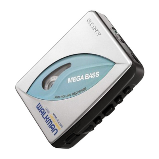
Photo : WM-EX192
SPECIFICATIONS
• Power requirements
3V DC batteries R6 (AA) × 2
• Dimensions
82 × 111.5 × 34.5 mm
(w / h/ d) incl. projecting parts and controls
• Mass
Approx. 115 g / Approx. 190 g incl.
batteries and a cassette
• Supplied accessories
Stereo headphones or Stereo earphones (1) / Belt clip (1)
Design and specifications are subject to change without notice.
Canadian Model
Model Name Using Similar Mechanism
Tape Transport Mechanism Type
CASSETTE PLAYER
US Model
WM-EX190
AEP Model
E Model
Chinese Model
WM-EX190/192
NEW
MT-WMEX192-114
Advertisement
Table of Contents

Related Manuals for Sony WM-EX190


Summary of Contents for Sony WM-EX190
- Page 1 WM-EX190/EX192 SERVICE MANUAL US Model Canadian Model WM-EX190 Ver 1.0 2000. 01 AEP Model E Model Chinese Model WM-EX190/192 Photo : WM-EX192 Model Name Using Similar Mechanism Tape Transport Mechanism Type MT-WMEX192-114 SPECIFICATIONS • Power requirements 3V DC batteries R6 (AA) × 2 •...
-
Page 2: Table Of Contents
TABLE OF CONTENTS GENERAL Flexible Circuit Board Repairing ······································································ 2 • Keep the temperature of the soldering iron aroud 270˚ C during repairing. DISASSEMBLY • Do not touch the soldering iron on the same conductor of the 2-1. Cabinet (REAR) ································································· 3 circuit board (within 3 times). -
Page 3: Disassembly
SECTION 2 DISASSEMBLY • This set can be disassembled in the order shown below. Cabinet (rear) Main board Mechanism deck Belt Motor Lid assy, cassette Pinch lever (N) assy Head, magnetic Note : Follow the disassembly procedure in the numerical order given. 2-1. -
Page 4: Main Board
2-2. MAIN BOARD 1 Remove the solders. 2 Screw (M1.4) 3 MAIN board (There is a claw.) Claw 2-3. LID ASSY, CASSETTE 3 Release the catch 2 Spring (torsion) 1 Open the lid, cassette 5 Lid assy, cassette 4 Release the catch —... -
Page 5: Mechanism Deck
2-4. MECHANISM DECK 1 Remove the mechanism deck in the direction of the arrow. (There two claws.) Two claws 2-5. BELT, MOTOR, PINCH LEVER (N) ASSY, “HEAD, MAGNETIC” 5 Two screws (M1.4) 6 Head,magnetic (playback) 2 Two screws (M1.4) Belt threading 4 Pnch lever (N) assy Wheel assy (sp), capstan Motor (reel/capstan) -
Page 6: Electrical Adjustment
SECTION 3 SECTION 4 MECHANICAL ADJUSTMENTS ELECTRICAL ADJUSTMENT PRECAUTION PRECAUTION Clean the following parts with a denatured-alcohol-moistened • Supplied voltage : 3.0 V swab : • Switch position playback head pinch roller AVLS switch : NORM capstan rubber belt MEGA BASS switch : OFF/NORM Demagnetize the playback head with a head demagnetizer. -
Page 7: Diagrams
WM-EX190/EX192 SECTION 5 DIAGRAMS 5-1. BLOCK DIAGRAM AVLS NORM LIMIT S305-2 S305-1 S503 (EX192) GROOVE MEGA BASS NORM (EX190) MEGA BASS V REF BOOST RV301 VOLUME J301 HP901 PLAYBACK HEAD FWD/REV V REF M901 REEL/CAPSTAN MOTOR OPERATION OPERATION PULSE LOGIC... -
Page 8: Printed Wiring Board
WM-EX190/EX192 5-2. PRINTED WIRING BOARD • Semiconductor MAIN BOARD Location DRY BATTERY M901 Ref. No. Location SIZE "AA" REEL/CAPSTAN (IEC DESIGNATION R6) MOTOR TP11 D150 2PCS, 3V C335 TP10 D302 R327 J301 R109 R107 IC301 Q301 R209 R207 TP15 S305... -
Page 9: Schematic Diagram
WM-EX190/EX192 5-3. SCHEMATIC DIAGRAM • Refer to page 13 for IC Block Diagram. Note on Schematic Diagram: • All capacitors are in µF unless otherwise noted. pF: µµF 50 WV or less are not indicated except for electrolytics and tantalums. -
Page 10: Ic Block Diagram
WM-EX190/EX192 SECTION 6 5-4. IC BLOCK DIAGRAM EXPLODED VIEWS NOTE: • -XX, -X mean standardized parts, so they may • The mechanical parts with no reference number • Color Indication of Appearance Parts in the exploded views are not supplied. -
Page 11: Main Board Section
6-2. MAIN BOARD SECTION Ref. No. Part No. Description Remarks Ref. No. Part No. Description Remarks 3-703-816-73 SCREW (M1.4), SPECIAL HEAD 3-040-912-01 TERMINAL (+), BATTERY A-3021-303-A MAIN BOARD, COMPLETE (EX190:FR) 3-019-944-01 BUTTON (STOP) A-3021-304-A MAIN BOARD, COMPLETE(EX190:US,CND,AEP) 3-019-943-01 BUTTON (REW) A-3021-305-A MAIN BOARD, COMPLETE (EX190:E) 3-019-941-01 BUTTON (PLAY) A-3021-306-A MAIN BOARD, COMPLETE (EX192:AEP,E,EA) -
Page 12: Mechanism Section-1
6-3. MECHANISM SECTION-1 HP901 M901 Ref. No. Part No. Description Remarks Ref. No. Part No. Description Remarks 3-013-560-11 BELT X-3369-749-1 PINCH LEVER (N) ASSY 3-703-816-07 SCREW (M1.4), SPECIAL HEAD 3-920-996-01 SPRING (PINCH N) 3-019-776-01 GEER (REEL-S) M901 1-763-073-11 MOTOR (REEL/CAPSTAN)(WITH PULLY) 3-703-816-73 SCREW (M1.4), SPECIAL HEAD HP901 1-500-640-11 HEAD, MAGNETIC (PLAYBACK) -
Page 13: Mechanism Section-2
6-4. MECHANISM SECTION-2 Ref. No. Part No. Description Remarks Ref. No. Part No. Description Remarks 3-921-797-01 WASHER 3-728-091-01 WASHER, STOPPER X-3378-363-1 CHASSIS ASSY (GL/O-99) 3-019-778-01 SLEEVE (MS) 3-938-628-11 SPRING (PLAY-CP) 3-921-335-03 WASHER, LEVER 3-019-773-01 GEAR (AS) 3-920-990-02 SPRING (UD), COMPRESSION X-3374-598-1 CLUTCH ASSY (S) 3-019-774-01 GEAR (BS) 3-022-093-01 SPRING (FR-S) -
Page 14: Electrical Parts List
SECTION 7 MAIN ELECTRICAL PARTS LIST NOTE: • Items marked “*” are not stocked since they • COILS are seldom required for routine service. Some uH: µH When indicating parts by reference number, delay should be anticipated when ordering these •... - Page 15 MAIN Ref. No. Part No. Description Remarks Ref. No. Part No. Description Remarks JR32 1-216-296-91 SHORT R210 1-216-813-11 RES-CHIP 1/16W JR33 1-216-296-91 SHORT (EX190:E/EX192:AEP,E,EA) JR34 1-216-296-91 SHORT R210 1-216-821-11 RES-CHIP 1/16W JR35 1-216-296-91 SHORT (EX192:FR) R210 1-216-817-11 RES-CHIP 1/16W JR36 1-216-296-91 SHORT (EX190:US,CND,AEP,FR) JR37...
- Page 16 WM-EX190/EX192 Sony Corporation 2000A1678-1 Personal Audio Division Company 9-927-642-11 Printed in Japan ©2000.1 — 20 — Published by General Engineering Dept.