Table of Contents
Advertisement
Advertisement
Table of Contents

Summary of Contents for LENCO SVB
- Page 1 The world leader in trim tab systems & hatch lift innovation. Owner's Manual...
-
Page 2: Table Of Contents
Template....... . 22 The contents of this manual are subject to change without notice and do not constitute a commitment on the part of Lenco Marine, Inc. - Page 3 They are optional on some boats but should be as standard as power trim and tilt. Lenco trim tabs make your boat ride smoother, Lenco Trim Tabs: drier, faster and with increased safety whether on a small skiff or a mega-yacht.
-
Page 4: Overview
#124SSR reduce drag, increase speed and improve the fuel efficiency of your boat. The operation of Lenco Trim Tabs is basic. The two stainless steel planes are mounted with the actuators on the transom of the boat. When the tabs are lowered, the water flow is redirected creating an upward force at the stern of the boat. -
Page 5: Special Conditions
Trim Tab Operation sPeCIal COnDITIOns HeaD sea Head Sea — (Waves or current running directly against the course of a boat) Lower both tabs slightly by pressing BOW DOWn on both sides. This brings bow down while maintaining speed. This adjustment allows the hull of the boat to absorb the impact of the waves, resulting in a more efficient and smoother ride. -
Page 6: Tools And Materials List
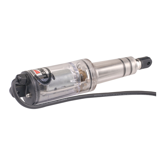
Installation of Trim Tab Blades note: when drilling out the screw hole pattern for the trim tab hinge you 1. To begin, determine where the Lenco Trim may drill through the transom. Hinge Tab Kit will be installed. Note: When laying... - Page 7 Trim Tab Installation Instructions Installation of Upper and Lower standard Mount Mounting Brackets & Actuators Fig. 2.1 1. Loosely attach the upper mounting bracket (bracket with four holes) to the top of the actuator 14" (35.56 cm) max. using the 5/16-18" X 1-3/4" (4.45 cm) large hex height needed head bolt and 5/16-18 hex nut provided.
- Page 8 If, however, you are prevented from nOTe: saCrIFICIal anODes FOr drilling a hole through the transom at yOur lenCO ss TrIM TaBs the bracket location, using the 3/8" Be aware that stray currents in your (.95 cm) drill bit, simply drill a 3/8" (.95 marina or in a visiting marina can cm) hole 4"...
-
Page 9: Installation Instructions
Trim Tab Installation Instructions After mounting the control box, feed Each digital tactile switch has a retractor the key pad cable up thru the 2" hole wire (orange) coming from the control and connect it to the backside of the box. -
Page 10: Operation
(1 to 2 seconds) the L.E.D. displays show one up arrow on each side The operation of all Lenco switches is of the switch. This shows that both tabs are based on the position of the bow. To fully retracted. - Page 11 Switch Wiring #15069-001 (124SSR) Owner’s Manual...
- Page 12 Switch Wiring #15070-001 (123SC) LENCO MARINE...
- Page 13 Switch Wiring #15071-001 (123DR) Owner’s Manual...
- Page 14 Switch Wiring Double Rocker # 10222-211 (122) LENCO MARINE...
- Page 15 RetroFit Kit for Bennett Trim Tabs Installation Instructions RetroFit Kit for Bennett Trim Tabs Installation Instructions Lenco Marine’s RetroFit Kit is designed as a direct replacement for the Bennett hydraulic power unit (HPU) on systems using Bennett's 4-ring standard trim tab actuators.
- Page 16 3) Now you will need to hook up the Lenco Actuator wires inside the bilge/rigging area. First cut the wire connector from the Please follow the instructions and Bennett wire harness where the pump drawings carefully.
-
Page 17: Wiring Diagram
RetroFit Kit for Bennett Trim Tabs Wiring Diagram Owner’s Manual... -
Page 18: Installation/Operation
• Lenco hatch lifts are offered in both 12 and 24 volts. OPeraTIOn The function of the Lenco Hatch Lift System is simple. Since the hatch lift is based around a ball screw it is able to push a heavy load and remain at a constant position. -
Page 19: Mounting
Do not exceed 45 degrees washers for small amounts of length. from center. Use Lenco shim part #50015-002D for lengths greater then 1/8" (3.2 mm). 3. Mount the hatch lift on the desired location as per the above instructions. -
Page 20: Trim Tab Maintenance Tips
To achieve maximum corrosion resistance, the surface of the stainless steel must be kept clean and free of all of these contaminants. nOTe: lenCO reCOMMenDs an aCID anD waTer sOluTIOn TO Clean THe TrIM TaB BlaDes. MaryKaTe’s On & OFF PrODuCT Is a GOOD CHOICe. -
Page 21: Warranty Policy
• All freight charges from warranty claims submitted from outside the continental United States are the sole responsibility of the customer. • Lenco Marine is not responsible for charges related to the removal of such product including haul out, labor or any other miscellaneous charge(s). -
Page 22: Glossary
Points on the bottom of a hull (see Fig. 1 on page 5) Trailing edge The furthest edge from the hinge on a trim tab Transom The rear section of the hull connecting the two sides LENCO MARINE... -
Page 23: Switch Template
Switch Template 124SSR / 123SC / 123DR Tactile Switch Template clearance for the mounting hardware provided with the switch. Remove the template from the owner’s Align the centering bit of a 2" (5.08 cm) manual by cutting around the dashed hole saw with the cross hairs in the rectangular perimeter line. - Page 24 DON’T WORRY… we’ve got your back. Lenco Marine Inc., 4700 SE Municipal Court • Stuart, Florida 34997 772-288-2662 • 772-288-2566 fax • www.lencomarine.com 6/26/13...