Table of Contents
Advertisement
CONTENTS
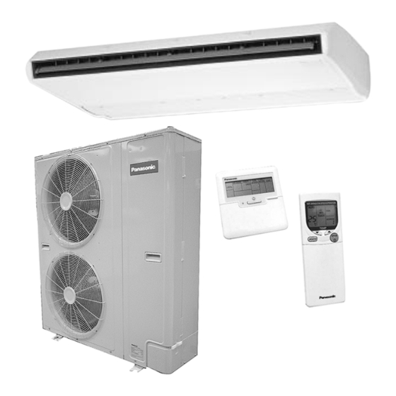
CS-W50BTP CU-V50BBP8
CS-W50BTP CU-W50BBP8
Page
3
4
9
10
11
13
25
27
28
29
31
32
© 2002 Matsushita Industrial Corporation. Sdn. Bhd.
(11969-T). All rights reserved. Unauthorized copying
and distribution is a violation of law.
ORDER NO. MAC0210059C2
AIR CONDITIONER
Page
33
34
35
38
39
40
42
47
48
52
53
54
Advertisement
Table of Contents

Related Manuals for Panasonic CS-W50BTP


Summary of Contents for Panasonic CS-W50BTP
-
Page 1: Table Of Contents
ORDER NO. MAC0210059C2 AIR CONDITIONER CS-W50BTP CU-V50BBP8 CS-W50BTP CU-W50BBP8 CONTENTS Page Page 1 SERVICE INFORMATION 13 SAFETY DEVICE 2 FEATURES 14 COMPONENT SPECIFICATION 3 SPECIFICATION (HEAT PUMP TYPE ) 15 CAPACITY AND POWER CONSUMPTION 4 SPECIFICATION (COOLING ONLY TYPE ) - Page 2 25 EMERGENCY OPERATION 29 INSTALLATION (INDOOR UNIT) 26 CONTROL 30 INSTALLATION (OUTDOOR UNIT) 27 WIRED REMOTE CONTROL INSTALLATION MANUAL 31 REPLACEMENT PARTS 28 WIRELESS REMOTE CONTROL INSTALLATION MANUAL...
-
Page 3: Service Information
1 SERVICE INFORMATION Caution: Pb free solder has a higher melting point than standard solder; Typically the melting point is 50 - 70°F (30 - 40°C) higher. Please use a high temperature soldering iron. In case of the soldering iron with temperature control, please set it to 700 ± 20°F (370 ± 10°C). Pb free solder will tend to splash when heated too high (about 1100°... -
Page 4: Features
2 FEATURES 2.1. New design 3. Adoption of wing-shaped vanes 2.1.1. Gentle curved styling • • • • The base has gentle curves which express a functional beauty. It spreads the air quietly over a wide area. • • • • The vanes of the fan have been changed to “aerodynamic”... - Page 5 2.3. Easy installation 2.5. Easy maintenance 2.3.1. Easy suspension 2.5.1. Long life filter (standard equipment) • • • • A suspension bolt fixing bracket with 4-point support is attached to the main unit, which increases the space • • • • In general office environments, cleaning (maintenance) is available for installation.
-
Page 6: Product Features
2.9. Low-noise outdoor units 2.9.1. Product features 2.10. Greatly improved workability increases system renewal • • • • Low-noise design improves comfort in surrounding areas capability 1. The noise-suppressing winglet fan is a result of new research into vane design theory. The unique curved shape suppresses the generation of vortexes, thus reducing air flow noise. - Page 7 2.11. A brand-new control method using the latest in technology • • • • Easier power supply wiring connection Power supply wiring and other wiring tasks can be carried out more easily. − − − − Twin non-polar wires used to connect indoor and outdoor units.
-
Page 8: Wired Remote Control
2.12. Wired Remote Control 2.13. Wireless Remote Control • • • • The new design includes an easily-visible red pilot lamp. The power can be turned on and off at a single touch, without opening the cover. • • • • Has a built-in thermistor, allowing indoor temperature detection in accordance with indoor conditions by switching with main unit thermistor. -
Page 9: Specification (Heat Pump Type )
3 SPECIFICATION (HEAT PUMP TYPE ) CS-W50BTP / CU-W50BBP8 ITEM / MODEL Indoor Unit Outdoor unit Main Body CS-W50BTP CU-W50BBP8 Remote CZ-RD51P (Wired) Control CZ-RL51P (Wireless) Cooling Capacity 14.0 BTU/h 47,700 Heating Capacity 16.0 BTU/h 54,600 Refrigerant Charge-less Standard Air Volume for High Speed... -
Page 10: Specification (Cooling Only Type )
4 SPECIFICATION (COOLING ONLY TYPE ) CS-W50BTP / CU-V50BBP8 ITEM / MODEL Indoor Unit Outdoor unit Main Body CS-W50BTP CU-V50BBP8 Remote CZ-RD51P (Wired) Control CZ-RL01P (Wireless) Cooling Capacity 14.0 BTU/h 47,700 Refrigerant Charge-less Standard Air Volume for High Speed /min... -
Page 11: Technical Drawing
5 TECHNICAL DRAWING... -
Page 13: Circuit Diagram
6 CIRCUIT DIAGRAM... -
Page 25: Operating Instruction
7 OPERATING INSTRUCTION 7.1. Wired Remote Control (OPTIONAL PARTS) NOTES: • • • • Ensure that the correct button is pressed as simultaneous pressing of the multiple buttons will not make the setting correct. • • • • The illustration above is for explanatory purposes only. The appearance will be different during actual operation. •... - Page 26 7.2. Wireless Remote Control (OPTIONAL PARTS) NOTES: • • • • Ensure that the correct button is pressed as simultaneous pressing of the multiple buttons will not make the setting correct. • • • • The illustration above is for explanatory purpose only. The appearance will be different during actual operation. •...
-
Page 27: Refrigeration Cycle
8 REFRIGERATION CYCLE CS-W50BTP/CU-W50BBP8 CS-W50BTP/CU-V50BBP8... -
Page 28: Operation Range
9 OPERATION RANGE Power Supply The applicable voltage range for each unit is given in the following table. The working voltage among the three phases must be balanced within a 3% deviation from each voltage at the compressor terminals. The starting voltage must be higher than 85% of the rated voltage. -
Page 29: Pipe Length
10 PIPE LENGTH CORRECTION OF COOLING CAPACITY AND HEATING CAPACITIES Correction of cooling and heating capacities according to the connecting pipe length. The data of cooling capacities (marked on the name plate) are based on 7.5 meters connecting pipe and horizontal installation. For other pipe length of other installation multiply by the following correction factor to determine the revised cooling capacity. - Page 30 REFRIGERANT ADDITIONAL CHARGE 1. Piping installation by standard piping • • • • At the time of shipment from the factory, this unit is charged with enough refrigerant for an equivalent pipe length of 30m. (Refer to the following table) But when the piping length exceeds 30m, additional charge is required according to the following table.
-
Page 31: Operating Characteristic
IPT (kW) R.C. R.C. F.C.(A) IPT(kW) (Hz) Cool/Heat Cool/Heat (kW) (kW) Cool/Heat Cool/Heat HEAT CS-W50BTP 8.62 / 8.62 4.97 / 5.07 0.74 0.16 0.99 0.22 9.20 / 9.20 5.35 / 5.45 PUMP CU-W50BBP8 8.62 / 8.62 4.95 / 5.05 0.73 0.17... -
Page 32: Fan Performance
12 FAN PERFORMANCE... -
Page 33: Safety Device
13 SAFETY DEVICE INDOOR UNIT Heat pump model Indoor unit CS-W50BTP Cooling only model For Fan Motor Protection, °C Internal Protector (49F) °C For Control Protection, Fuse 3.15 OUTDOOR UNIT Outdoor Unit Heat pump model 50Hz CU- W50BBP8 Cooling 50Hz... -
Page 34: Component Specification
Piston Displacement 16.18 Motor Type Starting Method Direct on-line Starting Rated Output Poles Insulation Class Type MMMAPOE Charge Evaporator Models CS-W50BTP Tube Material Copper tube Outer Diameter Thickness 0.27 No. of Tubes/Row Fin Material Aluminium Thickness 0.105 Fin Pitch NO./inch... -
Page 35: Capacity And Power Consumption
15 CAPACITY AND POWER CONSUMPTION 15.1. HEATING PERFORMANCE Model Heating capacities are based on conditions below. CS-W50BTP 3 phase, 50Hz, 400V Indoor temperature 20°C D.B.T. CU-W50BBP8 Outdoor temperature 7°C D.B. 6°C W.B.T. Heating capacity 14.0 kW Standard air volume 35m... -
Page 36: Cooling Performance
15.2. COOLING PERFORMANCE CS-W50BTP Model Cooling capacities are based on conditions below. CS-W50BTP Cooling 1 phase, 50Hz, 230V capacity 14.0 kW Indoor temperature 27°C D.B.T. 19°C W.B.T. Outdoor temperature 35°C D.B.T. Standard air volume 35m /min Cooling capacity Indoor Outdoor Temperature (°C D.B.T.) Temperature D.B. - Page 37 TC = Total Cooling Capacity IPT = Power Consumption...
-
Page 38: Discharge And Suction Pressure
16 DISCHARGE AND SUCTION PRESSURE... -
Page 39: Reaching Distance
17 REACHING DISTANCE... -
Page 40: Sound Data
18 SOUND DATA... -
Page 42: Twin And Triple
19 TWIN AND TRIPLE • • • • Master unit and slave-units can be set automatically in twin 19.1. Twin and Triple Operation and triple systems. No address setting is necessary. • • • • Simultaneous air conditioning of wide spaces and corners is •... - Page 43 Turn on the power supply. 19.1.2. Automatic address setting for twin Operation: The unit will operate as slave unit 1. and triple systems Automatic address setting is not carried out at this time. Procedure: Turn on the power supply for the indoor and outdoor units.
-
Page 44: Piping Connections
• • • • The indoor units will not run for approximately 1 minute • • • • Do not turn off the power supply for at least 1 minute after while automatic twin/triple address resetting is being carried automatic twin/triple address resetting has been carried out. out. -
Page 45: Refrigerant Charging
19.3. Refrigerant charging • • • • For twin and triple-type systems The pipe length is the total of the branch pipe (L) and the junction pipes (la → lb → lc in order from the thickest diameter). At the point where the pipe length exceeds 30 m, determine the amount of refrigerant for the remaining liquid-side pipe diameters and pipe lengths from the following table in order to charge the system. - Page 46 19.4. Wiring...
-
Page 47: Wiring Mistake Prevention
20 WIRING MISTAKE PREVENTION Improved quality of installation work through adoption of an “Connection error prevention” circuit which prevents wiring mistakes Connection errors with the control wires and the power supply wires will not only contribute to burning-out of the control circuit board, but can also cause large-scale working losses and affect reliability. -
Page 48: Test Operation And Self Diagnosis
21 TEST OPERATION AND SELF DIAGNOSIS 21.1. Test operation 21.3. Test operation using the wired • • • • Always use a properly-insulated tool to operate the switch remote control on the circuit board. (Do not use your finger or any metallic object). - Page 49 21.4. Test operation using the wireless remote control <Air conditioner No.> − − − − The air conditioner No. “01” appears during normal installation and use. When using group control, a different number may appear. The air conditioner No. can be displayed by pressing the air conditioner No. button.
- Page 50 How to display the past error message An error code from 1F15 to 1F49 will be displayed. (The temperature setting display will also change to show the If the “CHECK” display on the wired remote control is not air conditioner No.) flashing, press the CHECK button continuously for 5 seconds or more to display the problem details for the last problem or the problem before that.
-
Page 52: Setting Of Save Energy And Thermistor Switch
22 SETTING OF SAVE ENERGY AND THERMISTOR SWITCH 22.1. Energy save setting 22.2. Switching to the remote • • • • Upper and lower limit can be set for the setting temperature control thermistor during cooling and heating operation. (The factory shipment •... -
Page 53: Group Control
23 GROUP CONTROL Setting group for 1 remote control unit be determined automatically after approximately 1 minute. • • • • When using a remote control thermostat, the thermostat (DIP switch settings are not necessary.) NOTE: setting is used for all indoor units in the group. •... -
Page 54: Troubleshooting
24 TROUBLESHOOTING If test operation does not proceed correctly NOTE: Indoor unit... LED1 on printed circuit board stays Carry out test operation after approximately 12 hours have passed illuminated since the power was turned on (crankcase heater is energized). If operation is started by using the remote control within 1 minute of Outdoor unit... - Page 55 1. The main power is turned on while the transmission connection cord is not connected (open circuit at section wires between the indoor unit(s) are not connected (open circuit at section A) Symptom: Symptom: − − − − Remote control unit.. . Display of “No power supply” Nothing abnormal appears on the remote control −...
- Page 56 Symptom: 1. The main power is turned on while the transmission wires between the indoor unit and the outdoor unit are Nothing abnormal appears on the remote control not connected (open circuit at section A) display, and operation of indoor unit. No. 1 and indoor Symptom: unit No.
- Page 57 1. Automatic address setting (don’t need to set dip-switch) Reset the address by following the procedure: If the wiring is connected properly as above example, the a. After making sure that dip-switches No. 1 to 4 and No. address is set automatically by the main power supply. An 8 are OFF, stop the operation.
- Page 58 Procedures of deleting memory for twin/triple control system 1. Switch off the main power supply. 2. Set the No. 8 pin of dip switch (DSW1) at the indoor unit’s P.C. board to “ON” position. 3. Switch on the main power supply for a minute and then turn it off.
-
Page 59: Emergency Operation
25 EMERGENCY OPERATION Emergency operation Thermistor Cooling mode Heating mode • • • • Emergency operation of outdoor unit Indoor unit Room temperature Fixed at 25°C Pipe temperature Shorted Open Emergency operation can be carried out by setting the DSW1 switch on the printed circuit board of the outdoor Thermistor Cooling mode Heating mode unit to the EMERGENCY position. -
Page 60: Control
26 CONTROL Description of basic Functions 26.1. Cooling mode operation time chart (*1) Outdoor unit fan start control during cooling At the start of cooling mode and drying mode operation, the outdoor unit heat exchanger outlet temperature is detected in order to set the fan speed. - Page 61 26.2. Freezing prevention control 1. Operation During cooling mode operation, after 9 minutes have passed since the compressor turned on, the outdoor unit will stop its operation when the temperature detected by the indoor unit pipe temperature sensor is 2°C or lower. The indoor unit continues operating at the fan speed set by the remote control.
- Page 62 (*2) Outdoor unit fan control during heating mode operation When the compressor is on during heating mode operation (except during defrosting and when the liquid bypass valve is on), the outdoor unit fan is controlled by means of input (CN2) indicating whether the contact of the heating pressure switch on the outdoor unit circuit board is open or closed.
- Page 63 <When hot start operation is cancelled by time> 2. When defrosting is completed a. Start Hot start control commences when defrosting is completed. b. Operation “PREHEAT” appears on the remote control display. (Other displays remain unchanged) The indoor unit fan stops. In addition, during hot starting, the louvre stays at the horizontal position (angle 0°C). c.
- Page 64 <When hot start operation is cancelled by time> 26.5. Indoor unit fan control when thermostat is off during heating mode operation When the thermostat of the indoor unit turns off during heating mode operation, the indoor unit fan operates for 2 minutes at LOW and then stops.
- Page 65 26.7. Defrost mode operation time chart 1. Start and completion of defrosting a. Start During heating mode operation (including automatic heating), after the 45 minutes of defrosting cycle time has passed, defrosting starts if the temperature detected by the outdoor unit heat exchanger outlet sensor is 2°C or lower continuously for 5 minutes.
- Page 66 NOTE: If the remote control display setting temperature (To) is 29°C or higher, the heating thermostat turns on when the room temperature is 31°C. 2. Thermostat characteristics during dry mode. During dry mode operation, cooling mode operation is carried out in accordance with the indoor temperature as shown in the table below.
- Page 67 c. Thermostat characteristics during cooling mode and heating operation The thermostat on/off characteristics in both operation modes are given in the table below.
-
Page 68: Indoor Unit Fan Control
26.9. Indoor unit fan control 1. Fixing at LO, MED or HI When LO, MED or HI is set, the relay switches and operation is carried out at that setting. 2. Automatic fan speed When set to AUTO, the indoor unit fan operation changes as shown in the table below. (Indoor temperature) - (Setting temperature) (Units: K) Mode / Fan Speed Cooling... -
Page 69: Discharge Temperature Control
26.12. Outdoor unit fan excess heat dissipation control 1. When the operation is stopped while the compressor is in operation, the outdoor fan will run at SUPER HI fan speed for approximately 60 seconds and then stops. 26.13. Discharge temperature control 1. -
Page 70: Wired Remote Control Installation Manual
27 WIRED REMOTE CONTROL INSTALLATION MANUAL... - Page 75 28 WIRELESS REMOTE CONTROL INSTALLATION MANUAL...
-
Page 82: Installation (Indoor Unit)
29 INSTALLATION (INDOOR UNIT) -
Page 92: Installation (Outdoor Unit)
30 INSTALLATION (OUTDOOR UNIT) -
Page 104: Replacement Parts
31 REPLACEMENT PARTS 31.1. INDOOR UNIT... - Page 107 PART DESCRIPTION CS-W50BTP CABINET TOP PLATE CWE001016 CABINET FRONT PLATE CWG07K1008 CABINET SIDE PLATE (L) CWD63K1003 VANE SUPPORTER (L) CWG071144 CATCHER CWH601005 CABINET SIDE PLATE (R) CWD63K1003 VANE SUPPORTER (R) CWG071144 BLOWER WHEEL BASE ASS’Y CWD90K1008 BRACKET FAN MOTOR ASS’Y...
- Page 108 All parts are supplied from MAICO, Malaysia (Vendor Code: 061)
- Page 109 31.2. OUTDOOR UNIT...
- Page 113 CU-W50BBP8 PART DESCRIPTION QTY. CU-W50BBP8 BASE PAN ASS’Y CWD52K1040A COMPRESSOR ZR68KCE-TFD ANTI-VIBRATION BUSHING CWH501020 NUT FOR COMP. MOUNT. CWH4582065 CRANKCASE HEATER CWA341002 CONDENSER COMPLETE CWB32C1286 TUBE ASS’Y (CAPILLARY TUBE) CWT07K1109 PIPE HOLDER RUBBER CWG251021 CONDENSER SIDE PLATE CWD911123 CONDENSER TOP PLATE CWD911133 TUBE ASS’Y(PRESSURE SWITCH) CWT022869...
- Page 114 CU-V50BBP8 PART DESCRIPTION QTY. CU-V50BBP8 BASE PAN ASS’Y CWD52K1040A COMPRESSOR ZR68KCE-TFD ANTI-VIBRATION BUSHING CWH501020 NUT FOR COMP. MOUNT. CWH4582065 CRANKCASE HEATER CWA341002 CONDENSER COMPLETE CWB32C1192 TUBE ASS’Y(CAPILLARY TUBE) CWT07K1080 PIPE HOLDER RUBBER CWG251021 PIPE HOLDER RUBBER CWG251015 CONDENSER SIDE PLATE CWD911123 CONDENSER TOP PLATE CWD911133...