Table of Contents
Advertisement
OPERATOR'S MANUAL
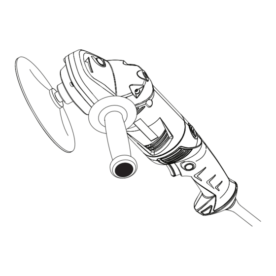
6 in. RIGHT ANGLE SANDER/POLISHER
DOUBLE INSULATED
Model No.
315.115060
:
WARNING
To reduce the risk of injury,
the user must read and understand the
operator's manual before using this product.
Customer Help Line: 1-800-932-3188
Sears, Roebuck and Co., 3333 Beverly Rd., Hoffman Estates, IL 60179 USA
Visit the Craftsman web page: www.sears.com/craftsman
983000-859
1-03-06 (REV:00)
Save this manual for future reference
1
Advertisement
Table of Contents

Related Manuals for Craftsman 315.115060


Summary of Contents for Craftsman 315.115060
- Page 1 Customer Help Line: 1-800-932-3188 Sears, Roebuck and Co., 3333 Beverly Rd., Hoffman Estates, IL 60179 USA Visit the Craftsman web page: www.sears.com/craftsman Save this manual for future reference 983000-859 1-03-06 (REV:00)
-
Page 2: Table Of Contents
If this Craftsman tool fails to give complete satisfaction within one year from date of purchase, RETURN IT TO ANY SEARS STORE OR OTHER CRAFTSMAN OUTLET IN THE UNITED STATES FOR FREE REPLACEMENT. If this Craftsman tool is used for commercial or rental purposes, this warranty applies for only 90 days from the date of purchase. -
Page 3: General Safety Rules
GENERAL SAFETY RULES Avoid accidental starting. Be sure switch is off before WARNING: Read and understand all instruc- plugging in. Carrying tools with your finger on the switch tions. Failure to follow all instructions listed below, or plugging in tools that have the switch on invites may result in electric shock, fire and/or serious accidents. -
Page 4: Specific Safety Rules
GENERAL SAFETY RULES SERVICE When servicing a tool, use only identical replace- ment parts. Follow instructions in the Maintenance Tool service must be performed only by qualified section of this manual. Use of unauthorized parts or repair personnel. Service or maintenance performed failure to follow Maintenance Instructions may create a by unqualified personnel may result in a risk of injury. -
Page 5: Symbols
SYMBOLS Some of the following symbols may be used on this tool. Please study them and learn their meaning. Proper inter- pretation of these symbols will allow you to operate the tool better and safer. SYMBOL NAME DESIGNATION/EXPLANATION Volts Voltage Amperes Current Hertz... -
Page 6: Symbols
SYMBOLS The following signal words and meanings are intended to explain the levels of risk associated with this product. SYMBOL SIGNAL MEANING Indicates an imminently hazardous situation, which, if not avoided, will result DANGER: in death or serious injury. Indicates a potentially hazardous situation, which, if not avoided, could result WARNING: in death or serious injury. -
Page 7: Electrical
ELECTRICAL DOUBLE INSULATION EXTENSION CORDS Double insulation is a concept in safety in electric power When using a power tool at a considerable distance from tools, which eliminates the need for the usual three-wire a power source, be sure to use an extension cord that has grounded power cord. -
Page 8: Features
FEATURES PRODUCT SPECIFICATIONS Disc Size/Polishing Bonnet ......... 6 in. No Load Speed ....... 1,400/min. and 1, 650/min. Speed Switch ............2 Speed Input ........120 V, 60 Hz, AC only, 4.5 Amps Spindle Size ............. 1/2-20 UNF LOCK-ON 90˚ ROTATING BUTTON HANDLE SPINDLE LOCK LIVE... -
Page 9: Assembly
FEATURES UNPACKING WARNING: Do not connect to power supply until This product has been shipped completely assembled. assembly is complete. Failure to comply could result Carefully remove the tool and any accessories from the in accidental starting and possible serious injury. box. - Page 10 OPERATION TWO-SPEED SWITCH TRIGGER See Figure 3. The sander/polisher is equipped with a two-speed switch trigger located in the handle. To turn ON, depress switch trigger. to turn OFF, release switch trigger. For low speed sanding or polishing, depress switch trigger halfway. For high speed sanding or polishing depress switch trigger all the way.
- Page 11 OPERATION SPINDLE LOCK To remove: Unplug the sander/polisher. See Figure 6. Position the tool as shown in figure 6 and lock the Unplug the sander/polisher. spindle lock. To lock the spindle, depress and hold the spindle lock. ...
- Page 12 OPERATION INSTALLING/REMOVING POLISHING BONNET NOTE: Some polishes should be buffed while damp while others must be allowed to dry; therefore, always check the See Figure 8. manufacturer’s label. Unplug the sander/polisher. Tilt the tool so that the polishing bonnet is at a slight angle ...
- Page 13 OPERATION WARNING: To prevent loss of control and possible serious personal injury, always operate the tool with both hands, keeping one hand on the side handle. SANDING See Figure 10. Clamp or otherwise secure the work to prevent it from moving under your sander/polisher.
-
Page 14: Maintenance
WARNING When servicing, use only identical spackling compounds, or plaster are subject to Craftsman replacement parts. Use of any other parts accelerated wear and possible premature failure because may create a hazard or cause product damage. the fiberglass chips and grindings are highly abrasive to bearings, brushes, commutators, etc. -
Page 15: Exploded View And Parts List
CRAFTSMAN SANDER/POLISHER – MODEL NUMBER 315.115060 The model number will be found on a plate attached to the motor housing. Always mention the model number in all correspondence regarding your SANDER/POLISHER or when ordering repair parts. SEE BACK PAGE FOR PARTS ORDERING INSTRUCTIONS... -
Page 16: Purchase
Get it fixed, at your home or ours! Your Home For repair – in your home – of all major brand appliances, lawn and garden equipment, or heating and cooling systems, no matter who made it, no matter who sold it! For the replacement parts, accessories and owner’s manuals that you need to do-it-yourself.