Table of Contents
Advertisement
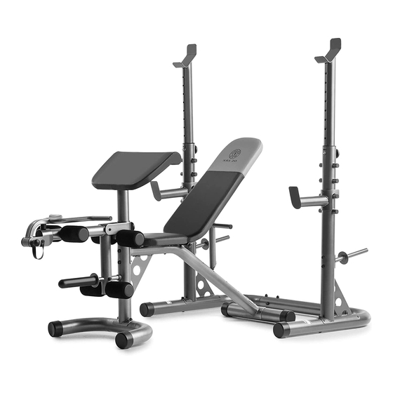
Model No. GGBE1486.2
Serial No.
Write the serial number in the
space above for future reference.
Serial Number Decal (Under Seat)
QUESTIONS?
As a manufacturer, we are com-
mitted to providing complete
customer satisfaction. If you
have questions, or if a part is
damaged or missing, PLEASE
CONTACT OUR CUSTOMER
SERVICE DEPARTMENT
DIRECTLY.
CALL TOLL-FREE:
1-877-776-4777
Mon.–Fri., 6 a.m.–6 p.m. MST
Sat. 8 a.m.-4 p.m. MST
ON THE WEB:
www.goldsgympowerflex.com
CAUTION
Read all precautions and instruc-
tions in this manual before using
this equipment. Save this manu-
al for future reference.
USER'S MANUAL
Advertisement
Table of Contents

Related Manuals for Gold's Gym XRS 20


Summary of Contents for Gold's Gym XRS 20
- Page 1 Model No. GGBE1486.2 Serial No. Write the serial number in the space above for future reference. USER’S MANUAL Serial Number Decal (Under Seat) QUESTIONS? As a manufacturer, we are com- mitted to providing complete customer satisfaction. If you have questions, or if a part is damaged or missing, PLEASE CONTACT OUR CUSTOMER SERVICE DEPARTMENT...
-
Page 2: Table Of Contents
Apply the decals in the location shown. Note: The decals may not be shown at actual size. GOLD'S GYM is a registered trademark of Gold's Gym International, Inc. This product is manufactured and distributed under license from Gold's Gym International, Inc. -
Page 3: Important Precautions
IMPORTANT PRECAUTIONS WARNING: To reduce the risk of serious injury, read all important precautions and instructions in this manual and all warnings on the weight bench before using the weight bench. before using the weight bench. ICON assumes no responsibility for personal injury or property dam- age sustained by or through the use of the weight bench. -
Page 4: Before You Begin
Thank you for selecting the versatile GOLD’S GYM ® manual. To help us assist you, note the product model XRS 20 weight bench. The weight bench offers a number and serial number before contacting us. The selection of exercise stations designed to develop the model number and the location of the serial number major muscle groups of the body. -
Page 5: Part Identification Chart
PART IDENTIFICATION CHART See the drawings below to identify small parts used in assembly. The number in parentheses by each drawing is the key number of the part, from the PART LIST on page 17. Note: Some small parts may have been pre- attached. -
Page 6: Assembly
ASSEMBLY Make Assembly Easier • Tighten all parts as you assemble them, unless instructed to do otherwise. Everything in this manual is designed to ensure that the weight bench can be assembled suc- • As you assemble the weight bench, make sure all cessfully by almost anyone. - Page 7 2. Attach the Rear Stabilizer (3) to the Frame (1) with two M10 x 90mm Carriage Bolts (40) and two M10 Nylon Locknuts (57). Do not tighten the Nylon Locknuts yet. Warning Decals 3. Attach the Seat (18) and the Seat Bracket (59) to the Frame (1) with two M6 x 80mm Screws Wide End (46) and two M6 Washers (53).
- Page 8 5. Apply a portion of the included grease to an M10 x 170mm Bolt (49). Attach the Backrest Post (15) to the Backrest Frames (16) with the Bolt, two M10 Washers (52), and an M10 Nylon Locknut (57). Do not tighten the Nylon Wide End Locknut yet.
- Page 9 8. Insert the Long Pad Tube (36) into the bracket on the Front Leg (4). Slide two Foam Pads (22) onto the Pad Tube, and press two Pad Caps (23) into the ends of the Foam Pads. Repeat this step with the two Short Pad Tubes (21) and the Leg Lever (5).
-
Page 10: M10 X 90Mm Carriage
11. Attach a Foot (39) to the Left Upright Base (9) with an M5 x 16mm Screw (50). Insert an M10 x 90mm Carriage Bolt (40) up into the Left Upright Base. Attach the Left Upright Base (9) to the Base (7) with two M10 x 90mm Carriage Bolts (40), an M10 x 95mm Bolt (42), four M10 Washers (52), and three M10 Nylon Locknuts (57). -
Page 11: Adjustment
ADJUSTMENT This section explains how to adjust the weight bench. See the EXERCISE GUIDELINES on page 13 for impor- tant information about how to get the most benefit from your exercise program. Also, refer to the accompanying exercise guide to see the correct form for each exercise. Make sure all parts are properly tightened each time you use the weight bench. - Page 12 REMOVING THE CURL BAR When performing exercises that do not require the Curl Bar (17), pull the Curl Bar Pin (33) out of the Leg Lever (5) and remove the Curl Bar. When attaching the Curl Bar (17), insert the Curl Bar Pin (33) completely through the Leg Lever (5).
-
Page 13: Exercise Guidelines
EXERCISE GUIDELINES THE FOUR BASIC TYPES OF WORKOUTS PERSONALIZING YOUR EXERCISE PROGRAM Muscle Building Determining the exact length of time for each workout, To increase the size and strength of your muscles, as well as the number of repetitions or sets completed, push them close to their maximum capacity. - Page 14 Rest for a short period of time after each set. The slowly as you stretch and do not bounce. Ease into ideal resting periods follow: each stretch gradually and go only as far as you can • Rest for three minutes after each set for a muscle without strain.
- Page 15 EXERCISE WEIGHT SETS REPS MONDAY Date: AEROBIC EXERCISE TUESDAY Date: EXERCISE WEIGHT SETS REPS WEDNESDAY Date: THURSDAY AEROBIC EXERCISE Date: EXERCISE WEIGHT SETS REPS FRIDAY Date: Make photocopies of this page for scheduling and recording your workouts.
- Page 16 EXERCISE WEIGHT SETS REPS MONDAY Date: AEROBIC EXERCISE TUESDAY Date: EXERCISE WEIGHT SETS REPS WEDNESDAY Date: THURSDAY AEROBIC EXERCISE Date: EXERCISE WEIGHT SETS REPS FRIDAY Date: Make photocopies of this page for scheduling and recording your workouts.
-
Page 17: Part List
PART LIST—Model No. GGBE1486.2 R0507A Key No. Qty. Description Key No. Qty. Description Frame Tether Front Stabilizer Adjustment Knob Rear Stabilizer Long Pad Tube Front Leg Upright Bushing Leg Lever Upright Spacer Curl Post Foot Base M10 x 90mm Carriage Bolt Olympic Adapter Weight Clip Left Upright Base... -
Page 18: Exploded Drawing
EXPLODED DRAWING—Model No. GGBE1486.2 R0507A... - Page 19 EXPLODED DRAWING—Model No. GGBE1486.2 R0507A...
-
Page 20: Ordering Replacement Parts
ORDERING REPLACEMENT PARTS To order replacement parts, please see the front cover of this manual. To help us assist you, be prepared to pro- vide the following information when contacting us: • the model number and serial number of the product (see the front cover of the manual) •...