Table of Contents
Advertisement
Quick Links
SERVICE MANUAL
Ver 1.0 2003. 03
Time display:
24-hour system
Frequency range
Band
SRF-M37
FM
87.5-108 MHz
530-1 710 kHz
AM
531-1 710 kHz
Battery Life (Approx. hours)
When using
FM
Sony alkaline
35
LR 03 (size AAA)
Sony R03 (size AAA)
14
* Measured by JEITA (Japan Electronics and Information Technology
Industries Association) standards. The actual battery life may vary
depending on the circumstance of the unit.
Sony Corporation
9-877-168-01
2003C167800-1
Personal Audio Company
© 2003.03
Published by Sony Engineering Corporation
SPECIFICATIONS
Output
Power output
Channel step
0.1 MHz
Power requirements
10 kHz
9 kHz
Dimensions
(JEITA*)
AM
MW/LW
52
52
Mass
21
21
Accessories Supplied
Stereo headphones (1): North American model
Stereo earphones (1): Other models
Belt Clip (1)
Design and specifications are subject to change without notice.
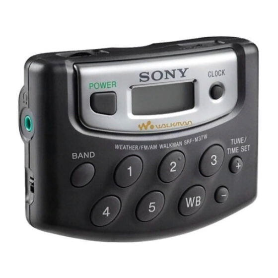
FM STEREO/AM PLL SYNTHESIZED RADIO
SRF-M37
i jack (ø 3.5 mm, stereo minijack) load impedance 24 Ω (North
American model), 16 Ω (Other models)
2.8 mW + 2.8 mW (at 10 % harmonic distortion)
1.5 V DC, one R03 (size AAA) battery
Approx. 83 × 63 × 32 mm (w/h/d)
× 2
× 1
(3
3
/
1
/
5
/
inches) incl. projecting parts and controls
8
2
16
Approx. 83 × 63 × 25 mm (w/h/d)
× 2
× 1 inches) not incl. projecting parts and controls
(3
3
/
1
/
8
2
Approx. 94 g (3.32 oz.) incl. battery and belt clip.
E Model
Advertisement
Table of Contents

Related Manuals for Sony SRF-M37


Summary of Contents for Sony SRF-M37
- Page 1 Stereo earphones (1): Other models Belt Clip (1) Design and specifications are subject to change without notice. FM STEREO/AM PLL SYNTHESIZED RADIO Sony Corporation 9-877-168-01 2003C167800-1 Personal Audio Company © 2003.03 Published by Sony Engineering Corporation...
-
Page 2: Section 1 General
SRF-M37 SECTION 1 This section is extracted from instruction manual. GENERAL Setting the Clock The display will flash “AM 12:00” or “0:00” when the battery is first inserted. Hold down CLOCK for more than 2 seconds. The beep sounds and the hour flashes in the display. -
Page 3: Section 2 Disassembly
SRF-M37 SECTION 2 DISASSEMBLY • This set can be disassembled in the order shown below. CABINET (FRONT) ASSY KEY BOARD ASSY MAIN BOARD ASSY Note : Follow the disassembly procedure in the numerical order given. 2-1. Cabinet (Front) Assy 3 cabinet (front) assy 2 four tapping screws (B 1.7 ×... - Page 4 SRF-M37 2-2. KEY Board Assy 1 Remove the soldering from two points. 2 Remove the soldering 6 KEY board assy from the eleven points. 5 battery terminal (+) 4 battery terminal (-) 3 two hooks 2-3. MAIN Board Assy 3 two wire 1 two tapping screws (B 1.7 ×...
-
Page 5: Section 3 Adjustments
SRF-M37 SECTION 3 ADJUSTMENTS AM Section AM FREQUENCY COVERAGE ADJUSTMENT Setting: Adjust for a reading on digital voltmeter. BAND switch: AM 1.3V ± 0.1V 530 kHz Connection: 8.1V ± 0.3V Confirm 1,710 kHz For AM frequency coverage adjustment and FM frequency coverage check. - Page 6 SRF-M37 SECTION 4 DIAGRAMS Note on Schematic Diagram: Note on Printed Wiring Board: • Y : parts extracted from the conductor side. • All capacitors are in µF unless otherwise noted. pF: µµF b : Pattern from the side which enables seeing.
- Page 7 SRF-M37 4-1. Block Diagram FM SENS LOCAL 10.7MHz FRONT-END AUDIO BPF1 IF AMP,DET,FM MPX POWER AMP B.P.F. QUAD RF VCC VCC OUT 2 IN 2 10.7MHz FM MIX FM RF IN FM IF IN LOUT IN 1 OUT 1 FM/AM...
-
Page 8: Main Board
SRF-M37 4-2. Printed Wiring Boards • Semiconductor Location Ref. No. Location KEY BOARD S104 G-11 BAND G-11 F-10 MAIN BOARD FM SENS LOCAL S102 B-10 S103 T101 POWER D101 D102 D103 D104 D105 S105 E-10 TP12 (ANT) C126 IC101 IC102... - Page 9 SRF-M37 4-3. Schematic Diagram • See page 6 for Waveforms. • See page 10 for IC Block Diagrams. JC18 TP10 (VT) DTA114YUA IPS226 1000p KV1610S-TL2 MW FERRITE 1000p ROD ANTENNA 470p DTC144TUA 2SC3931 100p IPS226 1000p BPF1 GFMB7 LA4535M TP13...
- Page 10 SRF-M37 4-4. IC Block Diagrams 4-5. IC Pin Function Description • IC101 TC9329FA-123 (DIGITAL TUNING, SYSTEM CONTROL) IC1 TA2154AFN-EL Pin No. Pin Name Description 1 to 4 COM1 to COM4 LCD common output 5 to 17 S1 to S13 LCD segment output TEST Test mode control signal input (“H”...
-
Page 11: Exploded Views
SRF-M37 SECTION 5 EXPLODED VIEWS NOTE: • -XX, -X mean standardized parts, so they may • The mechanical parts with no reference number have some differences from the original one. in the exploded views are not supplied. • Items marked “*” are not stocked since they are seldom required for routine service. -
Page 12: Section 6 Electrical Parts List
SRF-M37 SECTION 6 ELECTRICAL PARTS LIST NOTE: • Due to standardization, replacements in the • CAPACITORS: • SEMICONDUCTORS parts list may be different from the parts uF: µF In each case, u: µ, for example: specified in the diagrams or the components •... - Page 13 SRF-M37 MAIN Ref. No. Part No. Description Remarks Ref. No. Part No. Description Remarks R113 1-216-845-11 METAL CHIP 100K 1/16W 1-162-970-11 CERAMIC CHIP 0.01uF R114 1-216-821-11 METAL CHIP 1/16W 1-162-970-11 CERAMIC CHIP 0.01uF R115 1-216-821-11 METAL CHIP 1/16W R117 1-216-821-11 METAL CHIP...
- Page 14 SRF-M37 MAIN Ref. No. Part No. Description Remarks Ref. No. Part No. Description Remarks < IC > 1-216-821-11 METAL CHIP 1/16W 1-216-821-11 METAL CHIP 1/16W 6-703-664-01 IC TA2154AFN-EL 1-216-821-11 METAL CHIP 1/16W 6-700-362-01 IC LA4535M-TE-L 1-216-801-11 METAL CHIP 1/16W 1-216-833-11 METAL CHIP 1/16W <...
- Page 15 SRF-M37 MEMO...
-
Page 16: Revision History
SRF-M37 REVISION HISTORY Clicking the version allows you to jump to the revised page. Also, clicking the version at the upper right on the revised page allows you to jump to the next revised page. Ver. Date Description of Revision...