Table of Contents
Advertisement
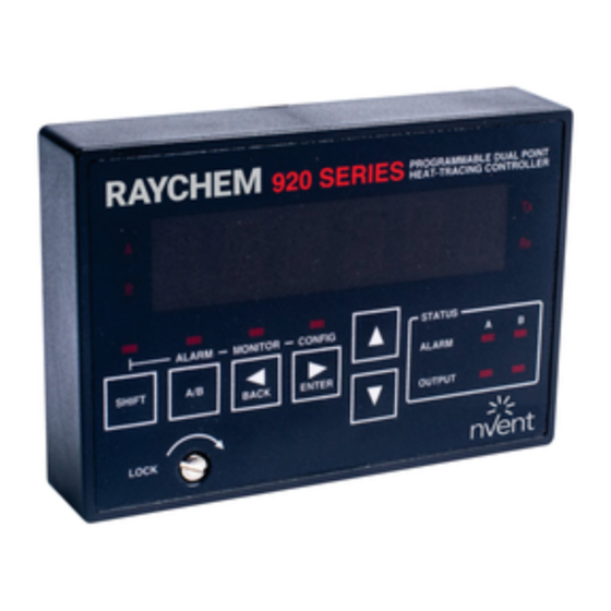
920 Series Heat Trace Controller
InstallatIon, operatIng and MaIntenance InstructIons
INDUSTRIAL HEAT TRACING SOLUTIONS
R a
y c
h e
m
A
9 2
0
B
S E
R I
E S
P R
O G
H E
R A
M M
A T
T R
A B
A C
L E
A L
I N G
D U
S H
A R
A L
C O
I F T
M
N T
P O
R O
I N T
L L E
M O
R
N I T
A / B
O R
C O
T x
N F
L O
I G
B A
C K
C K
R x
E N
T E R
S T
A T
U S
A L
A R
M
O U
T P
U T
EN- Raychem920series-IM-H56874 05/15
Firmware versions # up to V3.2X
R a
y c
h e
m
9 2
0
S E
R I
E S
A L
S H
A R
I F T
M
M O
N I T
A / B
O R
C O
N F
L O
I G
B A
C K
C K
E N
T E
S T
R
A T
U S
A L
A R
M
O U
T P
U T
1 / 82
Advertisement
Table of Contents

Summary of Contents for Pentair 920 Series
- Page 1 920 Series Heat Trace Controller InstallatIon, operatIng and MaIntenance InstructIons Firmware versions # up to V3.2X I N G I F T I N T L L E N I T A / B T E R I F T...
-
Page 2: Table Of Contents
Contents Introduction ..............................4 Certification ............................4 Limited Warranty ..........................4 Warranty Exclusion/Disclaimer ......................4 Exclusive Remedies ..........................4 Conducted and Radiated Emissions—FCC/DOC Statement of Compliance ........4 What’s New ..............................5 New Controller Features ........................5 New Operator Console Features ......................5 Section I –... - Page 3 Appendix E 100 Ω Platinum RTD Table ......................74 Appendix F 100 Ω Nickel-Iron RTD Table .......................75 Appendix G Factory Default/Configuration Sheets ..................76 G.1 Configuration Sheet V3.00 ......................76 G.2 920 Series HTC Configuration Sheet V3.1X and V3.2X..............79 INDUSTRIAL HEAT TRACING SOLUTIONS EN- Raychem920series-IM-H56874 05/15 3 / 82...
-
Page 4: Introduction
Installation and Maintenance Instructions for Firmware Versions up to and Including V3.2X This manual provides information pertaining to the installation, operation, testing, adjustment, and maintenance of the Raychem Model 920 Series Heat Trace Control and Monitoring products. Additional copies of the operating manual may be ordered separately through your Pentair Thermal Managament representative or online at www.thermal.pentair.com using the document... -
Page 5: What's New
What’s neW This section provides a summary of the new features that have been added since the last version of this manual was printed. It is assumed that the reader is already familiar with the earlier versions of the 920 Controller. neW ControLLer features • Alarm filtering is now available for: –... -
Page 6: Section I - Overview
I – overvIeW 1.1 ControLLers Covered by thIs manuaL This document covers the 920 Series of heat trace controllers and available options. The information coincides with the specific releases of firmware for the 920 product which are listed on the cover. As Pentair Thermal Managament releases new firmware to modify or enhance the product significantly, new documentation will accompany these releases. - Page 7 Ground-fault alarm and trip Ground-fault (GF) current levels are monitored and displayed in milliamps. The availability of the actual ground-fault level gives the user the choice of both alarm and trip levels suitable for the particular installation. Using multiple SSRs or a multipole contactor allows all powered legs of non-neutral circuits to be switched off under GF conditions.
-
Page 8: Modular Components
Csa C/us and c-etL-us approved The 920 series of controllers is approved for Class I, Division 2, Groups A,B,C,D and Zone 2 hazardous locations, making it ideal for direct installation in the field. This can save the significant expense of wiring back to a central-ly-located electrical distribution center. -
Page 9: Controller Assemblies
Refer to the Ordering Guide in section 1.5 on page 10 for a sample listing of available configurations. If your application requires a customized solution, please contact your Pentair Thermal Managament representative for help in specifying an assembly suited to your particular requirements. - Page 10 1.5.1 enCLosure assembLy enclosure assemblies description Catalog number part number Weight/lbs raychem 920 controller–2 pt in a 14" x 12" x 8" frp 920*E4FWL*SIS302*SS3102*HTC*CON 10160-010 enclosure with window and quick-release latches, control module, and operator console. 1P 30 A 277 V SSR/pt.
-
Page 11: Section 2 - Installation And Wiring
Pentair Thermal Managament representative. If the shipping container is damaged, or the cushioning material shows signs of stress, notify the carrier as well as your Pentair Thermal Managament representative. Keep the shipping materials for the carrier’s inspection. - Page 12 Do not install or remove the control module while the unit is powered. Fig 2.1 Control module installation The 920 series controller is designed to be mounted to a flat back plate/panel using a terminal board. This plug-in design simplifies installation and maintenance by allowing all of the low- voltage field wiring to remain undisturbed while a control module is installed or removed.
-
Page 13: Wiring
Step “Hinge” the bottom of the console downwards until it is flush with the front of the control module. Fig. 2.3 Console installation – Step 2 Step If the console is to be permanently installed, secure it to the control module using the captive screw provided. - Page 14 temperature sensors terminal no. Point A – Shield Point A TS 1 Source (WHT) Point A TS 1 Sense (WHT) Point A TS 1 Common (RED) Point A – Shield Point A TS 2 Source (WHT) Point A TS 2 Sense (WHT) Point A TS 2 Common (RED) Point B –...
-
Page 15: Power Connections
Communications wiring should use twisted conductor, shielded cable. Shields on communications wiring should be grounded at one end only, using the terminals provided. The following tables define the appropriate signal connections for the various types of interfaces: rs-485 (2-Wire) Connections Communication signal terminal no. -
Page 16: Initial Power-Up
2.7.6 Input poWer The 920 controller may be powered directly from the trace voltage (120 Vac to 277 Vac), through a step-down transformer, or from a sepa-rate circuit. The same wiring terminal assignments are used in all configurations, as defined below: power Connections terminal no. -
Page 17: Setup For The 920
See section 3.5.21 on page 26. 2.9.2 sWItCh ratInG setup (ssr onLy) The 920 series control module is ordered and shipped as a separate item from the enclosure assembly. This prevents Pentair Thermal Managament from predetermining the SWITCH CURRENT RATING settings since various types of output switches are available. -
Page 18: Section 3 - Programming And Configuration
While configuring the controller, it is important to remember that the 920 series controller is a two control point device. Both control points allow completely independent operation and, as such, have their own individual settings that must be configured. -
Page 19: 920 Operator Console Display
920 Operator Console. For a detailed description of each of the console features and operating instructions, refer to the separate Raychem 920 Series HTC Operator Console—Installation and Operating Instructions (Pentair Thermal Managament reference H56903). - Page 20 Any combination of 19 characters from A-Z, 0-9, /, -, ., (,) or #. procedure: Using the 920 Operator Console, enter the desired text. Refer to the separate Raychem 920 Series HTC Operator Console—Installation and Operating Instructions (Pentair Thermal Managament reference H56903) for TAG entry information.
- Page 21 3.5.5 deadband settInG (Deadband control mode only or if a point controls an INHIBIT output signal) purpose: When an HTC equipped with a contactor is used to control a trace circuit, it is necessary to use deadband rather than proportional control. This is done to prevent the contactor from switching on and off rapidly and being worn out prematurely.
- Page 22 range: 0.3 to 100.0 amps (CURRENT TURNS RATIO = 1.00) procedure: Adjust the CIRCUIT BREAKER CURRENT RATING setting to the heating circuit breaker size (i.e. 30.0 amps). Note that the CIRCUIT BREAKER CURRENT RATING setting is affected by the CURRENT TURNS RATIO setting. The absolute maximum adjusted CIRCUIT BREAKER CURRENT RATING setting is 300.0 amps.
- Page 23 3.5.12 temperature sensor ControL mode purpose: The TS CONTROL MODE allows the selection of one of eleven possible temperature control modes for the controller. The different modes allow redundant fail-safe temperature sensing, averaging, or minimum maintain temperature control. setting: Select one of the following eleven possible modes: Control ts and description CONTROL USING TS 1, FAIL OFF/ON CONTROL USING TS 1, FAIL TO TS 2...
- Page 24 3.5.15 ts 1 hIGh LImIt Cutout purpose: When enabled, the TS 1 HIGH LIMIT CUTOUT feature will override the CONTROL SETPOINT temperature and force the controller output off if the TS 1 reading exceeds the HIGH TS 1 ALARM temperature setting. This is a non-latching condition, so once the TS 1 reading drops below the HIGH TS 1 ALARM temperature setting, the controller will resume normal operation.
- Page 25 Important: • If an alternate voltage source is selected, then all voltage alarming features are disabled for this HTC and the VOLTAGE TURNS RATIO is not used. • It is not possible to set both points to use the others’ voltage source. 3.5.20 fIxed voLtaGe settInG (v3.11 and up) (Only if VOLTAGE SOURCE = FIXED) purpose: This parameter specifies the voltage value that the HTC should use when the VOLTAGE SOURCE = FIXED.
- Page 26 Important: • Auto-cycling should always be enabled for normal operation. Disabling this feature should only be required where the HTC system is monitoring a circuit exercised by some other device or means. Although this function defeats temperature control and forces output on, the controller will continue to adjust the output for protection purposes or power limiting (SSR option only). • Auto-cycling is inhibited if the controller is in the load shedding mode. See section 5.3 on page 52.
- Page 27 setting: REMOTE or EXT. INPUT procedure: If the override signal will be generated remotely and received by the HTC via the optional communications interface, select REMOTE as the OVERRIDE SOURCE. If the override signal will be received by the HTC via the external input terminals on the 920 terminal board, select EXTERNAL INPUT as the OVERRIDE SOURCE.
-
Page 28: Common Controller Setup
This is a safety feature to prevent users in the field from modifying the CONTROL SET-POINT temperature setting to a dangerous level. range: –76°F to 1058°F (–60°C to 570°C) procedure: Adjust the CONSOLE SETPOINT MINIMUM temperature value to limit the minimum allowable CONTROL SETPOINT TEMPERATURE that may be set using the optional 920 Operator Console. - Page 29 setting EXTERNAL INPUT to NOT USED or TEMPBUS™ will automatically set OVERRIDE SOURCE to REMOTE. 3.6.4 externaL output port purpose: The EXTERNAL OUTPUT port can be programmed to allow Point A to function as a “master” 920 HTC to control up to 25 “slave” 920 HTC units. A “master” can either force its “slaves”...
-
Page 30: Temperature Alarms
user for input and/or displaying messages and status. setting: ENGLISH or FRANCAIS procedure: Select the language of choice—ENGLISH for English prompts and messages, or FRANCAIS for French prompts and messages. 3.6.8 poInt b used purpose: Allows the second control point (Point B) to be disabled when it is not being used. This is an easy method of disabling all ALARMS, etc. - Page 31 • This alarm must be enabled and its setpoint must be below the CONTROL SETPOINT temperature if fail-safe mode uses the temperature from TS 1. 3.7.3 hIGh temperature sensor 1 aLarm purpose: If enabled, the HIGH TS 1 ALARM allows for alarming of high temperature conditions as sensed by the first temperature sensor (TS 1). alarm mask: ENABLE or DISABLE range: –76°F to 1058°F (–60°C to 570°CF) procedure: Adjust the HIGH TS 1 ALARM temperature setpoint to the desired value.
- Page 32 condition resulting from a forced on failure of the heating circuit should first be alarmed by the SWITCH FAILURE ALARM. See section 3.8.18 on page 40 for more information. 3.7.7 LoW temperature sensor aLarm fILter tIme settInG (v3.11 and up) purpose: The LOW TS ALARM FILTER will prevent LOW TS 1 and/or LOW TS 2 ALARMS from being indicated until their corresponding alarm condition has existed for the duration of the LOW TS ALARM FILTER time.
-
Page 33: Other Alarms
procedure: Enable or disable the alarming of a failure of the designated control temperature sensor as required. Important: This alarm should always be enabled. If the controller experiences a CONTROL TS FAILURE it will turn the output off or on (as spec-ified by TS FAIL MODE) until this alarm is cleared. - Page 34 • If the user resets an alarm while the alarm condition is still exists, the alarm will not be indicated again until the entire alarm filter time has expired. 3.8.3 hIGh Load Current aLarm purpose: Alarms current levels that are higher than a preset limit for the application. alarm mask: ENABLE or DISABLE range: 0.3 to 100.0 amps (CURRENT TURNS RATIO = 1.00) procedure: Adjust the HIGH CURRENT ALARM level to the desired value.
- Page 35 • If the user resets an alarm while the alarm condition is still exists, the alarm will not be indicated again until the entire alarm filter time has expired. 3.8.7 Ground-fauLt trIp aLarm purpose: This value sets the upper limit of allowable ground-fault leakage current. Exceeding this limit will result in the output switch being latched off and the GFI TRIP ALARM activated to indicate a ground fault condition.
- Page 36 adjusted HIGH VOLTAGE ALARM level is 1000 volts. The absolute minimum adjusted HIGH VOLTAGE ALARM level is 1 volt. See section 3.5.21 on page 26 for more information regarding the VOLTAGE TURNS RATIO function. Important: The HIGH VOLTAGE ALARM is only available if VOLTAGE SOURCE is set to the Point being used.
- Page 37 before the corresponding alarm will be indicated. • If the user resets an alarm while the alarm condition is still exists, the alarm will not be indicated again until the entire alarm filter time has expired. 3.8.14 hIGh resIstanCe aLarm purpose: Alarms heater resistance levels that have increased from the NOMINAL RESISTANCE setting by more than the selected amount. The HIGH RESISTANCE ALARM may be used to indicate an open or a high resistance connection or, when using constant-wattage parallel cables, may indicate the failure of one or more heating zones.
- Page 38 before the corresponding alarm will be indicated. • If the user resets an alarm while the alarm condition is still exists, the alarm will not be indicated again until the entire alarm filter time has expired. 3.8.16 nomInaL resIstanCe settInG purpose: This parameter defines the nominal expected heater resistance. A value must be entered by the user to allow the HIGH and LOW RESISTANCE ALARMS to be used. In installations where the power source may experience periodic fluctuations (surges and/or brown-out con- ditions), alarming on resistance deviation offers an improved method of monitoring tracer integrity over simple LOW and HIGH CURRENT ALARMS.
- Page 39 the overcurrent trip limit and the controller will not be able to soft start the trace circuit. If this condition persists, please contact your nearest sales office for recommendations and solutions to this problem. 3.8.18 sWItCh faILure aLarm purpose: The purpose of the SWITCH FAILURE ALARM is to indicate that an output switch failure has occurred.
-
Page 40: Communications Setup
This indicates an internal problem, and the control module should be replaced and returned to Pentair Thermal Managament for repair. - Page 41 The HTCBUS™ protocol must be selected in order to set the HTCBUS™ ADDRESS. Important: A unique HTCBUS™ communications address is always assigned by Pentair Thermal Managament and identified by the label on the front of the 920 control module (see Figure 3.1).
-
Page 42: Baud Rate
same MODBUS™ ADDRESS. This increases the number of HTCs allowed on a single MODBUS™ port from 247 to 7,904 (=247 x 32). This requires that any HTC sharing the same MODBUS™ ADDRESS as another HTC must have its own unique MODBUS™ SUB ADDRESS. 3.9.5 baud rate purpose: Defines the data rate at which communications occur. -
Page 43: Operator Console Functions
The following features are part of the controller’s programming, but are only used in conjunction with the optional 920 Operator Console. For a detailed description of each of the console features and operating instructions, refer to the separate document Raychem 920 Series HTC Operator Console—Installation and Operating Instructions (Pentair Thermal Managament reference H56903) for the particular version of controller firmware that you are using. -
Page 44: Copy Configuration Functions (V3.11 And Up)
3.11.1 Copy defauLts to Common (v3.11 and up) purpose: Loads Pentair Thermal Managament’ default configuration parameters that are common to both Point A and Point B as defined in Appendix G. procedure: Enter the “Copy Configuration Sub-Menu” and select DEFAULTS TO COMMON. - Page 45 Enter the “Copy Configuration Sub-Menu” and select DEFAULTS TO A. 3.11.3 Copy defauLts to poInt b (v3.11 and up) purpose: Loads the point-specific Pentair Thermal Managament default configuration parameters, as defined in Appendix G, for Point B. As well, all of Point B’s maintenance data are reset.
-
Page 46: Section 4 - Monitored Parameters
seCtIon 4 – monItored parameters 4.1 IntroduCtIon The following is a brief summary of each of the measured and calculated parameters the 920 series control module provides to the user. Detailed information regarding settings, alarms limits, etc. may be found in Section 3 on page 18. For detailed information regarding the display of these variables using the 920 Operator Console, Model 780/GCC-9000, Raychem Supervisor or other interface, refer to the ap-propriate user manuals. -
Page 47: Maintenance Data
interface. Important: The controller calculates this parameter using the voltage sensed by the switch interface module and multiplying it by the VOLTAGE TURNS RATIO to yield an adjusted voltage value. 4.2.8 poWer purpose: Load power provides an indication of the average power being consumed by the heat trace cable or the total 3-phase power being consumed by a balanced 3-phase star (“Y”) connected load. - Page 48 a method to do preventative maintenance on the contactor according to the manufacturer’s specifications. The count value is written to the controller’s nonvolatile memory once every 24 hours or whenever any maintenance data is reset by the user. procedure: The CONTACTOR CYCLE COUNTER may be reset to zero using the optional 920 Operator Console or a communicating device. Important: • Once the CONTACTOR CYCLE COUNTER reaches 999,999,999 it stops counting.
-
Page 49: Section 5 - Control Modes
seCtIon 5 – ControL modes 5.1 IntroduCtIon There are several types of control modes in the controller. Some of these modes require further explanation in order to fully understand and implement their operation. This section describes the control modes available in the HTC and how to set their associated parameters. - Page 50 5.2.3 proportIonaL ambIent ssr ControL (for use WIth ssrs onLy) When an HTC using an SSR is used to control the output using the ambient temperature, this control mode should be used. Proportional ambient SSR control on the HTC is implemented as follows: • When using SSRs to directly control the power applied to a heating circuit, the output may be switched on/off very rapidly.
-
Page 51: Load Shedding Control Mode
5.3 Load sheddInG ControL mode Load shedding is a control mode that can be programmed and initiated only by an external communicating device, or by the Model 780/GCC-9000 Group Communications Controller, which overrides temperature control and forces the output of the controller OFF until reset by the 780/ GCC. -
Page 52: Tempbus™ Control Mode
5.4 tempbus™ ControL mode TEMPBUS™ is short for Temperature Bus. This refers to a connection that allows one “master” HTC to share its control temperature with a number of “slave” HTCs. Up to 25 “slave” HTCs can be connected to this bus. Refer to the wiring diagrams in Appendix C for example con-nection details. 5.4.1 tempbus™... -
Page 53: Section 6 - Troubleshooting
6.1.1 GettInG started To access the functions of the 920 Series HTC, use the optional 920 Operator Console. If the modem communications option is installed in the 920 control module, the Model 780/GCC-9000 Group Communications Controller may also be used to access controller parameters. - Page 54 • Verify that the RTD is wired correctly. The heat-tracing controllers will always be terminated in the order: source (WHT), sense (WHT), common (RED). When using the terminal board, these terminals are marked as follows: terminal no. description Point A, Shield Point A, TS 1 Source (WHT) Point A, TS 1 Sense (WHT) Point A, TS 1 Common (RED) Point A, Shield Point A, TS 2 Source (WHT) Point A, TS 2 Sense (WHT)
- Page 55 Ground-fault alarms can be due to incorrect installation as well as leakage resulting from wet system components or faulted cables. The 920 series switch interface detects ground faults by summing the outgoing and return trace currents through an internal current trans-former. Under normal operating conditions (no ground fault condition) this current will be zero.
-
Page 56: Common Alarms-What To Look For
6.3 Common aLarms—What to LooK for alarm description Cause of alarm High TS 1/TS 2 Appears when the temperature exceeds the • Alarm temperature setting too close to maintain Temperature HIGH TS ALARM temperature • Flow of hot product • Steaming out lines • Incorrect tracer wiring • Incorrect RTD TYPE selected Low TS 1/TS 2... -
Page 57: Common Alarms-What To Look For (Continued)
6.3 Common aLarms—What to LooK for (ContInued) alarm description Cause of alarm High Voltage Alarms voltage levels that are greater than • Alarm setting too close to normal operating voltage the HIGH VOLTAGE ALARM setting • Incorrect wiring • Incorrect VOLTAGE TURNS RATIO • Power surge Low Voltage This alarms voltage levels which are less... -
Page 58: Common Alarms-What To Look For (Continued)
(this is where all of the controller’s configuration and calibration settings are stored). This indicates an internal problem and the HTC should be replaced and returned to Pentair Thermal Managament for repair. Contactor Count This alarm indicates that the number of off- • Contactor may be worn. -
Page 59: Section 7 - Maintenance
7.2 repLaCeabLe parts There are no user-serviceable parts in the 920 series controller or accessories, except lamps in optional alarm pilot lights. The unit is designed to be modular and easily changed out in the field. -
Page 60: Appendix A Specifications
28-14 AWG, strip length: 0.33" Power terminals 30 A: 22-8 AWG, strip length: 0.47", torque: 16.0 lb-in 60 A: 14-6 AWG, strip length: 0.47", torque: 26.5 lb-in 920 series Control module (per control point) Operating temperature –40°F to 140°F (–40°C to 60°C) Power requirement... - Page 61 920 series ssr output modules Operating Temperature –40°F to 104°F (–40°C to 40°C) Switch Rating • 30 A resistive continuous @ 277Vac max. standard, 600 Vac max. optional, 1 PH, 50/60 Hz, 80 A 1 sec. in-rush, 625 A 1cycle in-rush • 60 A resistive continuous @ 600 Vac max., 1 PH, 50/60 Hz, 120 A 1 sec. in-rush, 1000 A 1 cycle in-rush Input Drive Requirement 4-32 Vdc, 1500 Ω...
-
Page 62: Appendix B Typical Enclosure Dimensions
The following drawings provide the user with enclosure size and mounting dimensions for the stock enclosure assemblies. Please contact your local Pentair Thermal Managament representative for information regarding other available sizes and configurations. b.1 sInGLe-poInt assembLIes #10160-003 and #10160-009... -
Page 63: Dual-Point Assemblies #10160-120 And #10160-121
b.2 duaL-poInt assembLIes #10160-120 and #10160-121 2 Point FRP 1- or 2-pole 30 A SSR assembly 1 Pole Model: 920*E4FWL*SIS302*SS3102 2 Pole Model: 920*E4FWL*SIS302*SS3202 8.31 18.00 12.55 14.55 14.94 10.00 Mounting holes 0.3" diameter, 4 places INDUSTRIAL HEAT TRACING SOLUTIONS EN- Raychem920series-IM-H56874 05/15 63 / 82... -
Page 64: Four-Point Assembly #10160-125
b.3 four-poInt assembLy #10160-125 4 Point FRP 1-pole 30 A SSR assembly Model: 920*E6FWL*SIS304*SS3104 8.31 17.27 16.55 17.13 Mounting holes 0.3" diameter, 12.00 4 places INDUSTRIAL HEAT TRACING SOLUTIONS EN- Raychem920series-IM-H56874 05/15 64 / 82... -
Page 65: Eight-Point Assembly #10160-035
b.4 eIGht-poInt assembLy #10160-035 8-Point FRP 1-pole 30 A SSR assembly Model: 920*E10FWQ1*SIS308*SS3108 30.11 12.95 24.11 30.51 31.32 21.86 Mounting holes 0.375" diameter, 4 places INDUSTRIAL HEAT TRACING SOLUTIONS EN- Raychem920series-IM-H56874 05/15 65 / 82... -
Page 66: Twenty-Point Assembly #10160-045
b.5 tWenty-poInt assembLy #10160-045 20-Point FRP 1-pole 30 A SSR assembly Model: 920*E14FWQ1*SIS320*SS3120 38.48 12.95 32.48 40.35 41.17 Mounting holes 30.24 0.375" diameter, 4 places INDUSTRIAL HEAT TRACING SOLUTIONS EN- Raychem920series-IM-H56874 05/15 66 / 82... -
Page 67: Appendix C Wiring Diagrams
C WIrInG dIaGrams The following drawings provide sample wiring diagrams for the 920 Series control products and optional accessories. Please contact your local Pentair Thermal Managament representative for information regarding other available options C.1 ts WIrInG C.1.1 100 Ω pLatInum rtd WIrInG... -
Page 68: 100Ω Nickel Iron Rtd Wiring
Common White C.1.2 100Ω nICKeL Iron rtd WIrInG Terminal board Drain Shield Control Point A Source Jumper RTD 1 Sense 100 Ω Ni-Fe RTD Common 28 Drain Shield Control Point A Source Jumper RTD 2 Sense 100 Ω Ni-Fe RTD Common 12 Terminal board Drain... -
Page 69: Power Wiring
C.2 poWer WIrInG C.2.1 ControLLer poWered dIreCtLy from 1 ph or 3-WIre 3 ph sourCe L1/line Trace power in (L1/line) 1PH or 3-wire 3PH Control power in (L1/line) Input power L2/neutral Trace power in (L2/neutral) (Max. 277 Vac line-line) Control power in (L2/neutral) Trace power in (L3) Trace power out (L1/line) L1/line... -
Page 70: Communication Wiring C.3 Communication Wiring
C.3 CommunICatIon WIrInG C.3 CommunICatIon WIrInG C.3.1 2-WIre modem optIon Terminal board Comm 1 Modem Comm 2 Comm 3 Comm 4 Modem Comm 5 Drain Ground C.3.2 2-WIre rs-485 optIon Terminal board Comm 1 RXD/TXD + Comm 2 Comm 3 Comm 4 RXD/TXD –... - Page 71 C.4.2 used as a sWItChed dC ContaCt Terminal board + 9Vdc Nom Alarm Relay + 9VDC (Switched Common – on alarm) C.4.3 used to drIve an optIonaL externaL reLay Terminal board +9Vdc Nom Crydom MS11-CX240D5 Alarm relay AC alarm 1A 277Vac max switched +Control Common Relay out...
-
Page 72: External Input/Output Port Wiring
C.5 externaL Input/output port WIrInG C.5.1 externaL InhIbIt/overrIde usInG a dry ContaCt Terminal board +9Vdc nom Ext. contact Input External dry contact – 21 (Close to activiate inhibit or override mode) Common (2kΩ max total loop resistance) C.5.2 externaL InhIbIt/overrIde usInG a dC sIGnaL Terminal board +9Vdc nom Ext. -
Page 73: Appendix D Htc Load Shedding Sequence
HTC, the HTC will hold its output OFF, waiting for a Load Shedding command 3. Only if the Low Temperature Alarm is ENABLED. 4. For 920 Series controllers, a “<Load Shedding>” message will displayed after the load current reading. INDUSTRIAL HEAT TRACING SOLUTIONS EN- Raychem920series-IM-H56874 05/15... -
Page 74: Appendix E 100 Ω Platinum Rtd Table
appendIx e 100 Ω pLatInum rtd tabLe IeC751 (1983)—100 W platinum resistance temperature (rtd)—0.00385 ohms/ohm/°C ohms °f °C ohms °f °C ohms °f °C 62.28 –139 –95 159.18 248.76 64.30 –130 –90 161.04 250.48 66.31 –121 –85 162.90 252.19 68.33 –112 –80 164.76... -
Page 75: Appendix F 100 Ω Nickel-Iron Rtd Table
appendIx f 100 Ω nICKeL-Iron rtd tabLe ohms °f °C ohms °f °C ohms °f °C 69.8 –100 –73 133.4 218.2 71.1 –95 –70 134.8 220.1 72.3 –90 –67 136.3 222.0 73.1 –85 –65 137.8 223.9 74.3 –80 –62 139.3 225.8 75.5 –75... -
Page 76: Appendix G Factory Default/Configuration Sheets
G faCtory defauLt/ConfIGuratIon sheets G.1 ConfIGuratIon sheet v3.00 The following defines the default 920 Series control module configuration as set by Pentair Thermal Managament for firmware V3.00. These settings are subject to change without notice. It is the user’s responsibility to verify that all configuration parameters are chosen appropriately for the intended application. - Page 77 point setup sub-menu (Continued) Current Turns Ratio 1.00 to 1 Autocycle Enable Autocycle Interval Autocycle Units Hours Inhibit Ctl Disable Load Shedding Disable Configuration mode main menu parameter factory user Control Setpoint 68°F (20°C) ts alarms Configuration sub-menu parameter factory user TS 1 Fail Enable...
- Page 78 other alarms Configuration sub-menu parameter factory user Lo Load Alarm Enable Lo Load 1.00 A Hi Load Alarm Disable Hi Load — Hi GFI Alarm Enable Hi GFI 50 ma GFI Trip Alarm Enable GFI Trip 75 ma Lo Volt Alarm Enable Lo Volt 90 V...
-
Page 79: 920 Series Htc Configuration Sheet V3.1X And V3.2X
G.2 920 serIes htC ConfIGuratIon sheet v3.1x and v3.2x = Most commonly changed setting Important: Select temperature units before any other settings are entered. Configuration mode main menu parameter factory user Control Setpoint 68°F (20°C) Lo TS 1 14°F (–10°C) Lo Load 1.0 A... - Page 80 other alarms Configuration sub-menu (Continued) GFI Trip Enable GFI Trip 75 mA Lo Volt Enable Lo Volt 90 V Lo Volt Filter 0 sec Hi Volt Disable Hi Volt *n/a (270 V) Hi Volt Filter *n/a (0 sec) Lo Resist Disable Lo Resist *n/a (50%)
- Page 81 *n/a Parameter may only appear if certain features are enabled. Values shown in brackets are Pentair Thermal Managament defaults if the settings are enabled. This information defines the default 920 Series control module configuration as set by Pentair Thermal Managament for firmware up to V3.2x. These settings are subject to change without notice.
- Page 82 Fax: +1.650.474.7711 thermal.info@pentair.com Pentair is owned by Pentair or its global affiliates. All other trademarks are the property of their respective owners. Pentair reserves the right to change specifications without prior notice. © 2001-2015 Pentair. INDUSTRIAL HEAT TRACING SOLUTIONS EN- Raychem920series-IM-H56874 05/15...