Epson TM-H6000III Technical Reference Manual
Hide thumbs
Also See for TM-H6000III:
- User manual (84 pages) ,
- Development manual (45 pages) ,
- Brochure (6 pages)
Table of Contents
Advertisement
Quick Links
Advertisement
Table of Contents
Troubleshooting

Related Manuals for Epson TM-H6000III


Summary of Contents for Epson TM-H6000III
- Page 1 TM-H6000III Technical Reference Guide English EPSON 410307002 Rev. C...
- Page 3 ❏ Neither Seiko Epson Corporation nor its affiliates shall be liable to the purchaser of this product or third parties for damages, losses, costs, or expenses incurred by the purchaser or third parties as a result of: accident, misuse, or abuse of this product or unauthorized modifications, repairs, or alterations to this product, or (excluding the U.S.)
-
Page 4: Revision Information
Revision Information Revision Page Altered Items and Contents Rev. A all pages Newly authorized Rev. B all pages The validation model added Rev. C “Restriction of Use” added viii Caution for the manual cutter added Caution for aerosol sprayers added Rev. -
Page 5: About This Manual
TM-H6000III Technical Reference Guide About This Manual Aim of the Manual This manual was created to provide the information on the TM-H6000III printer for anyone who is developing hardware, installations, or programs. Programmers will also want to consult other documents. -
Page 6: Restriction Of Use
* You can obtain these items from one of the following URLs: For customers from North America, go to the following web site: http://www.epsonexpert.com/ and follow the onscreen instructions. For customers in other countries, go to the following web site: http://www.epson-pos.com/ Rev. C... -
Page 7: Safety Precautions
Safety Precautions EMC and Safety Standards Applied Product Name: TM-H6000III Type Name: M147G The following standards are applied only to the printers that are so labeled. (EMC is tested using the EPSON power supplies.) Europe: CE marking Safety: EN 60950... -
Page 8: For Canadian Users
For Canadian Users This Class A digital apparatus complies with Canadian ICES-003. à Cet appareil numérique de la classe A est conforme la norme NMB-003 du Canada. GEREÄUSCHPEGEL Gemäß der Dritten Verordnung zum Gerätesicherheitsgesetz (Maschinenlärminformations- Verordnung-3. GSGV) ist der arbeitsplatzbezogene Geräusch-Emissionswert kleiner als 70 dB(A) (basierend auf ISO 7779). Rev. -
Page 9: Safety Precautions
Shut down your equipment immediately if it produces smoke, a strange odor, or unusual noise. Continued use may lead to fire or electric shock. Immediately unplug the equipment and contact your dealer or a Seiko Epson service center for advice. ❏... - Page 10 CAUTION: ❏ Do not connect cables other than as described in this manual. Different connections may cause equipment damage and burning. ❏ Be sure to set this equipment on a firm, stable, horizontal surface. Product may break or cause injury if it falls. ❏...
-
Page 11: Table Of Contents
TM-H6000III Technical Reference Guide Contents TM-H6000III Technical Reference Guide Revision Information ............... ii About This Manual . - Page 12 2.1.2 EPSON OPOS ADK ..............2-4 2.1.2.1 General Features of EPSON OPOS ADK (OPOS Control) ......2-4 2.1.2.2 EPSON OPOS ADK Contents .
- Page 13 3.5.3 EPSON JavaPOS ADK ........
- Page 14 4.2 Troubleshooting ............... . 4-3 4.2.1 Removing a Paper Jam .
- Page 15 C.2.6 When I turned on the printer with a parallel interface and then turned on the PC, the message “New hardware has been found.” appeared and the device “EPSON TM-Px.xx” was detected. What is “EPSON TM-Px.xx”? ............. . C-6 C.2.7 Printer cannot be reset.
- Page 16 Rev. C...
-
Page 17: Chapter 1 General Information
TM-H6000III Technical Reference Guide Chapter 1 General Information 1.1 Features The TM-H6000III is a high-quality POS printer that can print on slip, validation, and receipt paper (paper roll). Note: Validation, MICR, and endorsement printer functions are factory options. Validation and endorsement functions cannot be installed on the same printer. -
Page 18: Common To Receipt, Slip, Validation
1.1.3 Common to Receipt, Slip, Validation ❏ Small footprint and simple design ❏ EPSON customer display modules (DM-D***) can be connected (available only for the serial interface model) ❏ Selectable receive buffer size (45 bytes or 4 KB) ❏ NV (Non-volatile) bit image buffer (384 KB) (*1) ❏... -
Page 19: Options
This printer needs a ribbon cassette to print on slip/validation(and endorsement). We provide 2 ribbon cassettes: ❏ EPSON ribbon cassette, ERC-32 (B) (Life: 4,000,000 characters / Color: Black) for slip/ validation. ❏ EPSON ribbon cassette ERC-41 (B) (Life: 800,000 characters) (for the optional endorsement print mechanism) 1.3.2 Roll paper... -
Page 20: Printing And Paper Specifications
1.4 Printing and Paper Specifications 1.4.1 Slip/ Validation Section Serial impact dot matrix Printing method: Head wire 9-pin vertical line, 0.353 mm {1/72-inch} wire pitch configuration: Printing direction: Bidirectional, minimum distance printing Printing speed: Approximately 5.7 LPS (printing 40 columns per line with 17.8 CPI when the head energizing time is set to normal mode.) Number of characters: Alphanumeric characters: 95 International characters: 37... -
Page 21: Paper Specifications
TM-H6000III Technical Reference Guide 1.4.1.1 Paper Specifications 1. Cut sheet Paper type: Normal paper, pressure-sensitive paper, carbon copy paper × × Paper size: 68 - 230 mm (W) 68 - 297 mm (L) {2.7 - 9.1"(W) 2.7 - 11.7"(L)} ×... - Page 22 2. Notes on slip/validation paper • The paper must be flat, without curls or wrinkles, especially at the top edges. Otherwise, the paper may rub against the ribbon and become dirty. • Insert a validation from the upper side in the validation entrance of the case opening. If the validation is inserted sliding from the left to the right, the print position may be incorrect since the paper can be crooked or the validation sensor can detect incorrectly.
- Page 23 TM-H6000III Technical Reference Guide • Use thinner paper (N30 or equivalent) between the top and bottom sheets of multi-ply paper. If thick paper is used, the copy capability is lowered. Area where paper holes are Area where paper holes are...
-
Page 24: Printable Area For Slip
1.4.1.2 Printable Area for slip 85.4 85.4 (Max) 68 (Min) [Units: mm] Printable area for slip paper *2 The length from the form stopper to the tip of the paper. *3 The length from the tip of the paper to the first printing line position. *4 The printable area after the slip BOF sensor detects the end of the paper. -
Page 25: Printable Area For Validation Paper
TM-H6000III Technical Reference Guide 1.4.1.3 Printable Area for validation paper Note: When reverse feed is performed in validation printing, keep the reverse feed within the range of the printable area. Otherwise, a paper jam away occur. 1.4.1.4 Ribbon Cassette Exclusive ribbon cassette for slip... -
Page 26: Endorsement Section (Factory Option)
1.4.2 Endorsement Section (Factory Option) Printing method: Shuttle impact dot matrix Wire pitch approximately 0.353 mm {1/72"} Head wire 8 print solenoids in a horizontal line configuration Characters per line: 40 columns Print speed: Approximately 1.9 lps (lps: lines per second) Number of characters: Alphanumeric characters: 95 International characters: ×... -
Page 27: Printable Area
TM-H6000III Technical Reference Guide 1.4.2.2 Printable Area The print head consists of 8 print solenoids (A, B, C, D, E, F, G, and H) arranged in a horizontal line. The print head moves from the left (from the standby position) to the right, printing at 30 positions as each print solenoid is energized, so that one dot line is formed. -
Page 28: Notes On Using The Endorsement Print Mechanism
Total number of checks − (number of sheets misread or not identified.) × 100 Recognition rating (%)= Total number of checks • Check paper used for test is EPSON standard check paper. • Checks must be flat, without curls, folds, or wrinkles. 1-12 General Information Rev. C... -
Page 29: Inserting Direction And Endorsement Printing
TM-H6000III Technical Reference Guide 1.4.3.3 Inserting direction and endorsement printing ❏ Insert the check with the surface printed with the magnetic ink upward, following the slip side guide. ❏ The printer can perform endorsement printing. Area of personal check where MICR character recognition is impossible ❏... -
Page 30: Notes On Using The Micr Reader (Only When The Printer Is Used With Micr)
NOTE: 1. Do not install the printer near any magnetic fields, because this may cause MICR reading errors. (Be sure to check the MICR recognition rate when the printer is used near a display device.) 2. MICR characters may not be recognized when impact or vibration is applied to the printer. Specified printing area 38.1... -
Page 31: Receipt Section
TM-H6000III Technical Reference Guide 1.4.4 Receipt Section Printing method: Thermal line printing × Dot density: 180 dpi 180 dpi [the number of dots per 25.4 mm {1"}] Printing direction: Unidirectional with friction feed Printing width: 72 mm {2.83"}, 512 dot positions... -
Page 32: Autocutter
Character size, characters per line Double-width/ Standard Double-height Double-width Double-height W x H in mm W x H in mm W x H in mm W x H in mm {inches} {inches} {inches} {inches} Font A 1.41 x 3.39 1.41 x 6.77 2.82 x 3.39 2.82 x 6.77 12 x 24... -
Page 33: Paper Specifications
TM-H6000III Technical Reference Guide 1.4.4.3 Paper Specifications Paper type: Specified thermal paper Form: Paper roll ± ± Paper width: 79.5 0.5 mm {3.13" 0.02"} Paper roll size: Roll diameter: Maximum 83 mm {3.27"} Take-up paper roll width: 80+0.5/-1.0 mm {3.15+0.02/-0.04"}... -
Page 34: Printable Area
NOTE: Paper must not be pasted to the paper roll spool. When paper other than that specified is used, the thermal print head may be worn out.Be sure to use the specified paper. Depending on each paper specification, it is recommended to set the DIP switch as shown in Table below: Original paper type DIP SW2 Print... -
Page 35: Printing And Cutting Positions
TM-H6000III Technical Reference Guide 1.4.4.5 Printing and Cutting Positions Manual cutter position Approx. 27 Approx. 24 Approx.13 Approx. 10 Autocutter head position Paper feed direction Center of the print dotline [Units: mm (All the numerical values are typical.)] Printing and cutting positions NOTE: Numeric values used here are typical values;... -
Page 36: Sensors
1.5 Sensors 1.5.1 Paper Sensors 1.5.1.1 Receipt section ❏ Paper roll near-end sensor: • The sensor is located on the roll paper supply device on the receipt section. It detects the near-end of the paper roll by detecting the paper roll diameter. You can adjust the sensor. -
Page 37: Printer Cover Sensors
TM-H6000III Technical Reference Guide ❏ Validation sensor: The validation sensor is located below the validation paper path and detects whether the paper is inserted correctly or not. The printer does not proceed to the next operation until the paper has been removed. (The SLIP LED continues flashing.) ❏... -
Page 38: Other Specifications
Note: The current consumption is as follows when a receipt is printed in low temperature. Take in consideration if a power supply other than the Epson specified one is used or the print pattern is different. Print pattern See figure ’A’ below See figure ’B’... -
Page 39: General Information
TM-H6000III Technical Reference Guide ❏ Contact Epson if you need more detailed information. Environmental temperature: 5°C {41°F} Supply voltage: 24 V Print pattern: See figures below Measurement terminal: At the connector of the printer's power supply Print density: Print density level 2 The print density levels 3 and 4 are higher by +15% and +30% respectively than the value of the level 2 in the table above. -
Page 40: Reliability
1.6.3 Reliability 1.6.3.1 Slip/Validation printer section: Life: Mechanism: 15,000,000 lines The printer is each defined to have reached the end of its life when it reaches the beginning of the Wearout Period. 180,000 hours MTBF: Failure is defined as a Random Failure occurring during the Random Failure Period. -
Page 41: Receipt Printer Section
TM-H6000III Technical Reference Guide 1.6.3.3 Receipt printer section: Life: Mechanism: 15,000,000 lines (when using monochrome thermal paper), 7,500,000 lines (when using two-color thermal paper) The printer is defined to have reached the end of its life when it reaches the beginning of the Wearout Period. -
Page 42: Installation
No external or internal damage should be found after the vibration test, and the unit should operate normally. Impact resistance: When packed: Package: EPSON standard package Height: 50 cm {19.69"} Directions: 1 corner, 3 edges, and 6 surfaces No external or internal damage should be found after the drop test, and the unit should operate normally. -
Page 43: Notes For Barcode Printing
TM-H6000III Technical Reference Guide 1.7 Notes for Barcode printing This printer supports the bar code printing on roll paper and slips. Note the following when a bar code is printed on the slip/validation. ❏ Ladder bar code is not supported. -
Page 44: External Dimensions And Weight
1.8 External Dimensions and Weight Width:186 mm {7.32"} Depth:298 mm {11.73"}(except for the protrusion) Height:185 mm {7.28"} Weight:Approximately 5.3 kg {11.7 lb} (All the numeric values are typical.) Color:EPSON standard color (ECW, EDG) 1-28 General Information Rev. C... -
Page 45: Maintenance Area
The illustrations below show the area around the printer required for maintenance. NOTE:203 mm =8" 56 mm =2.2" 345 mm =13.6" 282 mm =11.1" 1.10 Comparison Table Differences between the TM-H6000III and the previous model, the TM-H6000II, are shown in the following table. Specification related items TM-H6000II TM-H6000III Thermal print speed(slip) Approximately 5.14lps... - Page 46 Specification related items TM-H6000II TM-H6000III Dip Switch 2-3, 2-4 If the print density is set to level 3 If the print density is set to level 3 or 4, printing speed is usually or 4, printing speed is as below.
-
Page 47: Chapter 2 System Planning
VisualBasic. This makes it possible to have bi-directional communication with the TM printer under the Windows standard printer driver environment. Note: The statusAPI is the API for controlling the printer, which is supplied exclusively by EPSON. Using this enables obtaining printer status and transmitting ESC/POS commands. Rev. C... -
Page 48: Epson Advanced Printer Driver Components
Advanced Printer Driver for TM Series Printer Driver User’s Manual 2.1.1.3 EPSON Advanced Printer Driver Supported Environment ❏ Supported interfaces • Serial, Parallel, USB, Ethernet ❏ Supported Operating Systems: EPSON has confirmed performance with the following: • Windows XP Professional SP2 • Windows XP Embedded SP2 2-2 System Planning Rev. -
Page 49: Installation Overview
EPSON cash drawer (the driver is included in the APD) Note: In addition, the Ethernet specification printer needs the IP setting utility (EPSON TMNet Win Config Utility) downloadable from the web site. See “Downloading Drivers, Utilities, and Manuals” on page 2-8. -
Page 50: Epson Opos Adk
When developing an OPOS confirmed application, use the following control methods. EPSON OPOS ADK has the following features. ❏ EPSON OPOS ADK supports not only the OPOS Control (CO + SO) proposed by the OPOS committee but also totally supports the OPOS application development environment such... -
Page 51: Epson Opos Adk Contents
Logs for device status (acquires causes for offline and errors in devices) 2.1.2.2 EPSON OPOS ADK Contents Any installer later than EPSON OPOS ADK Ver2.10 supports the silent install function that can install the OPOS environment without a user interface, which offers easier installation. With this installer, OPOS Control for EPSON devices that are compatible with OPOS, manuals, utilities and sample programs described below can be installed. -
Page 52: Epson Opos Adk Supported Environment
• Selection of CCO/CO Note: In addition, the Ethernet specification printer needs the IP setting utility (EPSON TMNet Win Config Utility) downloadable from the web site. See “Downloading Drivers, Utilities, and Manuals” on page 2-8. 2-6 System Planning Rev. C... -
Page 53: Javapos
Java is a platform-independent language widely used for POS and other applications. The JavaPOS standard API simplifies operation of peripheral devices and supports quick system startup. The EPSON JavaPOS ADK is a software driver that is compliant with the JavaPOS standard specification, which provides support mainly in Linux® environments. -
Page 54: Installation Overview
• EPSON cash drawer Note: In addition, the Ethernet specification printer needs the IP setting utility (EPSON TMNet Win Config Utility) downloadable from the web site. See “Downloading Drivers, Utilities, and Manuals” on page 2-8. 2.1.3.3 Installation Overview The following shows a general procedure to use when installing EPSON JavaPOS ADK for the Linux environment. -
Page 55: Connection Form And Cables
“Downloading Drivers, Utilities, and Manuals” on page 2-8. See the readme_e.txt of the driver for the procedure for installing. EPSON does not supply the port driver or similar program necessary to control the USB interface printer with the ESC/POS commands. Control it with the driver (APD, OPOS or JavaPOS). -
Page 56: Serial Connection
2.3 Serial Connection When the TM printer is connected to the host PC with a serial interface, the following connection forms are possible: • Stand alone • Y-connection • Pass-through connection Connections for usable serial cross cables are as follows: The type of cable that should be used depends on the operation and the handshake method for the TM printer. -
Page 57: Stand Alone
TM-H6000III Technical Reference Guide 2.3.1 Stand alone Both TM printer and customer display (DM-D) are connected to the host PC via serial port. Application XON/XOFF DTR/DSR RTS/CTS TM side control (except OPOS) (DOS, OPOS, Visual C) (DOS, Windows driver, Visual C,... -
Page 58: Pass-Through Connections
2.3.3 Pass-Through Connections The TM printer is connected to the customer display (DM-D) via a serial port, and the DM-D is connected to the host PC via a serial port. Note: On a DM-D (DM-D500 etc...) device that has a DIP switch to select the Y-type connection, confirm that the DIP switch has been set to “Y-type connection: Disable.”... -
Page 59: Ethernet
If the TM printer is connected to the host PC via an Ethernet interface, a DM-D cannot be connected to the TM printer. We provide the IP address setup utility“EPSON TMNet WinConfig,” for setting the IP address of the Ethernet model TM printer on the host PC. It is downloadable from the web site. See “Downloading Drivers, Utilities, and Manuals”... - Page 60 Connection procedure CAUTION: Connecting devices directly to LAN cables that are installed outdoors will expose them to damage from power surges caused by lightning and other inductive sources. It is best to make sure that devices without proper surge protection are cushioned by being connected through devices that do have surge protection.
-
Page 61: Chapter 3 Setup
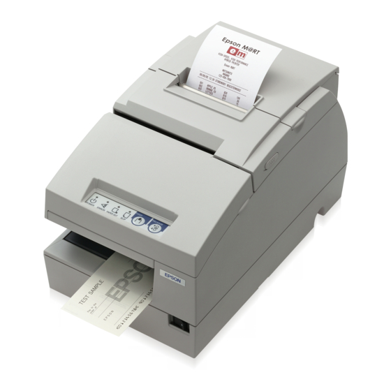
TM-H6000III Technical Reference Guide Chapter 3 Setup 3.1 Part Name and Basic Operation 3.1.1 Part Names Validation entrance (validation model only) roll paper cover unit cover front cover control panel power switch Slip entrance 3.1.2 Connectors WARNING: Do not connect a telephone line to the drawer kick-out connector or the display module connector;... -
Page 62: Important Installation Notes
3.1.2.1 Important Installation Notes ❏ For a serial interface, use a null modem cable. ❏ For a parallel interface, use an IEEE 1284 cable. ❏ For a USB interface, install the driver before connecting the printer. 3.1.3 The Control Panel 3.1.3.1 LED POWER This light is on when the power is turned on. -
Page 63: Control Panel Buttons
TM-H6000III Technical Reference Guide SLIP ❏ This light blinks when the printer is ready to receive slip paper. It stays on during printing on slip paper and blinks again when slip paper should be removed. When the slip paper is removed in the slip removal waiting state, the printer enters the paper roll mode two seconds later. -
Page 64: Validation Paper Handling
Normal Mode All covers are Paper roll cover Unit cover is Front cover is closed is opened opened opened If receipt is FEED Follow ESC/POS Disabled Disabled Follow ESC/POS selected command command RELEASE Follow ESC/POS Enabled command If slip is FEED Follow ESC/POS Follow ESC/POS... -
Page 65: Setup Flow
Complete set up Note: When you use OPOS (OCX driver from EPSON), Advanced Printer Driver, or JavaPOS, you need to install the driver. When you use ESC/POS commands, you don’t have to install drivers. For information on these drivers, see “Control Method” (page 2-1) and “Install a Printer Driver in the Host PC / POS Terminal”... -
Page 66: Printer Setup
3.3.1 Connecting the Power Supply Unit (PS-180) Use the optional EPSON PS-180 power supply or equivalent for your printer. WARNING: Make sure you use the EPSON PS-180 power supply or equivalent. Using an incorrect power supply may cause fire or electrical shock. 3-6 Setup... -
Page 67: Installing Or Replacing The Ribbon Cassette
3.3.2 Installing or Replacing the Ribbon Cassette EPSON recommends the use of genuine EPSON ribbon cassettes. Ribbon cassettes not manufactured by EPSON may cause damage to your printer that is not covered by EPSON’s warranties. To install the ribbon cassette for the first time or to replace a used ribbon, follow the steps below: Note: Be sure to turn on the power before installing a ribbon cassette. - Page 68 1. Unpack the ribbon cassette and turn the knob in the direction shown to take up any slack. Knob 2. Open the front cover of the printer, using the tabs on each side of the cover. 3. Remove the old ribbon, if there is one. 4.
-
Page 69: Installing Or Replacing The Optional Endorsement Ribbon Cassette
EPSON recommends the use of genuine EPSON ribbon cassettes. Ribbon cassettes not manufactured by EPSON may cause damage to your printer that is not covered by EPSON’s warranties. Note: Be sure to turn on the power before installing a ribbon cassette. - Page 70 2. Open the unit cover, as shown below. Inside the printer, push the levers backward to open the unit. Note: Do not open the unit during printing. 3. Insert the ribbon cartridge into the printer. You can see a properly installed ribbon in the illustration below.
-
Page 71: Installing Or Replacing The Paper Roll
TM-H6000III Technical Reference Guide 3.3.4 Installing or Replacing the Paper Roll Note: Do not use paper rolls that have the paper glued or taped to the core because they might cause a paper jam. To prevent paper jams, make sure that nothing obstructs paper coming out of the paper exit, and do not pull the paper out of the printer. -
Page 72: Connecting The Printer To The Host Pc / Pos Terminal
3.3.5 Connecting the Printer to the Host PC / POS Terminal All cables are connected to the connector panel located on the lower rear side of the printer. Drawer kick connector Customer Display Interface connector Power supply connector (DM-D) connector Connector panel Note: The figure above shows the connector panel for the RS-232/RS-485 interface model printer. -
Page 73: Parallel Interface Models
TM-H6000III Technical Reference Guide 3.3.5.2 Parallel Interface Models 1. Press the connector on the end of the interface cable firmly into the interface connector on the connector panel. 2. Press down the clips on either side of the connector to lock it in place. -
Page 74: Connecting A Drawer
3.3.5.4 Connecting a Drawer CAUTION: Be sure to connect a drawer that meets printer specifications. Connecting a drawer of the wrong specifications may result in damage to both the drawer and the printer. Never connect a telephone line to the drawer kick out connector (labeled “DK”). Doing so may result in damage to both the telephone line and the printer. -
Page 75: Customizing
TM-H6000III Technical Reference Guide 3.4 Customizing This printer is able to be customized for the items below: ❏ Roll paper near end detector ❏ DIP switch (communication condition, print density, etc...) ❏ Memory switch (some notices enable/disable, roll paper type, error signal output, paper jam detection for slip, and unit cover open while printing) The current settings can be confirmed by a self-test. -
Page 76: Adjusting The Dip Switches
3.4.3 Adjusting the DIP Switches The printer has two sets of DIP switches. The function of the DIP switches is different for each interface model. 3.4.3.1 Changing the DIP Switch Settings If you need to change settings, follow the steps below to make your changes: CAUTION: Turn off the power while removing the DIP switch cover to prevent an electric short, which can damage the printer. -
Page 77: Serial Interface Model
TM-H6000III Technical Reference Guide 3.4.3.2 Serial interface model DIP Switch 1 Function Data receive error Ignored Prints “?” Receive buffer capacity 45 bytes 4 KB Handshaking XON/XOFF DTR/DSR Data word length 7 bits 8 bits Parity check Enabled Disabled Parity selection Even Transmission speed (See the table below.) -
Page 78: Parallel / Ethernet Interface Model
NOTE: Changes in DIP switch settings (excluding switches 2-7 and 2-8, interface reset signals) are recognized only when the printer power is turned on or when the printer is reset. If the DIP switch setting is changed after the printer power is turned on, the change does not take effect until the printer is turned on again or is reset. -
Page 79: Usb Interface Model
TM-H6000III Technical Reference Guide NOTE: When pin 6 of the interface connector is used for the reset signal, the printer is reset at MARK on the RS-232 level. Changes in DIP switch settings (excluding switch 2-8, interface reset signal) are recognized only when the printer power is turned on or when the printer is reset by using the interface. -
Page 80: When Using Original Paper
NOTE: If the print density is set to level 3 or 4, printing speed is usually reduced. For a tip about print density, see “When Using Original Paper” (page 3-20). 3.4.3.5 When Using Original Paper When you use original paper such as P350 (F380), we recommend setting the DIP switches as shown in the table below. -
Page 81: How To Use Two-Color Printing
3.5 Install a Printer Driver in the Host PC / POS Terminal EPSON provides printer drivers for the TM-H6000III. The drivers are OPOS, Advanced Printer Driver (APD), and JavaPOS. The OPOS and APD are for the Windows environment and the JavaPOS is for the Windows environment and the Linux environment. - Page 82 Outline of the installation and setup procedure is as follows. ❏ Select the device and I/F setting ❏ Device specified setting • Paper type & size setting • Bitmap setting • Color print setting 3-22 Setup Rev. C...
- Page 83 TM-H6000III Technical Reference Guide 1. Installation. Execute the Setup.exe in DISK1 and continue the installation by using the wizards. 2. Setup the device and environment. 1. Set the device setting by using SetupPOS utility. • Select the device and I/F setting.
-
Page 84: Advanced Printer Driver (Apd)
3.5.2 Advanced Printer Driver (APD) 3.5.2.1 Installing and Setting Up When you install and set up the APD, please refer to the “EPSON Advanced Printer Driver Installation Manual.“ The Manual is a PDF file, which is provided with other manuals for the APD. - Page 85 TM-H6000III Technical Reference Guide 1. Install EPSON Advanced Printer Driver Execute the installer “ATM###E.exe,“ and select modules which you need (“###” is a version number). The recommended modules are shown below. Refer to the installation manual for details. EPSON TM-H6000III Slip: This module (printer driver) is needed for printing on the face of a slip.
-
Page 86: Epson Javapos Adk
2. Set up environment variables 3. Check the installation Make sure that the Java2 SDK is correctly installed. 4. Install EPSON JavaPOS ADK Execute the self-extracting EPSON_JPOS_ADK_****.exe file, click [Next>] to start and then follow the wizards. What interface model? -
Page 87: Self Tests
TM-H6000III Technical Reference Guide 3.6 Self Tests The self tests let you know if your printer is operating properly. There are self tests for both roll paper and slip paper. They check the control circuits, printer mechanisms, print quality, control software version, and DIP switch settings. -
Page 88: Running The Self Test With The Validation Paper
3.6.3 Running the Self Test with the Validation paper 1. Make sure the printer is turned off and the printer cover is closed properly. 2. While holding down the FEED button and RELEASE button, turn on the printer using the switch on the front of the printer. - Page 89 TM-H6000III Technical Reference Guide Rev. C Setup 3-29...
- Page 90 3-30 Setup Rev. C...
-
Page 91: Chapter 4 Maintenance & Troubleshooting
TM-H6000III Technical Reference Guide Chapter 4 Maintenance & Troubleshooting This section describes maintenance and general troubleshooting. 4.1 Maintenance 4.1.1 Cleaning the Thermal Print Head CAUTION: After printing, the print head can be very hot. Be careful not to touch it. Also let it cool before you clean it. -
Page 92: Cleaning Sheet
4.1.2.2 Cleaning sheet Use the following or an equivalent commercially available cleaning sheet: PRESAT brand (KIC) “CHECK READER CLEANING CARD.” 4.1.2.3 Cleaning procedure You can perform cleaning either in self mode or command mode. These modes are described below. 4.1.2.4 Self mode 1. -
Page 93: Troubleshooting
TM-H6000III Technical Reference Guide 4.2 Troubleshooting 4.2.1 Removing a Paper Jam CAUTION: Do not touch the paper feed motor because it can be very hot. If the paper is jammed in the paper roll section, turn the printer off. Next, open the paper roll cover. -
Page 94: Autocutter Jam
4.2.2 Autocutter Jam If a foreign object such as a push pin or paper clip drops in the autocutter and causes the auto cutter to lock up, the printer enters an error state and begins the recovery operation automatically. If the problem is not serious, the autocutter returns to its normal position without any intervention by the user. - Page 95 TM-H6000III Technical Reference Guide ❏ Errors that have the possibility of recovery: When a recoverable error occurs, after the cause of the error is removed, the printer can recover from the error by transmitting error recovery command without turning off the...
-
Page 96: Printer Prints "?" Or Incorrect Data With Serial Interface
❏ Errors that are impossible to recover: ERROR LED Blinking Pattern 320 ms ERROR Description Recovery R/W error in memory After R/W checking, the Impossible to recover or gate array printer does not work correctly. Writing to, reading out, or erasing the NV memory for image scanning results does not work correctly. -
Page 97: Hexadecimal Dump
TM-H6000III Technical Reference Guide 4.2.5 Hexadecimal Dump This feature allows experienced users to see exactly what data is coming to the printer. This can be useful in finding software problems. When you turn on the hex dump function, the printer prints all commands and other data in hexadecimal format, along with a guide section to help you find specific commands. - Page 98 4-8 Maintenance & Troubleshooting Rev. C...
-
Page 99: Chapter 5 Application Development Information For Opos
EPSON OPOS ADK provides a tool, “TMFLogo” that enables registration of a bitmap image in the NVRAM of an EPSON TM series printer. The tool can be used from the device specific settings of the SetupPOS utility. The bitmap image in the NVRAM can be printed with a printer by using the DirectIO method. -
Page 100: Supplementary Explanation Of Function
Print Print stored bitmap by DirectIO method. *Command : PTR_DI_PRINT_FLASH_BITMAP The available NVRAM size for the TM-H6000III: ❏ ANK model: max. 384KB ❏ Multilingual model: max. 192KB 5.1.2 Supplementary Explanation of Function 5.1.2.1 LetterQuality It is possible to change the speed and quality of a bitmap by using the XXXLetterQuality property. -
Page 101: Setting Of Printing Position By Escape Sequence
TM-H6000III Technical Reference Guide 5.1.2.2 Setting of printing position by escape sequence POS Printers support escape sequences that can be treated as printing data. The following commands are the escape sequence command for setting of printing position. Name Data Remarks... -
Page 102: Recommended Flow
5.2.1 Recommended Flow Slip printing OPOSPrinter.AsyncMode = False OPOSMICR.BeginInsertion MICR reading procedure ResultCode = SUCESS Error Processing OPOSMICR.EndInsertion ResultCode = SUCESS Error Processing OPOSPrinter.PrintNormal Printing procedure (Endorsement printing) ResultCode = SUCESS Error Processing OPOSPrinter.ChangePrintSide Printing procedure (Right side printing) ResultCode = SUCESS Error Processing OPOSMICR.BeginRemoval Check removal... -
Page 103: Sample Program
TM-H6000III Technical Reference Guide 5.2.2 Sample Program Below is as example of how to use Slip & MICR Combination with OPOS ADK. Dim RC As Long ‘Return Code Dim I = 1 as Integer OPOSPOSPrinter1.AsyncMode = False ‘Paper preparation procedure RC = OPOSMICR1.BeginImsertion(3000) -
Page 104: Cash Drawer
5.3 Cash Drawer Programming examples of how to use API function relating to a Cash Drawer are shown below. 5.3.1 Drawer Open/Close Using the OpenDrawer method opens the cash drawer. The DrawerOpened property can be used to check the current state of the drawer. To pause the program until the drawer is closed, the WaitForDrawerClose method is used. -
Page 105: Chapter 6 Application Development Information For Apd
3. Feed the check to the print start position on the face by ”BiMICRLoadCheck.” 4. Print data on face of the slip. 5. Switch the printer driver to “TM-H6000III Endorsement“ from “TM-H6000III Slip.“ Note: Switch means “Close the “TM-H6000III Slip“ by using “BiCloseMonPrinter“ and Open “TM-H6000III Endorsement“... -
Page 106: Bitmap Printing
2. NV Bit-image EPSON provides a tool, “TMFLogo” that enables registration of a bitmap image in the NVRAM of an EPSON TM series printer. A bitmap image in the NVRAM can be printed with a “control font” method. Function list... -
Page 107: Color Bitmap Printing
TM-H6000III Technical Reference Guide 6.2.2 Color bitmap printing First adjust memory switch 8-4 to print using 2 color. Refer to “3.4.5 How to Use Two-Color Printing (3-21 page)” for details. 6.2.3 Printable bitmap format The printable bitmap formats are formats that meet all the following conditions. -
Page 108: Drawer Control
6.4 Drawer Control 6.4.1 Drawer Open When you control a drawer connected to this printer using APD, you have two methods to open the drawer. The first method is using “Control font”; the second is using “Status API.“ Below is as example of a program (Visual Basic) to open a cash drawer using Control font. 'Execute open cash drawer1. -
Page 109: Appendix A Character Code Tables
TM-H6000III Technical Reference Guide Appendix A Character Code Tables A.1 Page 0 (PC437: USA, Standard Europe) (International Character Set: USA) NOTE: Character code tables show only character configurations, not the actual print pattern. Rev. C Character Code Tables A-1... -
Page 110: Katakana
A.2 Page 1 (Katakana) A-2 Character Code Tables Rev. C... -
Page 111: Pc850: Multilingual
TM-H6000III Technical Reference Guide A.3 Page 2 (PC850: Multilingual) Rev. C Character Code Tables A-3... -
Page 112: Pc860: Portuguese
A.4 Page 3 (PC860: Portuguese) A-4 Character Code Tables Rev. C... -
Page 113: Pc863: Canadian-French
TM-H6000III Technical Reference Guide A.5 Page 4 (PC863: Canadian-French) Rev. C Character Code Tables A-5... -
Page 114: Pc865: Nordic
A.6 Page 5 (PC865: Nordic) A-6 Character Code Tables Rev. C... -
Page 115: Wpc1252
TM-H6000III Technical Reference Guide A.7 Page 16 (WPC1252) Rev. C Character Code Tables A-7... -
Page 116: Pc866: Cyrillic2
A.8 Page 17 (PC866: Cyrillic2) A-8 Character Code Tables Rev. C... -
Page 117: Pc852: Latin2
TM-H6000III Technical Reference Guide A.9 Page 18 (PC852: Latin2) Rev. C Character Code Tables A-9... -
Page 118: Pc858: Euro
A.10 Page 19 (PC858: Euro) A-10 Character Code Tables Rev. C... -
Page 119: Space Page
TM-H6000III Technical Reference Guide A.11 Page 254 (Space Page) NOTE: Page 254 is supported only when printing on the face of a slip. When font A is selected, character codes 80H to FFH are all spaces. When font B is selected, the font above is defined as the default. -
Page 120: A.12 Page 255 (Space Page)
A.12 Page 255 (Space Page) NOTE: In printing on the face of a slip with page 255, the font is selected as above, when font A is selected, character codes 80H to FFH are all spaces, when font B is selected, the following font is defined as the default. -
Page 121: International Character Sets
TM-H6000III Technical Reference Guide A.13 International Character Sets ASCII code (Hex) Country 23 24 40 5B 5C 5D 5E 60 7B 7C 7D 7E U.S.A France à ° ç § é ù è ¨ Germany § Ä Ö Ü ä... - Page 122 A-14 Character Code Tables Rev. C...
-
Page 123: Appendix B Power Supply Specifications
TM-H6000III Technical Reference Guide Appendix B Power Supply Specifications This appendix describes the optional power supply unit (PS-180). B.1 PS-180 (Energy Saving Power Supply Unit) B.1.1 Electrical Characteristics ❏ Input conditions Input voltage (rating): 90 to 264VAC (100 VAC -10% to 230 VAC +15%) -
Page 124: Case Specifications
B.1.2 Case Specifications ❏ Size: × × 68 mm (D) 136 mm (L) 32 mm (H) (excluding projections) Refer to the figure below. ❏ Mass: Approx. 0.4 kg (excluding the AC cable) ❏ Material: Flame-resistance grade: V0 ❏ Color: Black (mat) Case specifications Material No specific brominated flame retardants such as PBBE, PBB are used in this product. -
Page 125: Appendix Cfaq
TM-H6000III Technical Reference Guide Appendix C C.1 Serial Interface C.1.1 The printer does not operate correctly or the printer does not print. What should I do? ❏ Confirm that the cable is connected correctly. • Is the cable wiring between the printer and the host PC correct? See the wiring cable diagrams shown in “What is the cable wiring for connecting a printer and a host PC with... -
Page 126: What Is The Cable Wiring For Connecting A Printer And A Host Pc With A Serial Interface
• If the DM is connected to the DM connector of the UB-S09, confirm that the settings of the jumper switch on the UB-S09 are correctly set. JP 1 1-2 shorted 2-3 shorted Customer display connected Customer display not connected Customer display connection settings Note:... -
Page 127: How Many Printers Can Be Connected
TM-H6000III Technical Reference Guide ❏ 9 pin (PC) - 9 pin (Interface) SHELL FG 2 RXD 3 TXD 4 DTR 5 SG 6 DSR 7 RTS 8 CTS (Reserved) 9 INIT(*1) Reset signal (*1) When the reset signal of the host PC is used. -
Page 128: Parallel Interface
C.2 Parallel Interface C.2.1 The printer does not operate correctly or the printer does not print. What should I do? ❏ Confirm that the cable is connected correctly. • Is the cable wiring between the printer and the host PC correct? For details, see the table in “What is the cable wiring for connecting the printer and the host PC with a parallel interface?”... -
Page 129: How Many Printers Can Be Connected
TM-H6000III Technical Reference Guide ❏ Be sure to use a cable conforming to IEEE1284 standards. The pin assignments of the interface are shown below. Source Compatibility Mode Nibble Mode Byte Mode Host nStrobe HostClk HostClk Host/Printer Data0(LSB) Data0(LSB) Data0(LSB) Host/Printer... -
Page 130: Is There Limitation For The Length Of A Cable
C.2.6 When I turned on the printer with a parallel interface and then turned on the PC, the message “New hardware has been found.” appeared and the device “EPSON TM-Px.xx” was detected. What is “EPSON TM-Px.xx”? ❏ It is the device ID of the parallel interface board used with the TM printer. Regardless of the connected printer model, it is the common name. -
Page 131: The Dm Does Not Operate Correctly. What Should I Do
❏ Confirm that the interface is correctly recognized by the host PC. • Confirm that [EPSON USB Controller for TM Printer Series] appears in the device manager of the host PC. If the UB-U01/U01II/U02II is used, [General USB Hub] also appears. -
Page 132: What Should Be Considered For A Usb Connection
❏ Confirm that the TM printer and the DM are turned on. Be sure to check that the power of all necessary devices is turned on. ❏ Confirm that the power of the DM has been turned on before turning on the power of the TM printer. -
Page 133: What Should Be Considered For A Dm Connection
TM-H6000III Technical Reference Guide 4. Turn off the printer and turn it on again. 5. Confirm that EPSON USB Controller for TM/BA/EU Printers is shown in Universal Serial Bus controllers. 6. Open the port tab of the printer property; change the port USB001 to TMUSB000-Printer. -
Page 134: Usb Connection
• HighSpeed (when the host controller is USB 2.0, a USB 2.0 hub is used, or a TM printer is a HighSpeed model) Windows 2000 SP4 or later Windows XP SP1 or later (Windows 98SE is not guaranteed.) ❏ Operating USB host controller INTEL: Built-in chip USB host controller NEC:... - Page 136 EPSON SEIKO EPSON CORPORATION...