Table of Contents
Advertisement
Advertisement
Table of Contents

Related Manuals for Minolta 5600HS (D)


Summary of Contents for Minolta 5600HS (D)
- Page 1 PROGRAM FLASH MAXXUM FLASH 5600HS ( D ) E INSTRUCTION MANUAL...
- Page 2 • the product emits a strange smell, heat, or smoke. Do not disassemble. Electric shock may occur if a high voltage cir- cuit inside the product is touched. Take your flash to a Minolta Service Facility when repairs are required.
-
Page 3: Table Of Contents
56, a high-intensity light source, and a wide range of functions in a compact body, and is designed for use with Minolta auto-focus single lens reflex cameras. Please read this manual thoroughly before using this flash. We... -
Page 4: Cameras And Flash Units
MAXXUM/PROGRAM FLASH 3600HS (D) This flash unit is designed and manufactured solely for use with the Minolta Maxxum/Dynax series cameras. It cannot be attached to other Minolta cameras. Performance when used with cameras from other manufacturers cannot be guaranteed. Minolta takes no responsibility for accidents or malfunctions due to use with such cameras. -
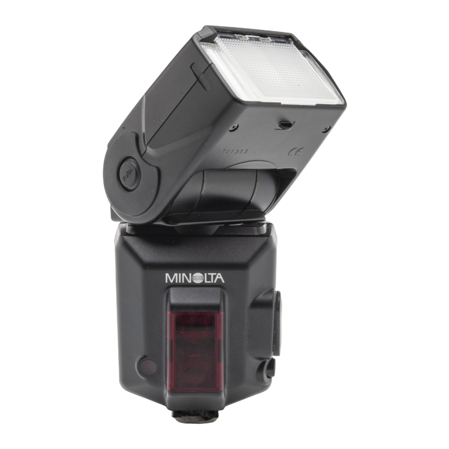
Page 5: Names Of Parts
NAMES OF PARTS Flash Unit Diagram Built-in wide angle Terminal cap adapter (25) Inside terminal Accessory terminal (55) External-power terminal (72) Flashtube AF illuminator (33) Wireless/Remote control-signal receiver (42) Bounce indica- tor (28) Data panel (10) Control panel (9) Figures in brackets after each item indicate the relevant page. Control Panel Mode button Mounting-foot-release... -
Page 6: Basic Operation
NAMES OF PARTS Data Panel Wireless/Remote controller Flash-range-warning indicators (18) indicator (48) Flash-range (18)/Multiple-flash- High-speed-sync frequency display (60) indicator (38) Wireless/Remote flash indicator (46-54) Flash-ok indicator (17) TTL indicator (36) Manual-flash-control indicator (36) Multiple-flash indicator (60) Custom indicator (65) Ratio-flash indicator (50, 53, 56) Power-level indicator (58) Zoom/Multiple-flash-... -
Page 7: Installing Batteries
INSTALLING BATTERIES The 5600HS (D) may be powered by : • Four AA-size alkaline batteries • Four AA-size lithium batteries • Four AA-size rechargeable nickel-metal hydride (Ni-MH) batteries Always ensure that rechargeable nickel-metal hydride batteries are charged in the specified charger unit. 1. -
Page 8: Attaching And Removal
ATTACHING AND REMOVAL Attaching To The Camera Push the mounting foot firmly onto the camera until it stops. • The flash is locked in place automati- cally. • If the built-in flash in the camera is protruding, lower it before fitting the flash unit. -
Page 9: P Mode Flash: The Basics
P MODE FLASH: THE BASICS 1. Select the P mode on the cam- era. 2. Press the flash ON/OFF button to display 3. Press the shutter-release but- ton partway down. • matic flash. Only fill flash. • With the Maxxum/Dynax 7, automatic flash is used with and fill flash when the P mode is selected. -
Page 10: Exposure Modes
P MODE FLASH: THE BASICS Flash Range Press the shutter-release button part- way down to display the flash range for the proper exposure on the data panel. Check that the subject is within this range and then take the photo. A distance range of 1.5~28m may be displayed on the data panel (0.7~28m for downward bounce, see p. -
Page 11: M Mode Flash
EXPOSURE MODES M Mode Flash 1. Select the M mode on the camera. 2. Press the flash on/off button to display • Fill flash is selected. 3. Set the aperture and shutter speed, and focus the sub- ject. • Reduce the aperture (ie increase the f-stop) to reduce the flash range, or open the aperture (ie reduce the f-stop) to increase the flash range. -
Page 12: Applications
APPLICATIONS The section explains the various methods available to make full use of the flash unit. ZOOM FLASH COVERAGE Auto Zoom 24mm focal length 85mm focal length This flash unit employs auto zoom to cover a range of focal lengths from 24mm to 85mm. - Page 13 ZOOM FLASH COVERAGE Manual Zoom Zoom may be set manually irrespective of the focal length currently in use. Press the ZOOM button to dis- play the desired zoom coverage. • Zoom coverage is changed in the following order. Auto zoom, 24mm, 28mm, 35mm, 50mm, 70mm, 85mm •...
-
Page 14: Test-Flash/Modeling Flash
TEST-FLASH/MODELING FLASH One or more test flashes may be tried before photographing. This is particularly convenient for checking shadows when the flash is sep- arated from the camera such as in wireless flash. * Modeling flash is used to check shadows on the subject before taking pho- tos. -
Page 15: Bounce Flash
BOUNCE FLASH Strong shadows appear when flash is used with a wall directly behind the subject. In such cases the flash is directed at the ceiling etc. so that the subject is illuminated with reflected light, and the intensity of the shadows are reduced to produce a softer light in the photograph. -
Page 16: Close-Up Photography (Downward Bounce)
BOUNCE FLASH Adjusting Bounce Angle An unsightly photo results when both direct light and bounced light from the flash are used simultaneously. Determine the bounce angle in reference to the distance to the reflective surface, the distance from the camera to the subject, and the focal length of the lens etc. -
Page 17: Data Panel Illuminator
DATA PANEL ILLUMINATOR Illuminates the data panel at low-light levels. Press the data panel illuminator. • The data panel is illuminated for approximately eight seconds. This period is extended if the flash is used during this time. • To extinguish the data panel illumina- tor, press the button again while the data panel is illuminated. -
Page 18: Mode And Select Buttons
MODE AND SELECT BUTTONS The mode, select, +, and - buttons are used to select the functions described on the next page. The functions are selected with the following basic procedure. See the relevant pages for details. 1. Select the major item with the mode button. 2. -
Page 19: Manual Flash (M)
MANUAL FLASH (M) Normal TTL flash metering automati- cally adjusts the flash intensity to pro- vide the proper exposure for the sub- ject. Manual flash provides a fixed flash intensity irrespective of the brightness of the subject and the camera setting. •... -
Page 20: High-Speed Sync (Hss)
HIGH-SPEED SYNC (HSS) High-speed sync High-speed sync eliminates the restrictions of flash sync speed, and allows you to use flash over the entire shutter speed range of the camera. The selectable aperture range is increased, allowing portrait shots with flash in which the aperture is opened to leave back- grounds out of focus and thus accentuate the human subject. -
Page 21: Wireless/Remote Flash Mode
(D), 5400HS, or 5400xi, and one 3600HS (D) or 3500xi. [1] Using the built-in flash (p. 46) The following two modes are available. • Use only an off-camera flash unit (photo , p. 40). • Use the built-in flash, and an off-cam-... -
Page 22: Wireless Flash Range
• Install the off-camera flash within the gray area in the following dia- gram. See the flash unit manual for details of the distance between the flash and the subject (Table 2) for all except the 5600HS (D). -
Page 23: Notes On Wireless Flash
(p. 65). • Make sure that RATIO is not displayed on the data panel of the off- camera flash except using with the Wireless Remote Flash Controller. If ratio is selected with the off-camera flash, proper exposure will not be obtained. -
Page 24: Using The Built-In Flash
WIRELESS/REMOTE FLASH MODE [1]-1 Using The Built-In Flash 1. Attach the 5600HS (D) to the camera and switch the flash and camera power supplies on. 2. Set the camera to wireless flash. • The method used for the setting varies with the camera. See the cam- era manual for details. -
Page 25: Using Two Flash Units
5. Press the select button repeatedly until blinking stops. • The 5400HS, 5400xi, or 3500xi may be used as the off-camera flash. See the flash manual if using the 5400HS. Display [W.L-F.1] if using the 5400xi. Press and hold the on/off button until wireless indicator glows if using the 3500xi. - Page 26 • See page 43 for details. • When using the 5600HS (D) as the controller and a flash other than the D flash (see page 6) as the off-camera flash, ensure that the shutter speed does not exceed the flash sync speed for the camera.
-
Page 27: Using Wireless Remote Flash Controller
Using 5600HS (D), 5400HS, 5400xi only (The following applies for 5600HS (D). See flash or Wireless Remote Flash Controller manual for other flashes.) 1. Set up the 5600HS (D) with the off-camera flash as described in 1~4 on page 52~53. Continued on next page... -
Page 28: Connecting Camera And Flash By Cable
4. Press the select button. Using with 3600HS (D) or 3500xi Set up the 5600HS (D) with the wireless ratio off-camera flash in the same way as described in 1~4 on page 53~54, and select Set up the 3600HS (D) or 3500xi with the wireless off-camera flash. - Page 29 CONNECTING CAMERA AND FLASH BY CABLE Equalizing The Power Level Of All Flash Units All the flash units in A and B group can be used. 1. Connect the flash units with off-camera cables. 2. Switch all flash units on. 3.
-
Page 30: Setting Power Level (Level)
SETTING POWER LEVEL (LEVEL) The power level for the flash can be adjusted. 1. Press the select button to dis- play [LEVEL] on the data panel. • The current level is displayed. • This step may be ignored when man- ual flash 2. -
Page 31: Multiple Flash (Multi)
MULTIPLE FLASH (MULTI) The flash is triggered a number of times while the shutter is open. Multiple flash allows motion of the subject to be captured in a photo- graph for later analysis. • The camera must be set to the M (manual) mode for multiple flash pho- tography. - Page 32 MULTIPLE FLASH (MULTI) 7. Press the select button to blink [LEVEL] on the data panel. • The current power level is displayed. 8. Press the + or – button to select the power level to be set. • The power level may be selected from the following.
-
Page 33: Reset To The Default Settings
RESET TO DEFAULT SETTINGS Most of the flash functions return to the default settings, as follows, if both the + button and – button are pressed and held for three seconds. Item Flash on/off On (Auto on or on) Flash coverage (zoom) Auto zoom (85mm) Flash mode (TTL/M/MULTI) High speed sync (HSS) -
Page 34: Wireless Channel Setting
CUSTOM FUNCTION Select with the + button or – button 1. Wireless channel setting Channel 1 Channel 2 2. Flash range units (m/ft) 3. Time to auto power off 4 minutes 15 minutes 4. Time to auto power off when using wireless 60 minutes none 5. -
Page 35: Appendix
APPENDIX USE IN COMBINATION WITH OTHER PRODUCTS Read this manual in combination with the relevant manual when any of the following products are used in combination with the 5600HS (D). Using xi Series Single Lens Reflex Cameras (Maxxum/Dynax 9xi, 7xi, 5xi, 3xi, SPxi, 2xi) •... - Page 36 USE IN COMBINATION WITH OTHER PRODUCTS Using Early AF Series Single Lens Reflex Cameras (Maxxum/Minolta 9000, 7000, 5000) • The optional flash shoe adapter FS-1200 is necessary. See the FS- 1200 manual for details. Using APS Single Lens Reflex Cameras (Vectis S-1, S-100) •...
-
Page 37: Accessories
ACCESSORIES Off-Camera Accessories The following off-camera accessories are available. • Off-camera cable • Off-camera shoe • Extension cable • Cable CD • Triple connector TC-1000 The off-camera cable allows the flash to be used from any position. Use of the extension cable allows of the distance from the camera to be further extended. -
Page 38: Cautions While Handling
CAUTIONS WHILE HANDLING During Photography • This flash unit generates strong light, and should therefore not be used in front of the eyes. Batteries • Do not store the flash unit with the alkaline batteries inside it. Leakage from the batteries may damage the battery chamber. •... -
Page 39: Performance
PERFORMANCE Guide number Normal flash (ISO 100) Flash Coverage Setting (mm) Power level 6.4 10 1/16 4.5 7.5 1/32 3.2 5.3 5.7 6.7 7.8 8.8 9.7 Wireless flash (ISO 100) Flash Coverage Setting (mm) Power level HSS flat flash (flash with HSS, ISO 100) Flash Coverage Setting (mm) Shutter speed 1/250... - Page 40 MEMO...