
Related Manuals for Bad Boy Onslaught 550 EFI 4X4


Summary of Contents for Bad Boy Onslaught 550 EFI 4X4
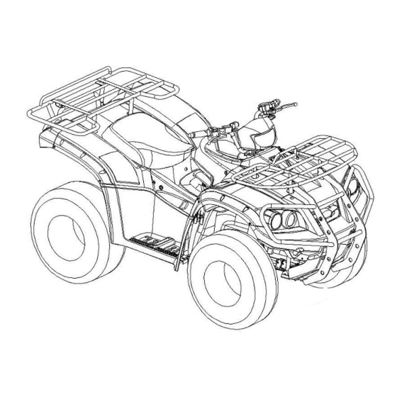
- Page 1 READ THIS MANUAL CAREFULLY! It contains important safety information. 550 EFI 4X4 / 550 EFI 4X4 EPS OWNER’S MANUAL This vehicle should not be operated by those under 16 years of age. 647524...
- Page 2 Dear customer: Our ATV is manufactured under a strict quality control system. Separate documents supplied to the dealer provide information on Product Warranty and Emissions Warranty. Failure to follow instructions for emission parts replacement may violate U.S. Federal Law (40 CFR part 1068.105 (b)) and be subject to fines and other penalties as described in the Clean Air Act.
- Page 3 therefore is subject to change without notice. The manufacturer DISCLAIMS LIABILITY FOR ERRORS IN THIS MANUAL, and SPECIFICALLY DISCLAIMS LIABILITY FOR INCIDENTAL AND CONSEQUENTIAL DAMAGES resulting from the use of the information and material in this manual. NAME: ADDRESS: TELEPHONE: PURCHASE DATE: mm/dd/yyyy ATV MODEL:...
- Page 4 INTRODUCTION Read this manual carefully before operating this vehicle. This manual should stay with vehicle if it is sold. This manual will provide you with a good basic understanding of the features and operation of this ATV. This manual includes important safety information. It provides information about special techniques and skills necessary to ride the ATV.
-
Page 5: Table Of Contents
CONTENTS SPECIFICATIONS………………………………………………………………………… IMPORTANT IDENTIFICATION NUMBERS…………………………………………… LOCATION OF THE WARNING AND SPECIFICATION LABEL…………………….. SAFETY INFORMATION…………………………………………………………………. PRE-OPERATION CHECKS…………………………………………………………….. DESCRIPTION…………………………………………………………………………….. INSTRUMENT AND CONTROL FUCTION…………………………………………….. IGNITION SWITCH FUNCTION/POSITION…………………………………………. SIGNS AND FUNCTION………………………………………………………………. FOUR WHEEL BRAKE LEVER (WITH PARKING BRAKE) ………………………… REAR BRAKE PEDAL ………………………………………………………… SHIFT LEVER…………………………………………………………………………… 2WD/4WD/LOCK SWITCH………………………………….…………………………... -
Page 6: Specifications
SPECIFICATIONS 550 EFI 4X4 Overall Length 84.8 in. (2155 mm) Overall Width 48.6 in. (1235 mm) Overall Height 49.2 in. (1250 mm) Wheel Base 50.4 in. (1280 mm) Front 36.6 in. (930 mm) Wheel tread Rear 37.0 in. (940 mm) Front 472 lbs. - Page 7 Rear Disk (Ø 180 mm) Max. Speed 78 [km/hr] Performance <25 ゚ Climb Ability Primary Reduction Belt Secondary Reduction Gear / Shaft Reduction Clutch Centrifugal, wet type Transmission C.V.T., auto speed change Speedometer 0 ~ 300 [km/hr] Horn 93 ~ 112 [dB/A] Fuel capacity 18 +/- 0.3 l Lubrication System...
-
Page 8: Important Identification Numbers
IMPORTANT IDENTIFICATION NUMBERS 1. Frame Number: Record chassis and engine number for future reference. Number is located front right hand side of chassis as shown in (1). 2. Engine number is located front of the engine as shown in (2). 3. -
Page 9: Location Of The Warning And Specification Label
LOCATION OF THE WARNING AND SPECIFICATION LABELS... - Page 10 Read and understand all of the labels on your ATV. These labels contain important information for safe and proper operation. Never remove any labels from your ATV. If a label becomes difficult to read or comes off, request a replacement label from your dealer.
-
Page 14: Safety Information
SAFETY INFORMATION AN ATV IS NOT A TOY AND CAN BE HAZARDOUS TO OPERATE An ATV handles differently from other vehicles, including motorcycles and cars. A collision or rollover can occur quickly, even during routine maneuvers such as turning and riding on hills or over obstacles, if you fail to take proper precautions. - Page 15 Always follow proper procedures for climbing hills as described in this manual. Check the terrain carefully before you start up any hill. Never climb hills with excessively slippery or loose surfaces. Shift your weight forward. Never open the throttle suddenly. Never go over the top of a hill at high speed.
- Page 16 WARNING! All engine exhaust contains carbon monoxide, a deadly gas. Carbon Monoxide is a colorless, odorless, tasteless gas, which may be present even if you do not see or smell any engine exhaust. Avoid Carbon Monoxide Poisoning. Do not run engine indoors. Even if you try to ventilate engine exhaust with fans or open windows and doors, carbon monoxide can rapidly reach dangerous levels.
-
Page 17: Pre-Operation Checks
PRE-OPERATION CHECKS Inspect your vehicle each time you use it to make sure the vehicle is in safe operating condition. Always follow the inspection and maintenance procedures and schedules described in Owner’s Manual. WARNING! Failures to inspect or maintain the vehicle properly increase the possibility of accident or equipment damage. - Page 18 Make sure that operation is smooth. Lubricate pedal pivoting Brake pedal point if necessary. Make sure that operation is smooth. Lubricate pedal pivoting Brake levers point if necessary. Check for cracks or damage and replace if necessary. Axle boots ...
-
Page 19: Description
DESCRIPTION 1. Stop Switch 8. Auxiliary DC jack 2. High/Low beam Switch 9. 2WD/4WD/LOCK Switch 3. Four Wheel Brake Lever 10. Throttle 4. Starter Switch 11. Fuel Tank Cap 5. Override 12. L/H/N/R Lever 6. Ignition Switch 13. Parking Brake 7. -
Page 20: Instrument And Control Fuction
INTRUMENT AND CONTROL FUNCTION 1. IGNITION SWITCH FUNCTION / POSITION Position Function Key Out Position Lamp All electrical systems operational While parking 2. SIGNS AND FUNCTIONS Position Name Function Starter Switch Start engine Dimmer Switch Hi-Beam/Lo-Beam Switch Stop Switch Stop engine Run Engine Engage the engine to run Turn Signal Switch... -
Page 21: Rear Brake Pedal
12 mm 4. REAR BRAKE PEDAL The rear brake (pedal) is located on the right side of the ATV. To apply the rear brake, push down on the brake pedal. WARNING! Before each trip check whether the accustomed resistance is present when pressure is applied to the brake lever. -
Page 22: Shift Lever
5. SHIFT LEVER L: High torque use (advance gear) H: Normal use (driving gear) N: Neutral R: Reverse use Shift lever instructions: Engine starts only in Neutral (N) position. Lift up and hold the pull rod of shift lever to disengage and move the shift lever from N to H, L or R. -
Page 23: 2Wd/4Wd/Lock Switch
6. 2WD/4WD/LOCK SWITCH The 2WD/4WD/LOCK SELECT BUTTON is used to change the engine drive power to two wheels or all four wheels. Select 2WD, 4WD or LOCK based on different terrain conditions. 2WD: Engage the engine power on rear wheels only. This is mainly used for normal riding. - Page 24 4WD/LOCK WARNING! Always ride at a slow speed when the ATV is in differential gear lock and allow extra time and distance for maneuvers. All wheels turn at the same speed when the differential gear is locked, so it takes more effort to turn the ATV.
-
Page 25: Tires
Stop the ATV, make sure the 4WD button is pushed in, then turn the differential gear lock lever to the LOCK position. When the differential gear is locked, the differential gear lock indicator “LOCK” will come on along with the indicator “ “... - Page 26 Set the tire pressure to the following specifications: Model 550 EFI 4x4 550 EFI 4x4 EPS 7 psi (0.492kgf/㎝ 6 psi (0.422kgf/㎝ Front Recommend 7 psi (0.492kgf/㎝ 6 psi (0.422kgf/㎝ Rear The low-pressure tire gauge is included as standard equipment. Make two measurements of the tire pressure and use the second reading.
-
Page 27: Coolant
Aftermarket tires and rims The tires and rims that came with your ATV were designed to match the performance capabilities and to provide the best combination of handling, braking and comfort. Other tires, rims, sizes and combinations may not be appropriate. 8. - Page 28 1. Place the ATV on a level surface. Turn the key to the OFF position and remove it from the vehicle. 2. Remove front cover. 3. Place a container under the engine and then remove the coolant drain bolt and its gasket. 4.
-
Page 29: Steering Lock
9. STEERING LOCK The steering lock in principle should be used for theft protection. The handlebar is to be turned to the left and the key in the steering lock pressed and turned simultaneously as shown. Remove key. 10. SPEEDOMETER PANEL DESCRIPTIONS 1. - Page 30 indicator will run a self-diagnostic. If the system does not run the self-diagnostic program there is a malfunction in the system. Please contact your local dealer for inspection. 4. Turn signal light (Green): on use of turn signal, lights will flash with an audible warning. Hazard warning: both left and right turn signal lights will flash with and audible warning.
- Page 31 1. Calculates total operation time from the beginning of vehicle use. 2. Count automatically begins with vehicle movement. 3. TT data is stored in memory even when power is off. Fuel Meter (Only for models with the function) 1. 7 bar graphic indicator of fuel status. 2.
-
Page 32: Spark Plug
11. SPARK PLUG Checking the spark plug. The spark plug is an important engine component, which is easy to check. Since heat and deposits will cause any spark plug to slowly erode, the spark plug should be removed and checked in accordance with the periodic maintenance and lubrication chart. -
Page 33: Air Cleaner
12. AIR CLEANER Clamp Strip Screw Remove the seat. Release the four latches that secure the air cleaner cover, remove the cover. Loosen the clamp strip screw and remove the air cleaner element. Clean the element with non-flammable solvent. WARNING! Always use parts cleaning solvent to clean the sponge material. - Page 34 NOTE: The engine oil should be between the minimum and the maximum level mark. 5. If the engine oil is not between the minimum and the maximum level mark, add sufficient oil of the recommended type to raise it to the correct level. NOTE: Be sure the engine oil is at the correct level, otherwise engine damage may result.
-
Page 35: Differential Gear Oil
With oil filter replacement: 4 quarts (3.86 L) ※ Be sure to wipe off spilled oil on any parts after the engine and exhaust system have cooled down. CAUTION! In order to prevent clutch slippage (since the engine oil also lubricates the clutch), do not mix any chemical additives. -
Page 36: Final Gear Oil
3. Remove the differential gear oil filler bolt, the differential gear oil drain bolt and their gaskets to drain the oil from the differential gear case. Drain bolt NOTE: Dispose of lubricant in accordance with local regulations. 4. Install the drain bolt and its new gasket and then tighten the bolt to the specified torque. Tighten torque: 32.36 Nm or 24 ft. -
Page 37: Seat
To change the final gear oil Place the ATV on a level surface and raise up with a lift or jack. Place an oil pan under the final gear case to collect the used oil. Remove the final gear oil filler bolt; the final gear oil drain bolt and their gaskets to drain the oil form the final gear case. -
Page 38: Battery And Fuse
Drain plug When storing any documents in the storage compartments, be sure to wrap them in a plastic bag so that they will not get wet. When washing the ATV, be careful not to let any water enter the storage compartments. - Page 39 To charge the battery If the battery is discharged and will not allow the vehicle to start. Use a constant voltage battery charger to charge the battery. Keep in mind that the battery tends to discharge more quickly if the ATV is equipped with optional electrical accessories.
- Page 40 For Non EPS model, the MAXI fuse is located beside the starter relay. Replacing a fuse The main fuse box and the EPS fuse box are located under the seat. If a fuse is blown, replace it as follows. 1. Turn the key to “OFF” and turn off all electrical circuits. CAUTION! To prevent accident short-circuiting;...
-
Page 41: Replacing A Headlight Bulb
19. REPLACING A HEADLIGHT BULB If a headlight bulb burns out, replace it as follows. Disconnect the wiring connector. Turn the headlight bulb counterclockwise then remove it. Adjusting screw Bulb Connector Insert a new headlight bulb, and turn clockwise to lock in place. Connect the wiring connector. -
Page 42: Auxiliary Dc Jack
Remove the tail / brake light bulb holder (together with bulb) by turning it counterclockwise. Holder Remove the burnt out bulb by pushing it in and turning it counterclockwise. Insert a new bulb into the bulb holder, push it in and then turn it clockwise until it stops. Install the bulb holder (together with the bulb) by turning it clockwise. -
Page 43: Precaution Of Atv Riding
PRECAUTION OF ATV RIDING This ATV is for recreation and utility use. This section, riding your ATV, provides general ATV riding instructions for recreational riding. The skills and techniques described in this section however are appropriate for all types of riding. Riding your ATV requires special skills acquired through practice over a period of time. - Page 44 This ATV is designed to carry the operator and cargo only, passengers are prohibited. The long seat is to allow the operator to shift position as needed during operation. It is not for carrying passengers. WARNING! Never carry a passenger. Carrying a passenger on this ATV greatly reduces your ability to balance and control this ATV.
- Page 45 WARNING! Never consume alcohol or drugs before or while driving this ATV. You increase your chance of an accident. Pre-operation checks Always inspect your ATV each time you use it to make sure the ATV is in safe operating condition. Perform the pre-operation checks listed on this manual.
- Page 46 Never modify this ATV through improper installation or use of accessories or other modification. All parts and accessories added to this ATV should be genuine Bad Boy or equivalent components designed for use on this ATV and should be installed and used according to instructions. If you have questions, please consult an authorized ATV dealer.
- Page 47 Cleaning the spark arrester Be sure the exhaust pipe and muffler are cool before cleaning the spark arrester. 1. Remove the bolts. 2. Remove the tailpipe by pulling it out of the muffler. 3. Tap the tailpipe lightly, and then use a wire brush to remove any carbon deposits from the spark arrester portion of the tailpipe and inside of the tailpipe housing.
- Page 48 WARNING! Failure to use extra care when operating on excessively rough, slippery or loose terrain could cause loss of traction or ATV control which could result in an accident, including an overturn. When riding in an area where you might not easily be seen such as desert terrain, mount a caution flag on the ATV.
- Page 49 To achieve maximum traction while riding off-road, the two rear wheels turn together at the same speed. Therefore, unless the wheel on the inside of the turn is allowed to slip or lose some traction, the ATV will resist turning. A special turning technique must be used to allow the ATV to make turns quickly and easily.
- Page 50 Shift your weight forward. Never open the throttle suddenly. The ATV could flip over backwards. Never go over the top of any hill at high speed. An obstacle, a sharp drop or another vehicle or person could be on the other side of the hill. ...
- Page 51 WARNING! Stalling, rolling backwards or improperly dismounting while climbing a hill could result in ATV overturning. If you cannot control the ATV, dismount immediately on the uphill side. RIDING DOWN HILL WARNING! Going down a hill improperly could cause overturns or loss of control. Always follow proper procedures for going down hills as described in this Owner’s Manual.
- Page 52 CROSSING A SLOPE WARNING! Improperly crossing hills or turning on hills could cause loss of control or cause the ATV to overturn. Always follow proper procedures as described in the Owner’s Manual. Avoid hills with excessively slippery or loose surfaces. ...
- Page 53 WARNING! Wet brakes may have reduced stopping ability, which could cause loss of control. After riding your ATV in water, be sure to drain the trapped water by removing the check hose at the bottom of the air filter case, remove the v-belt case drain bolt and front storage compartment drain plug to drain any water that may have accumulated.
- Page 54 WHAT TO DO If your ATV doesn’t turn when you want it to: Bring ATV to a stop and practice the turning maneuvers again. Be sure you are putting your weight on the footboard to the outside of the turn. Position your weight over the front wheels for better control ...
-
Page 55: Periodic Maintenance
PERIODIC MAINTENANCE Periodic inspection, adjustment and lubrication will keep your vehicle in the safest and most efficient condition possible. Safety is an obligation of the vehicle owner/operator. WARNING! Failure to properly maintain the vehicle or performing maintenance activities incorrectly may increase your risk of injury or death during service or while using the vehicle. If you are not familiar with vehicle service, have a dealer perform the service. - Page 56 Engine oil filter Replace Engine oil Clean strainer Change Differential Check ATV for oil leakage and correct if gear oil Replace every 4 years necessary Change Check ATV for oil leakage and correct if Final gear oil Replace every 4 years necessary...
- Page 57 Check operation and correct if necessary Shock absorber Check for oil leakage and replace if assemblies necessary Rear knuckle Lubricate with grease pivots 23 Steering shaft Lubricate with grease Check operation and repair or replace if Steering damaged system...
-
Page 58: Cleaning And Storage
CLEANING AND STORAGE Cleaning Frequent, thorough cleaning of your ATV will not only enhance its appearance but will improve its general performance and extend the useful life of many components. Before cleaning the ATV: a. Block off the end of the exhaust pipe to prevent water entry. A plastic bag and strong rubber band may be used. - Page 59 Follow all the instructions in the “Cleaning” section of this chapter. Turn the fuel cock lever to “OFF”. Drain the carburetor float chamber by loosening the drain bolt; this will prevent fuel deposits from building up. Pour the drained fuel into the fuel tank. Fill up the fuel tank and add fuel stabilizer (if available) to prevent the fuel from deteriorating.
-
Page 60: Troubleshooting
TROUBLE SHOOTING Contact your dealer for service if you're unable to identify solutions using the following charts. Engine doesn’t turn over Possible cause Solution Tripped circuit breaker Reset the breaker Low battery voltage Recharge battery to 12.5 VDC Loose battery connections Check all connections and ignition Loose solenoid connections Check all connections and ignition... - Page 61 Loose ignition connections Check all connections and tighten Water present in fuel Replace with new fuel Low battery voltage Recharge battery to 12.5 VDC Kinked or plugged fuel vent line Inspect and replace Incorrect fuel Replace with recommended fuel Clogged air filter Inspect and clean or replace Reverse speed limiter malfunction See your dealer...
-
Page 62: Maintenance Record
MAINTENANCE RECORD P.D.I. 1st Service Date: Date: Odometer reading: Odometer reading: Dealer stamp: Dealer stamp: 2nd Service 3rd Service Date: Date: Odometer reading: Odometer reading: Dealer stamp: Dealer stamp: 4th Service 5th Service Date: Date: Odometer reading: Odometer reading: Dealer stamp: Dealer stamp: 6th Service 7th Service... - Page 63 Service 9th Service Date: Date: Odometer reading: Odometer reading: Dealer stamp: Dealer stamp: 10th Service 11th Service Date: Date: Odometer reading: Odometer reading: Dealer stamp: Dealer stamp: 12th Service 13th Service Date: Date: Odometer reading: Odometer reading: Dealer stamp: Dealer stamp: 14th Service 15th Service Date:...
-
Page 64: Consumer Information
CONSUMER INFORMATION IDENTIFICATION NUMBER Record the key identification number, vehicle identification number and model label information in the spaces provided below for assistance when ordering spare parts from your dealer or for reference in case the ATV is stolen. KEY IDENTIFICATION NUMBER: ___________________________ VEHICLE IDENTIFICATION (FRAME) NUMBER: ___________________________... -
Page 65: 2016 My Emissions Control System Warranty
2016 MY EMISSIONS CONTROL SYSTEM WARRANTY: Bad Boy Onslaught 550 Emission System Warranty Statement: DISTRIBUTORS' LIMITED WARRANTIES EMISSION CONTROL SYSTEMS Your Textron Specialized Vehicles' ATV complies with US EPA and California ARB emissions regulations. Textron Specialized Vehicles provides the same warranty coverage to all ATV owners, regardless of where the ATV is registered. - Page 66 honor your claim within a reasonable period of time, contact Textron Specialized Vehicles for assistance at 1-800-448-7476. If you are not satisfied with the way in which a warranty claim is resolved by Textron Specialized Vehicles, you may write directly to: Director of Field Operations California Air Resources Board Support Division (E14-397F)
- Page 67 abuse or lack of required maintenance will not be covered by this warranty. Textron Specialized Vehicles recommends that only parts supplied by Textron Specialized Vehicles or equivalent parts be used to repair your ATV. Maintenance, replacement, or repair of emission control devices and systems may be done by any ATV repair establishment or individual.