Table of Contents
Advertisement
Quick Links
Download this manual
See also:
User Manual
Advertisement
Table of Contents

Related Manuals for Quanmax QDSP-1000


Summary of Contents for Quanmax QDSP-1000
- Page 1 QDSP-1000/ 1010 Ultra Slim Fan-less Box PC with Intel® ULV Celeron® M Processor User’s Guide QDSP-1000/ 1010 User’s Manual...
- Page 2 © 2008 Quanmax Inc. All rights reserved. The information in this user’s guide is provided for reference only. Quanmax does not assume any liability arising out of the application or use of the information or products described herein. This user’s guide may contain or reference information and products protected by copyrights or patents and does not convey any license under the patent rights of Quanmax, nor the rights of others.
-
Page 3: Table Of Contents
Operating System and Drivers............23 Installing a SATA Controller Driver ............. 23 Chapter 4 Maintenance and Prevention ..............27 Chapter 5 Interface ....................28 External Connectors ................28 Internal Jumpers ................. 31 QDSP-1000/ 1010 User’s Manual... -
Page 4: Figures
Figure 7 Secure the L-brackets for wall mounting ............ 20 Figure 8 Wall mount holes spacing ................20 Figure 9 VESA mounting drawing ................21 Figure 10 Power connector - DC power inlet............22 Figure 11 Jumper Locations..................31 QDSP-1000/ 1010 User’s Manual... -
Page 5: Tables
Table 6 Keyboard/Mouse Connector pin definition................29 Table 7 Gigabit Ethernet Connector pin definition (QDSP-1010)..........29 Table 8 Fast Ethernet Connector pin definition (QDSP-1000) ..........29 Table 9 COM1 RS-232 Serial Port Connector pin definition............30 Table 10 COM2 RS-232/ 422/ 485 Serial Port Connector pin definition......30 Table 11 AC97’... -
Page 6: Safety Instructions
Use extreme caution when installing or removing components. Refer to the installation instructions in this user’s guide for precautions and procedures. If you have any questions, please contact Quanmax Post-Sales Technical Support. WARNING High voltages are present inside the chassis when the unit’s power cord is... -
Page 7: Preventing Electrostatic Discharge
Static electricity can harm system boards. Perform service at an ESD workstation and follow proper ESD procedure to reduce the risk of damage to components. Quanmax strongly encourages you to follow proper ESD procedure, which can include wrist straps and smocks, when servicing equipment. -
Page 8: Instructions For Lithium Battery
(e.g. to the collecting points for disposal of batteries Voltage Ratings The external power adaptor of the QDSP-1000/1010 has the following voltage ratings: Input: 90-264 VAC, 47-63 Hz, 2.0A max Output: 50W, +12VDC , 4.16A max... -
Page 9: Preface
Remove all items from the box. If any items listed on the purchase order are missing, notify Quanmax customer service immediately. Inspect the product for damage. If there is damage, notify Quanmax customer service immediately. Refer to “Warranty Policy” for the return procedure. -
Page 10: Warranty Policy
Quanmax or its authorized agent; or if the failure is caused by accident, acts of God, or other causes beyond the control of Quanmax or the manufacturer. Neglect, misuse, and abuse shall include any installation, operation, or maintenance of the product other than in accordance with the user’s guide. -
Page 11: Maintaining Your Computer
Quanmax. Limitation of Liability In no event shall Quanmax be liable for any defect in hardware, software, loss, or inadequacy of data of any kind, or for any direct, indirect, incidental, or consequential damages in connection with or arising out of the performance or use of any product furnished hereunder. -
Page 12: Environmental Factors
Power Protection The greatest threats to a system’s supply of power are power loss, power spikes, and power surges caused by electrical storms, which interrupt system operation and/or damage system components. To protect your system, always properly QDSP-1000/ 1010 User’s Manual... - Page 13 Surge protectors should be used with all UPS systems, and the UPS system should be Underwriters Laboratories (UL) safety approved. QDSP-1000/ 1010 User’s Manual...
-
Page 14: Chapter 1 Introduction
Chapter 1 Introduction Overview The QDSP-1000/1010 is an Ultra Slim Fanless Box PC ideal for space critical applications. This embedded hardware platform is based on a 3.5” industrial SBC with Intel® Celeron M Processor, 852GM/ICH4 chipset, and DDR 266 SO-DIMM up to 1GB. -
Page 15: Product Specifications
Chapter 1 Product Specifications Table 1 QDSP-1000 product specifications Table 2 QDSP-1010 product specifications QDSP-1000/ 1010 User’s Manual... -
Page 16: Mechanical Layout
Chapter 1 Mechanical Layout Mechanical Dimensions Figure 1 Mechanical Dimensions QDSP-1000/ 1010 User’s Manual... -
Page 17: Chapter 2 Assembly/Disassembly
Lift the chassis cover up and off of the chassis base. See figure below for the locations of the internal components of the system. Audio Board Power Supply Main Board Figure 2 Mechanical Layout - Internal Components QDSP-1000/ 1010 User’s Manual... -
Page 18: Installing A Memory Module
Do not touch the connectors of the SO-DIMM. Dirt or other residue may cause a malfunction. Hold the SO-DIMM with its notch aligned with the memory socket of the QDSP-1000/1010 and insert it at a 30-degree angle into the socket. QDSP-1000/ 1010 User’s Manual... -
Page 19: Figure 4 Align The So-Dimm Memory Module With The Onboard Socket
Press down on the SO-DIMM so that the tabs of the socket lock on both sides of the module. Figure 6 Press down on the SO-DIMM Memory Module to lock it in place Replace the chassis bottom cover as described above. QDSP-1000/ 1010 User’s Manual... -
Page 20: Wall Mounting
The shape of the screw holes allows the QDSP-1000/1010 to be mounted with the Front Panel facing in any orientation, and provides for easy removal of the chassis for repair of maintenance. Use standard M3 screws to mount the QDSP-1000/1010. -
Page 21: Vesa Mounting
The QDSP-1000/1010 comes with a bracket for VESA mounting (75mm and 100mm). First secure the VESA bracket to the VESA mounting holes with the 4 screws then secure the QDSP-1000/1010 to the VESA bracket with 4 screws. Refer to figure below for the VESA mounting bracket. -
Page 22: Chapter 3 Getting Started
Connect the other end of the AC power cord to a corresponding outlet Connect and secure the DC power outlet of the AC Power adapter to the DC power inlet of the QDSP-1000/1010. Figure 10 Power connector - DC power inlet CAUTION Use the power cord suitable for the power supply in your country. -
Page 23: Operating System And Drivers
You can download the drivers for the product from the Quanmax website at www.quanmax.com and install as instructed there. For other operating systems, please contact Quanmax. - Page 24 Windows, press ENTER S=Specify Addition Device ENTER=Continue F3=Exit Windows Setup ============ Please insert the disk labeled Manufacturer-supplied hardware support disk into Drive A: * Press ENTER when ready. ENTER= Continue ESC=Cancel F3=Exit QDSP-1000/ 1010 User’s Manual...
- Page 25 VIA V-RAID Controller Series(Windows NT4) ENTER= Select F3=Exit Step 4: When the screen as shown below appears, press ENTER to continue the SATA driver installation from the floppy disk. The driver installation will be finished in about one minute. QDSP-1000/ 1010 User’s Manual...
- Page 26 To create a partition in the unpartitioned space, press C. To delete the selected partition, press D. 76317 MB Disk 0 at Id 0 on bus 0 on viamraid [MBR] C: Partition [NTFS] 76317 MB <73627 MB free> ENTER=Install D=Delete Partition F3=Quit QDSP-1000/ 1010 User’s Manual...
-
Page 27: Chapter 4 Maintenance And Prevention
Chapter 4 Chapter 4 Maintenance and Prevention Your QDSP-1000/1010 system requires minimal maintenance and care to keep it operating correctly. Occasionally wipe the system with a soft dry cloth. You should only remove persistent dirt by use of a soft, slightly damp cloth (use only a mild detergent). -
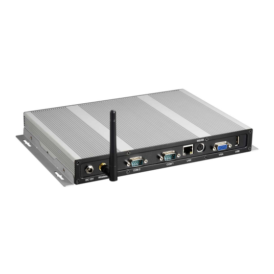
Page 28: Chapter 5 Interface
VGA Display Connector PS/2 KB/MS Mini-DIN Connector MS/KB Fast/ Gigabit Ethernet Connector RS-232 Port A DB-9 Connector COM1 COM2 RS-232/422/485 Port A DB-9 Connector Table 3 Rear panel connectors description Table 4 USB Connector pin definition QDSP-1000/ 1010 User’s Manual... -
Page 29: Table 5 Vga Display Connector Pin Definition
Chapter 5 Table 5 VGA Display Connector pin definition Table 6 Keyboard/Mouse Connector pin definition Table 7 Gigabit Ethernet Connector pin definition (QDSP-1010) Table 8 Fast Ethernet Connector pin definition (QDSP-1000) QDSP-1000/ 1010 User’s Manual... -
Page 30: Table 9 Com1 Rs-232 Serial Port Connector Pin Definition
Table 9 COM1 RS-232 Serial Port Connector pin definition Table 10 COM2 RS-232/ 422/ 485 Serial Port Connector pin definition Front I/O Panel Connector Function Surround Out LEF Out SIDE Out MIC In LINE In LINE Out Table 11 AC97’ Audio Connectors QDSP-1000/ 1010 User’s Manual... -
Page 31: Internal Jumpers
To ensure correct system configuration, the following section describes how to set the jumpers to enable/ disable or change functions. For jumper descriptions, please refer to the table below. Figure 11 Jumper Locations Table 12 CF Master/Slave Setting (JP2) Table 13 Clear CMOS Setting (JP3) QDSP-1000/ 1010 User’s Manual...