
Related Manuals for FIC AM35


Summary of Contents for FIC AM35
- Page 1 AM35 MAINBOARD MANUAL DOC No.: M01902 Rev. : A0 Date : 4, 2002 Part No. : 25-11635 -00...
- Page 2 ATA133 data transaction for hard drives and allows up to 2 GB memory totally by 2 PC1600/PC2100 DIMM sockets. The AM35 is based around the high performance V-link VIA ProSavageDDR KM266 core chip with VIA VT8233A as a South Bridge. The AGP(2X/4X) functions supported by KM266 provides you with a photo-realistic 3D expe- rience suitable for the most robust 3D games and software environments.
-
Page 3: Package Checklist
AM35 Mainboard Manual Package Checklist If you discover any item below was damaged or lost, please contact your vendor. The mainboard This user manual One FDD cable CD software One ATA100 cable IMPORTANT: AMD CPU HEAT SINK INSTALLATION Be ware finish heat sink install. Before you boot system, please check the heat sink is complete contact with die of CPU. - Page 4 Overview The AM35 Mainboard 1 - 3...
-
Page 5: Main Features
AM35 Mainboard Manual Main Features Easy Installation ||BIOS with support for Plug and Play, auto detection of IDE hard drives, ||LS-120|drives, IDE ZIP drives, Windows 98SE, Windows ME, Windows ||NT, Windows 2000, Windows XP, and OS/2. Leading Edge Chipset VIA KM266 is a single-chip North Bridge for AMD CPUs with 200/266 MHz Front Side Bus with AGP and PCI plus advanced memory controller that supports PC1600/PC2100 DDR SDRAM. - Page 6 Overview AGP and PCI Expansion Slots One AGP Bus and three PCI Bus expansion slots provided the room to install a full range of add-on cards. Compact Onboard Audio Subsystem Embeded in VIA VT8233A, an integrated high bandwidth Vlink client controller, direct sound AC97 audio subsystem.
-
Page 7: Fic Unique Innovation For Users (Novus)
AM35 Mainboard Manual FIC Unique Innovation for Users (NOVUS) - Enhanced Mainboard Features and System Support LogoGenie A user friendly GUI supporting Windows 95/98/98SE (not Windows 2000/ NT/ME), LogoGenie allows you to customize, create or select a Logo which will be displayed when the system is booting. - Page 8 Overview NOTE: However, if it is disabled and while boot the system, the POST screen will be held and shows you the message to let you know the current status of BIOS Guardian. To press G key will en- able the BIOS Guardian again; or simply to press the space bar will continue the booting process.
- Page 9 AM35 Mainboard Manual This Page Left Blank for Note 1 - 8...
-
Page 10: Installation Procedures
Installation Procedures Chapter 2 Installation Procedures The mainboard has several user-adjustable jumpers on the board that allow you to configure your system to suit your requirements. This chapter contains information on the various jumper settings on your mainboard. To set up your computer, you must complete the following steps: Step 1 - Set system jumpers Step 2 -... -
Page 11: Quick Reference (From Page 2-2 To 2-4)
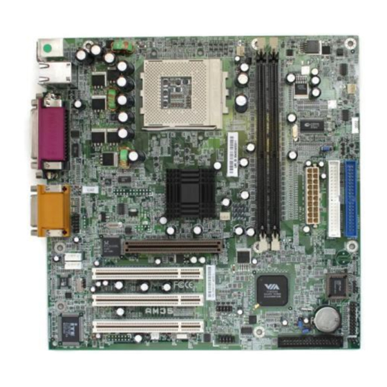
AM35 Mainboard Manual Quick Reference (from Page 2-2 to 2-4) Mainboard Layout * When link to Line_Out jack, please use a speaker that with amplifier. 2 - 2... - Page 12 Installation Procedures Clear CMOS, Clear Password, FSB Speed Select Front Panel Block Cable Connection 2 - 3...
-
Page 13: Set System Jumpers
AM35 Mainboard Manual CPU Fan Installation CAUTION: 1. The heatsink and fan you installed must be approved by AMD. 2. The mainboard must be placed on a solid place to avoid shaking |||||while install the heatsink and fan on the board. - Page 14 Installation Procedures Clear Password: CLP This jumper allows you to enable or disable the password configuration. You may need to enable it if you forget your password. To clear the password setting: (1) Turn off your computer (2) Place the jumper cap onto pinpair (3) Turn on your computer (4) Hold down the Delete key during bootup and enter BIOS Setup to clear password (5) Save the setting and exit (6) Turn off your computer.
-
Page 15: Install Memory Modules
AM35 Mainboard Manual FSB Frequency Select: FSB This jumper allows you to select the front side bus frequency of the board. 2). Install Memory Modules Locate the DIMM slots on the mainboard. Install the DIMM straight down into the DIMM slot using both hands. -
Page 16: Install The Cpu
Installation Procedures Press the clips with both hands to remove the DIMM. 3). Install the CPU The AMD CPU module resides in the socket on the board. Please follow the steps introduced below to complete the CPU installation. CAUTION: 1. The heat sink and fan you installed must be approved by AMD. 2. -
Page 17: Install Expansion Cards
AM35 Mainboard Manual To install the CPU, do the following: Lift the lever on the side of the CPU socket. Handle the chip by its edges and try not to touch any of the pins. Place the CPU in the socket. The chip has two notches to correctly locate the chip. - Page 18 Installation Procedures CAUTION: Make sure to unplug the power supply when adding or removing expansion cards or other system components. Failure to do so may cause severe damage to both the mainboard and expansioncards. Always observe static electricity precautions. Please read Handling Precautions at the start of this manual. To install an expansion card, follow the steps below: Remove the chassis cover and select an empty expansion slot.
-
Page 19: Connect Devices
AM35 Mainboard Manual 5). Connect Devices Floppy Diskette Drive Connector This connector provides the connection with your floppy disk drive. The red stripe of the ribbon cable must be the same side with the Pin 1. IDE Device Connectors The two connectors, PRIMARY and SECONDARY, are used for your IDE hard disk drives, CD drives, LS-120|drives, or IDE ZIP drives. -
Page 20: Atx Power Connector
Installation Procedures ATX Power Connector This 20-pin male block connector is connected to the ATX power supply. The plug from the power supply will only insert in one orientation because of the different hole sizes. Find the proper orientation and push down firmly making sure that the pins are aligned. -
Page 21: Wake-On-Ring Connector
AM35 Mainboard Manual Wake-On-Ring Connector The 2-pin connector allows you to link with your modem card which outputs a WOR singal; the system can be turned on from the power-off status by a remote phone call via the modem card. -
Page 22: Cd Audio-In Connectors
Installation Procedures CD Audio-In Connectors The CD_IN connector is used as a port for audio input from CD drive. The AUX_IN privided users with one extra audio input port from CD drive. Front Panel Block, Power LED and Speaker Connector This block connector includes the connectors for linking with HDD LED, power LED (2 and 3 pins), dual power LED, power button, suspend button, reset button, and IR on the front panel of the system case. - Page 23 AM35 Mainboard Manual NOTE: When a dual power LED is used, Pin 2 is for green one and Pin 4 is for yellow one. If single power LED installed, Pin 2 is for positive and Pin 4 is for negative.
-
Page 24: Ps/2 Keyboard And Mouse Connector
Installation Procedures PS/2 Keyboard and Mouse Connector These two 6-pin female (PS/2 keyboard is purple color and PS/2 mouse is green color) connectors are used for your PS/2 keyboard and PS/2 mouse. Game/MIDI Connector This 15-pin female gold-colored connector allows you to connect game joy- sticks or game pads. -
Page 25: Universal Serial Bus Connectors
AM35 Mainboard Manual Universal Serial Bus Connectors These two black jacks are integrated on the rear edge of the board for linking with USB devices. This board has a pinhead, USB2/3, for two extra USB ports that either on front or rear panel. -
Page 26: Printer Connector
Installation Procedures Printer Connector This 25-pin D-Sub female burgundy-colored connector is attached to your printer. Audio I/O Jacks LINE_OUT (lime) can be connected to headphones or preferably powered speakers. LINE_IN (light blue) allows tape players or other audio sources to be recorded by your computer or played through the LINE_OUT. -
Page 27: Lan Connector (Optional)
AM35 Mainboard Manual LAN Connector (optional) The optional LAN jack is connected to the LAN cable. 2 - 18... -
Page 28: Bios Setup
BIOS Setup Chapter 3 BIOS Setup The mainboard comes with the chip that Award BIOS that contains the ROM Setup information of your system. (This chip serves as an interface between the processor and the rest of the mainboard components.) This section ex- plains the information contained in the Setup program and tells you how to modify the settings according to your system configuration. -
Page 29: Standard Cmos Setup
AM35 Mainboard Manual Standard CMOS Setup The Standard CMOS Setup screen is displayed above. Each item may have one or more option settings. The system BIOS automatically detects memory size, thus no changes are necessary. Use the arrow keys to highlight the item and then use PgUp or PgDn keys to select the value you want in each item. - Page 30 BIOS Setup Hard Disks This field records the specifications for all non-SCSI hard drives installed in the system. The onboard PCI IDE connectors provide Primary and Sec- ondary channels for connecting up to four IDE hard disks or other IDE devices.
-
Page 31: Advanced Bios Features
AM35 Mainboard Manual Advanced BIOS Features Virus Warning This feature will prompt uses a warning message, when any write boot sector commend executed. The options are: Enabled, Disabled. CPU Internal Cache When enabled, improves the system performance. Disable this item when testing or trouble-shooting. - Page 32 BIOS Setup Hard Disk Boot Priority This feature will auto detect all hard disks of bootable device on the sys- tem. It also allows users to select hard disk device booting priority. First/Second/Third Boot Device This feature allows user to select the boot device priority. The options are: Floppy, LS120, Hard Disk, CDROM, ZIP100, USB-FDD, USB-ZIP, USB- CDROM, USB-HDD, LAN, Disabled.
- Page 33 AM35 Mainboard Manual Typematic Rate (Chars/Sec) This feature is available only if the above item, Typematic Rate Setting, is set at Enabled. Sets the rate of a character repeat when the key is held down. The options are: 6, 8, 10, 12, 15, 20, 24, 30.
-
Page 34: Advanced Chipset Features
BIOS Setup Video BIOS Shadow Enabling this feature will copy the video BIOS to shadow RAM, it will improve the system performance. The options are: Enabled, Disabled. Full Screen LOGO Show It decides whether or not the full screen logo is shown during system booting up. - Page 35 AM35 Mainboard Manual DRAM Clock The feature allows users to select the DRAM clock. The options are: 100 MHz, 133 MHz, Host CLK, By SPD. DRAM Timing This feature allows user to select the way to set DRAM timing. The options are: By SPD, Manual.
- Page 36 BIOS Setup AGP & P2P Bridge Control AGP Aperture Size It allows you to select the main memory frame size for AGP use. The options are: 256M, 128M, 64M, 32M, 16M, 8M, 4M. AGP Mode This feature allows users to select the AGP mode when an AGP add-on card installed.
- Page 37 AM35 Mainboard Manual PCI Delay Transaction Enable this feature to abort the current PCI master cycle and to accept the new PCI master request, it reaccepts the original PCI master and returns the PCI data phase to the original PCI master. The options are: Disabled, Enabled.
-
Page 38: Integrated Peripherals
BIOS Setup Integrated Peripherals VIA OnChip IDE Device OnChip IDE Channel0 When enabled, allows you to use the onboard primary PCI IDE. If a hard disk controller card is used, set at Disabled. The options are: Enabled, Disabled. OnChip IDE Channel1 When enabled, allows you to use the onboard secondary PCI IDE. - Page 39 AM35 Mainboard Manual Primary Master PIO Allows an automatic or a manual configuration of the PCI primary IDE hard disk (master) mode. The options are: Auto, Mode 0, Mode 1, Mode 2, Mode 3, Mode 4. Primary Slave PIO Allows an automatic or a manual configuration of the PCI primary IDE hard disk (slave) mode.
- Page 40 BIOS Setup VIA OnChip PCI Device VIA-3058 AC97 Audio It allows users to disable AC97 link in South Bridge. The options are: Auto, Disabled. VIA-3068 MC97 Modem It allows users to disable MC97 link in South Bridge. The options are: Auto, Disabled. SuperIO PCI Device Onboard FDC Controller When enabled, the floppy diskette drive (FDD) controller is activated.
- Page 41 AM35 Mainboard Manual Onboard Parallel Port Allows you to select from a given set of parameters if the parallel port uses the onboard I/O controller. The options are: Disabled, 378/IRQ7, 278/IRQ5, 3BC/IRQ7. Parallel Port Mode Allows you to connect with an advanced printer via the port mode it supports.
- Page 42 BIOS Setup USB Mouse Support When a USB mouse is installed, please set at Enabled. The options are: Disabled, Enabled. IDE HDD Block Mode When enabled, the system executes read/write requests to hard disk in block mode. The options are: Enabled, Disabled. Onboard Lan Device This feature allows users to enable or disable the onboard Lan device.
-
Page 43: Power Management Setup
AM35 Mainboard Manual Power Management Setup ACPI function This item allows you to disable the ACPI function. The options are: Enabled, Disabled. ACPI Suspend Type This item allows you to select ACPI suspend types. The options are: S1(POS), S3 (STR), S1&S3. - Page 44 BIOS Setup Suspend Mode When disabled, the system will not enter Suspend mode. The specified time option defines the idle time the system takes before it enters Suspend mode. The options are: Disable, 1, 2, 4, 6, 8, 10, 20, 30, 40 Min, 1 Hour. Video Off Option This feature provides the selections of the video display power saving mode.
- Page 45 AM35 Mainboard Manual IRQ/Event Activity Detect USB Resume From S3 When set at Enabled, it allows USB devices that linked with the system to activate the system from ACPI S3 power saving mode. The options are Disabled, Enabled. When set at On, any VGA activity will awake the system.
- Page 46 BIOS Setup Date (of Month) This feature allows you to set the day of the alarm starts when the RTC Alarm Resume From Soft Off is set to be Enabled. The options are: 0, 1..31. Resume Time (hh:mm:ss) If an ATX power supply is installed and when RTC Alarm Resume is En- abled, this feature allows you to set the time of the alarm starts when the RTC Alarm Resume From Soft Off is set to be Enabled.
-
Page 47: Pnp/Pci Configurations
AM35 Mainboard Manual PnP/PCI Configurations PNP OS Installed If your operating system is a Plug-and-Play one, such as Windows NT, Windows 95, select Yes. The options are: No, Yes. Reset Configuration Data Enabling it to reset the system Extended System Configuration Data (ESCD) -
Page 48: Pc Health Status
BIOS Setup Assign IRQ For VGA If your PCI VGA card devices do not need an IRQ, select Disabled; there- fore, an IRQ can be released for the system use. The options are: Enabled, Disabled. Assign IRQ For USB If your USB devices do not need an IRQ, select Disabled; therefore, an IRQ can be released for the system use. -
Page 49: Frequency/Voltage Control
AM35 Mainboard Manual Voltage VCORE / Voltage + 2.5 V / Voltage +3.3 V / Voltage +5 V / Voltage +12 V / Voltage 5VSB / Voltage Battery / SYSTEM Temp. / CPU Temp. / CPU FAN Speed / Chassis FAN Speed These items allow end users and technicians to monitor data provided by the BIOS on this mainboard. -
Page 50: Load Fail-Safe Defaults
BIOS Setup CPU Host/PCI Clock/3V66 This feature allows you to select the combinations of CPU, onboard de- vices (such as AGP bus, South Bridge) that runs with 66MHz frequency, and PCI clock frequency. The default setting, Default, will detect your CPU/PCI/3V66 clock frequency automatically. -
Page 51: Save And Exit Setup
AM35 Mainboard Manual Save and Exit Setup After you have made changes under Setup, press Esc to return to the main menu. Move cursor to Save and Exit Setup or press F10 and then press Y to change the CMOS Setup. If you did not change anything, press Esc again or move cursor to Exit Without Saving and press Y to retain the Setup settings.