
Related Manuals for Baxi Bermuda SP3


Summary of Contents for Baxi Bermuda SP3
- Page 1 Please leave these Instructions with the User. Baxi Bermuda SP3/VP3 Fireside Gas Central Heating Unit Installation and Servicing Instructions Supplied By www.heating spares.co Tel. 0161 620 6677...
- Page 2 Everyone who works at the company has a commitment to quality because, as shareholders, we know that satisfied customers mean continued success. We hope you get a satisfactory service from Baxi. If not, please let us know. Baxi is a BS-EN ISO 9001 Accredited Company...
- Page 3 Fitting the Fire Commissioning the Fire 16-18 PAGE Spillage Detection Fitting the Outer Case 19-20 PAGE Bermuda VP3 Bermuda SP3 Annual Servicing 21-25 PAGE Cleaning the Pilot / A.S.D. Assembly Cleaning the Burner / Injectors Changing Components 26-33 PAGE Glass Frame...
- Page 4 Information Codes of Practice, most recent version should be used Safe Installation In GB the following Codes of Practice apply: Standard Scope The appliance is suitable only for installation in GB and IE BS 6891 Gas Installation. and should be installed in accordance with the rules in force. BS 5546 Installation of hot water supplies for domestic purposes.
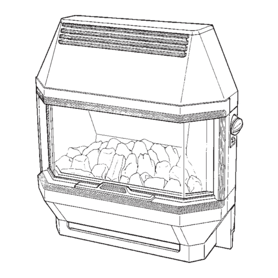
- Page 5 INTRODUCTION Description The Baxi Bermuda VP3 and Baxi Bermuda SP3 are combined gas fired central heating boiler and gas fire units, designed for installation in a living room. These boilers and fires are designed to be used on Natural Gas (For propane see page 35).
- Page 6 Thermocouple 9.4 - 13mV Depth 337mm Output Pilot Assembly 9401 Injector Heat Input (Gross) 210W (715 Btu/h) Bermuda SP3 (Natural Gas) 100mm Heat Input (Gross) High Med-High Gas Connection The gas supply is provided from the 76mm 5.74 4.95 service cock on the boiler unit.
- Page 7 SITE REQUIREMENTS 508mm Max Fireplace Opening 406mm Min The principal site requirements are determined by the boiler unit, but the following details are essential for the Fireplace correct installation of the fire unit: Opening 560mm Fireplace Opening: Height: 560mm (22in) Width: 406mm (16in) min 508mm (20in) max NOTE: Where possible the fireplace opening...
- Page 8 INSTALLATION Initial Preparation Unpack the fire unit by removing the polystyrene packing piece complete with fitments and placing to one side, then lift the fire from its box. Electrode Electrical Connections Plug Plug and Micro-Switch Socket - 3 pin Spark Generator Resistor br - Brown b - Blue...
- Page 9 Manual Control Models If the fire supply cable has not been fitted when wiring the boiler proceed as follows:- Isolate the electrical supply to the boiler including the permanent live. Remove the boiler controls assembly as described in the boiler Installation and Servicing Instructions.
- Page 10 From the plug and cable connection supplied with the fire unit, the following connections should be made, making sure that the appropriate cable clamp is used to hold the cable firmly. Connect the blue wire (neutral) to the remaining terminal marked ‘N’. Connect the brown wire (permanent live) to the remaining terminal marked ‘L2’.
- Page 11 Electronic Controls Models Remove the controls heat shield from its retaining clips. Controls Heat Shield Isolate the electrical supply to the boiler, including the permanent live. Remove the electrical inlet socket from the PCB at the rear left hand side of the control box. Remove the socket cover.
- Page 12 Electronic Controls Model (51/5 only) 3 Pin Electrical Plug 4 Pin Electrical Inlet Socket Remove the controls heat shield from its retaining clips. Isolate the electrical supply to the boiler, including the permanent live. Remove the electrical inlet socket from the PCB at the rear left hand side of the control box.
- Page 13 Gas Supply The gas installation should be in accordance with relevant standards. In GB this is BS 6891. In IE this is I.S. 813 “ Domestic Gas Installations”. The gas supply to the fire unit is provided from the gas service cock on the boiler using the supply pipe supplied with the unit.
- Page 14 Drill the fixing holes in the surround/wall face to accept suitable wall plugs. Fix the backing plate in position on the wall using suitable screws. NOTE: (For Bermuda SP3 only) Fit the two blanking plates in position using the in screws provided. Blanking Plate...
- Page 15 Drill the fixing holes in the surround/wall face to accept suitable wall plugs. Fix the backing plate in position on the wall using suitable screws. NOTE: (For Bermuda SP3 only) Fit the two blanking plates in position using the in screws provided.
- Page 16 COMMISSIONING THE FIRE Turn the gas service cock to the boiler and fire position. Purge according to in GB BS 6891 and in IE the current edition of I.S. 813 “Domestic Gas Installations”. (Manual Controls Boiler shown) Boiler/Fire Remove the glass frame by disengaging the retaining clamps and lifting away.
- Page 17 Check the electricity supply to the fire unit by switching on the illumination bulbs. If the bulbs light, switch off and continue with commissioning the fire. If the bulbs do not light, isolate the electricity supply and perform preliminary electrical system checks before proceeding i.e.
- Page 18 Check the setting pressure at position 4. No adjustment to the setting pressure is possible. Turn the control knob to the ‘OFF’ ( ) position. Disconnect the pressure gauge and replace the pressure test point sealing screw, ensuring a gas- tight seal.
- Page 19 FITTING THE OUTER CASE Bermuda VP3 Turn off the fire and fit the outer case components as follows: Remove the fender front from the hearth assembly by pulling forward. Engage the hearth assembly on the side ledges as shown and push home as far as possible.
- Page 20 Bermuda SP3 Turn off the fire and fit the outer case components as follows: Locating Engage the hearth by guiding the locating pins through the holes in the innercase and sliding forward on the side ledges as far as possible. Fix the hearth in...
- Page 21 ANNUAL SERVICING Bermuda VP3 For reasons of safety and economy, it is important to service both the fire and boiler units annually. Before servicing please read the Important Information section on page 5. NOTE: Before attempting to service the appliance, ensure that the fire is COLD. Important: It is possible that some soot may be deposited on the coals after use.
- Page 22 Bermuda SP3 For reasons of safety and economy, it is important to service both the fire and boiler units annually. Before servicing please read the Important Information section on page 5. NOTE: Before attempting to service the appliance, ensure that the fire is COLD.
- Page 23 In order to service the boiler unit, the fire must be disconnected and removed at this point. Once disconnected the fire unit may be serviced separately from the boiler. Disconnect the 3-pin plug from the socket beneath the fire. Turn off the gas service cock by turning fully clockwise.
- Page 24 2.5 - 4.0mm. The thermocouple cannot be changed as an individual component. The complete assembly must be replaced in the event of one or other component failure(s). Only use a Genuine Baxi Spare Part. Supplied By www.heating spares.co Tel. 0161 620 6677...
- Page 25 Cleaning the Burner / Injectors Remove the burner as follows: Remove the locating pins (these also secure the burner to its support brackets). Disconnect the compression nuts from the injectors. Remove the burner from the fire. Using a soft brush remove any dirt or debris from the top of the burner and ensure that the ports and aeration openings are free from obstruction.
- Page 26 CHANGING COMPONENTS Bermuda VP3 When changing components ensure that the gas and electricity supplies (including the permanent live) are isolated before the work is started. Before changing any components please read the Important Information section on page 5. After changing components, check for gas leaks and recommission.
- Page 27 Bermuda SP3 When changing components ensure that the gas and electricity supplies (including the permanent live) are isolated before the work is started. Before changing any components please read the Important Information section on page 5. After changing components, check for gas leaks and recommission.
- Page 28 Check that the seal between the rope and the glass frame is good. Coal Bed Bermuda SP3 showing hearth in position Bermuda VP3 Ensure that the glass panel is showing hearth in position cold.
- Page 29 Burner and Injectors Ensure that the glass panel is cold. Disengage the retaining clamps and lift the frame away. Lift the coal bed away from the locating pins and place to one side. Remove the locating pins securing the burner to its support brackets.
- Page 30 Light Switch Ensure that the electricity supply to the fire unit is isolated. Bermuda VP3 showing hearth in position Remove the control knob by pulling from the spindle. Remove the two screws holding the bezel in place. Note the orientation of the two electrical connections and disconnect from the switch.
- Page 31 Electrode Lead Remove the insulating sleeve from the body of the electrode. Disconnect the electrode lead from the electrode. Disconnect the electrode lead from the spark generator. Undo the screw holding the orange panel to the chassis. Lift the panel upwards and withdraw the sleeve and lead.
- Page 32 The thermocouple cannot be changed as an individual component. The complete assembly must be replaced in the event of one or other component failure(s). Only use a Genuine Baxi Spare Part. Remove the lead from the electrode. Undo the pilot feed pipe from the assembly.
- Page 33 Control Tap and Micro-Switch Remove the control knob by pulling from the spindle. Remove the two screws holding the bezel in place. Disconnect the two electrical connections from the light switch, taking note of their orientation. Remove the bezel. Release the thermocouple from the control tap by unscrewing the retaining nut.
- Page 34 The thermocouple cannot be changed as an individual component.The complete assembly must be replaced in the event of one or other component failure(s). Only use a Genuine Baxi Spare Part. Spark Gap Supplied By www.heating spares.co Tel. 0161 620 6677...
- Page 35 Does both bulbs Fire satisfactory the fire remain light ? alight ? gas cocks fully Open gas cocks Does one open ? Replace faulty bulb bulb light? meter pressure Contact the Gas Supplier correct ? Are bulbs Switch on bulbs switched on ? Pipework supply pressure...
- Page 36 SHORT PARTS LIST 69/71 79/81 Key N G.C. Description Manufacturers Part N 156 036 Glass and Frame Assy 225391 156 233 Knob Control SP3 233466 46/48 156 431 Knob Control VP3 236394 156 063 Seal Frame Glass Rope 226876 378 912 Pilot/A.S.D.
- Page 37 12,385 Supply Pressure mbar Propane appliances can be converted to operate on in wg 14.8 Natural Gas if required. A conversion kit is available, Baxi Part No 247064. Setting Pressure Cold 34.2 + 1.5 mbar 13.7 + 0.6 in wg...
- Page 38 Controls Heat Shield necessary components to fit a Baxi Bermuda VP3 Renewal & Baxi Bermuda SP3 Renewal firefront to the following Bermuda Boilers. NOTE: It is important at this stage to fit the controls heat shield supplied with the fire unit to The Renewal Fires may be used with the following the boiler front panel.
- Page 39 If the fire is wall mounted remove and discard the existing support frame (Bermuda 401 only). Retain the two support brackets. These will be needed in wall mounting the renewal fire. If the fire is hearth mounted ensure that the base of the builders opening and the front hearth are at the same level.
- Page 40 B A X I P O T T E R T O N Brownedge Road Bamber Bridge Preston Lancashire PR5 6SN After Sales Service 08706 096 096 Technical Enquiries 08706 049 049 www.baxi.co.uk Comp N 237568 - Iss 9 - 1/03...