
Related Manuals for Miller Electric 22A


Summary of Contents for Miller Electric 22A
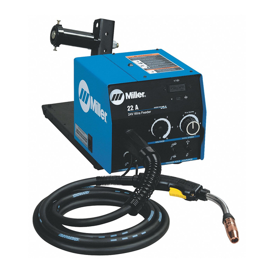
- Page 1 Visit our website at www.MillerWelds.com 22A, 24A OM-193 472N 2006−05 Processes MIG (GMAW) Welding Flux Cored (FCAW) Welding Description Wire Feeder File: MIG (GMAW)
- Page 2 ISO 9001:2000 Quality System Standard. particular model are also provided. Miller Electric manufactures a full line of welders and welding related equipment. For information on other quality Miller products, contact your local Miller distributor to receive the latest full line catalog or individual specification sheets.
-
Page 3: Table Of Contents
TABLE OF CONTENTS SECTION 1 − SAFETY PRECAUTIONS - READ BEFORE USING 1-1. Symbol Usage ............... . 1-2. -
Page 5: Section 1 − Safety Precautions - Read Before Using
DC constant voltage (wire) welder, 2) a DC manual (stick) welder, or 3) an AC welder with reduced open-circuit volt- age. In most situations, use of a DC, constant voltage wire welder is recommended. And, do not work alone! D Disconnect input power or stop engine before installing or servicing this equipment. - Page 6 D Do not use welder to thaw frozen pipes. D Remove stick electrode from holder or cut off welding wire at contact tip when not in use.
-
Page 7: Additional Symbols For Installation, Operation, And Maintenance
1-3. Additional Symbols For Installation, Operation, And Maintenance FIRE OR EXPLOSION hazard. D Do not install or place unit on, over, or near combustible surfaces. D Do not install unit near flammables. D Do not overload building wiring − be sure power supply system is properly sized, rated, and protected to handle this unit. -
Page 8: Principal Safety Standards
1-5. Principal Safety Standards Safety in Welding, Cutting, and Allied Processes, ANSI Standard Z49.1, from Global Engineering Documents (phone: 1-877-413-5184, website: www.global.ihs.com). Recommended Safe Practices for the Preparation for Welding and Cut- ting of Containers and Piping, American Welding Society Standard F4.1 from Global... -
Page 9: Section 2 − Consignes De Sécurité − Lire Avant Utilisation
SECTION 2 − CONSIGNES DE SÉCURITÉ − LIRE AVANT UTILISATION Y Avertissement : se protéger et protéger les autres contre le risque de blessure — lire et respecter ces consignes. 2-1. Symboles utilisés Symbole graphique d’avertissement ! Attention ! Cette pro- cédure comporte des risques possibles ! Les dangers éven- tuels sont représentés par les symboles graphiques joints. - Page 10 LES RAYONS D’ARC peuvent entraî- ner des brûlures aux yeux et à la peau. Le rayonnement de l’arc du procédé de soudage génère des rayons visibles et invisibles intenses (ultraviolets et infrarouges) susceptibles de provo- quer des brûlures dans les yeux et sur la peau. Des étincelles sont projetées pendant le soudage.
-
Page 11: Dangers Supplémentaires En Relation Avec L'installation, Le Fonctionnement Et La Maintenance
2-3. Dangers supplémentaires en relation avec l’installation, le fonctionnement et la maintenance Risque D’INCENDIE OU D’EXPLO- SION. D Ne pas placer l’appareil sur, au-dessus ou à proximité de surfaces inflammables. D Ne pas installer l’appareil à proximité de produits inflammables. D Ne pas surcharger l’installation électrique −... -
Page 12: Principales Normes De Sécurité
2-5. Principales normes de sécurité Safety in Welding, Cutting, and Allied Processes, ANSI Standard Z49.1, de Global Engineering Documents (téléphone : 1-877-413-5184, site In- ternet : www.global.ihs.com). Recommended Safe Practices for the Preparation for Welding and Cut- ting of Containers and Piping, American Welding Society Standard AWS F4.1 de Global Engineering Documents (téléphone : 1-877-413-5184, site Internet : www.global.ihs.com). -
Page 13: Section 3 − Installation
SECTION 3 − INSTALLATION 3-1. Specifications Type of Input Welding Power Power Source Type 24 Volts AC Single Constant Voltage Phase (CV) DC With 7 Amperes 50/60 14-Pin And Contactor Control 3-2. Site Selection Wire Wire Feed Diameter Speed Range Circuit Rating Range .023 To 5/64 in... -
Page 14: Gun Recommendation Table
3-3. Gun Recommendation Table Process GMAW − Hard or Corded Wires FCAW − Self-Shielding Wires 3-4. Equipment Connection Diagrams 3-5. 14-Pin Plug, Shielding Gas And Optional Volt Sense Lead Tools Needed: 5/8, 11/16 in OM-193 472 Page 10 M25 Or M40 GA-40GL 115VAC Contactor... -
Page 15: 14-Pin Plug Information
3-6. 14-Pin Plug Information Pin* *The remaining pins are not used. 3-7. Connecting Welding Gun And Weld Cable Pin Information 24 volts ac with respect to pin G. Contact closure to A completes 24 volts ac contactor control circuit. Circuit common for 24 volts AC circuit. +10 volts dc output to remote control with respect to pin D. -
Page 16: Optional Meter Circuit Board Settings
3-8. Optional Meter Circuit Board Settings X Means switch position does not affect specified function. Means switch must be in this position. Voltage Sensing Function Arc Voltage Sensing Using Voltage Sensing Lead For Welding Power Source That Does Not Support Pins F And H Arc Voltage Sensing Using Feedback From Welding Power Source That Does Support Tools Needed:... -
Page 17: Motor Start/Burnback Control
3-9. Motor Start/Burnback Control Tools Needed: Non-Conductive 1/4 in To change wire feed starting speed proceed as follows: Turn Off unit and welding power source. Remove wrapper. Motor Board PC1 Motor Start Control Potentiometer R73 Remove protective white rubber cap before making adjustment. Adjust potentiometer R73 using a small nonconductive screwdriver. -
Page 18: Installing Wire Guide And Drive Roll
3-10. Installing Wire Guide And Drive Roll Install and secure inlet wire guide either assembly, intermediate wire guide on 4 drive roll assembly only. Install drive rolls and turn drive roll nut one click. During maintenance intervals, remove drive rolls, and clean grooves using a wire brush. -
Page 19: Installing And Threading Welding Wire
3-11. Installing And Threading Welding Wire Tighten WOOD Retaining Ring Hub Tension Adjustment Nut If necessary, move hub on support for use of different size wire spool. Remove retaining ring, and install spool so hub pin fits spool hole. Reinstall retaining ring. Adjust tension nut so wire is taut when wire feed stops. -
Page 20: Section 4 − Operation
SECTION 4 − OPERATION 4-1. Front Panel Controls OM-193 472 Page 16 Optional Voltage/Wire Speed Meter Optional Voltage/Wire Speed Switch Use to choose volts or wire feed speed display. Optional Remote Voltage Control Use to set welding power source voltage at the wire feeder. Numbers are for reference only. -
Page 21: Optional Side Panel Controls
4-2. Optional Side Panel Controls SECTION 5 − MAINTENANCE & TROUBLESHOOTING 5-1. Routine Maintenance Replace Unreadable Labels 14-Pin Cord Y Disconnect power before maintaining. 3 Months Repair Or Replace Cracked Weld Cable Gun Cable Gas Hose 6 Months Clean Drive Rolls Preflow Control Control sets time gas flows before... -
Page 22: Overload Protection
5-2. Overload Protection 5-3. Troubleshooting Trouble Wire does not feed, unit completely inop- Turn Power switch On. erative. Check 14−pin plug PLG2 connections. Check input power. Wire does not feed. Check circuit breaker CB1. (see Section 5-2) Check gun trigger connection at wire feeder. Check gun trigger leads and trigger switch. See gun Owner’s Manual. -
Page 23: Section 6 − Electrical Diagram
SECTION 6 − ELECTRICAL DIAGRAM 210 430-A Figure 6-1. Circuit Diagram For Wire Feeder With Optional Equipment OM-193 472 Page 19... -
Page 24: Section 7 − Parts List
SECTION 7 − PARTS LIST Figure 7-2 & Figure 7-3 OM-193 472 Page 20 Figure 7.1. Main Assembly Hardware is common and not available unless listed. 802 358-F... - Page 25 Item Diagram Part marking ....089 899 ....+198 650 .
- Page 26 +When ordering a component originally displaying a precautionary label, the label should also be ordered. OPTIONAL OPTIONAL IN 22A, STANDARD IN 24A To maintain the factory original performance of your equipment, use only Manufacturer’s Suggested Replacement Parts. Model and serial number required when ordering parts from your local distributor.
- Page 27 Item Diagram Part marking ....602 009 ....172 075 .
- Page 28 Item Diagram Part marking ....602 009 ....172 075 .
- Page 29 Table 7-1. Drive Roll And Wire Guide Kits (2 Drive Roll) NOTE Base selection of drive rolls upon the following recommended usages: 1. V-Grooved rolls for hard wire. 2. U-Grooved rolls for soft and soft shelled cored wires. 3. U-Cogged rolls for extremely soft shelled wires (usually hard surfacing types). 4.
- Page 30 Table 7-2. Drive Roll & Wire Guide Kits (4 Drive Roll) NOTE Base selection of drive rolls upon the following recommended usages: 1. V-Grooved rolls for hard wire. 2. U-Grooved rolls for soft and soft shelled cored wires. 3. U-Cogged rolls for extremely soft shelled wires (usually hard surfacing types). 4.
- Page 31 Warranty Questions? LIMITED WARRANTY − Subject to the terms and conditions Call below, Miller Electric Mfg. Co., Appleton, Wisconsin, warrants to 1-800-4-A-MILLER its original retail purchaser that new Miller equipment sold after the effective date of this limited warranty is free of defects in for your local material and workmanship at the time it is shipped by Miller.
-
Page 32: Options And Accessories
File a claim for loss or damage during shipment. For assistance in filing or settling claims, contact your distributor and/or equipment manufacturer’s Transportation Department. 2006 Miller Electric Mfg. Co. 2006−01 Miller Electric Mfg. Co. An Illinois Tool Works Company 1635 West Spencer Street Appleton, WI 54914 USA International Headquarters−USA...