Table of Contents
Advertisement
Quick Links
Advertisement
Table of Contents

Related Manuals for Asus TS300-E3


Summary of Contents for Asus TS300-E3
- Page 2 ASUSTeK COMPUTER INC. (“ASUS”). ASUS provides this manual “as is” without warranty of any kind, either express or implied, including but not limited to the implied warranties or conditions of merchantability or fitness for a particular purpose. In no event shall ASUS, its directors, officers, employees, or agents be liable for any indirect, special, incidental,...
-
Page 3: Table Of Contents
Contents Notices ... vii Safety information ... viii About this guide ... ix Chapter 1: Product introduction System package contents ... 1-2 System specifications ... 1-3 System specifications ... 1-4 Front panel features ... 1-5 Rear panel features ... 1-6 Internal features ... - Page 4 Managing and updating your BIOS ... 5-2 5.1.1 Creating a bootable floppy disk ... 5-2 5.1.2 AFUDOS utility ... 5-3 5.1.3 ASUS CrashFree BIOS 2 utility ... 5-6 5.1.4 ASUS Update utility ... 5-8 BIOS setup program ... 5-11 5.2.1 BIOS menu screen ... 5-12 5.2.2...
- Page 5 Contents Main menu ... 5-14 5.3.1 System Time ... 5-14 5.3.2 System Date ... 5-14 5.3.3 Legacy Diskette A ... 5-14 5.3.4 IDE Configuration ... 5-15 5.3.5 Primary, Secondary, Third, Fourth IDE Master/Slave ... 5-16 5.3.6 System Information ... 5-18 Advanced menu ...
- Page 6 Contents 6.2.7 Deleting a RAID configuration ... 6-28 6.2.8 Selecting the boot drive from a RAID set ... 6-29 6.2.9 Enabling the WriteCache ... 6-30 Global Array Manager ... 6-30 Adaptec SCSISelect(TM) Utility! (P5MT-S model only) ... 6-31 6.4.1 Configuring the SCSI controller ... 6-32 6.4.2 Enabling the HostRAID controller ...
-
Page 7: Notices
Notices Federal Communications Commission Statement This device complies with Part 15 of the FCC Rules. Operation is subject to the following two conditions: • This device may not cause harmful interference, and • This device must accept any interference received including interference that may cause undesired operation. -
Page 8: Safety Information
Safety information Electrical Safety • Before installing or removing signal cables, ensure that the power cables for the system unit and all attached devices are unplugged. • To prevent electrical shock hazard, disconnect the power cable from the electrical outlet before relocating the system. •... -
Page 9: About This Guide
About this guide Audience This user guide is intended for system integrators and experienced users with at least basic knowledge of configuring a server. Contents This guide contains the following parts: Chapter 1: Product Introduction This chapter describes the general features of the server, including sections on front panel and rear panel specifications. - Page 10 IMPORTANT: Instructions that you MUST follow to complete a task. NOTE: Tips and information to aid in completing a task. Reference Visit the ASUS websites worldwide that provide updated information for all ASUS hardware and software products. Refer to the ASUS contact information for details.
- Page 11 ASUS TS300-E3/PA4 & PS4...
-
Page 12: Chapter 1: Product Introduction
System package contents Check your ASUS TS300-E3 package with the items on the following table. The package contents vary for the following configurations: • (four hot-swap Serial ATA hard disk drives) • (four hot-swap SCSI hard disk drives) Item description ASUS TS300-E3 5U rackmount chassis with: •... -
Page 13: System Specifications
System specifications The ASUS TS300-E3 is a barebone server system featuring the ASUS P5MT Series motherboard. The server supports an Intel processor in the 775-land package, and includes the latest technologies through the chipsets embedded on the motherboard. Chassis Pedestal or rackmount 5U with removable front door bezel... -
Page 14: System Specifications
1 x PCI-X 100 MHz/64-bit slot (supports ZCR, PCI-X 1.0)* (colored green on PS4 model) 1 x PCI Express™ x16 slot (x8 Link)** 1 x Mini-PCI socket for the ASUS Server Management Board 1 x 3.25-inch FDD bay 3 x 5.25-inch drive bays 2 x USB 2.0 ports... -
Page 15: Front Panel Features
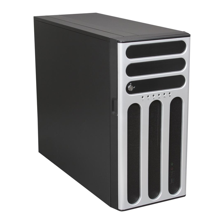
Front panel features The TS300-E3 chassis displays a stylish front bezel with lock. The bezel covers the system components on the front panel and serves as security. Open the bezel to access the front panel components. The drive bays, power and reset buttons, LED indicators, CD-ROM drive, floppy drive, and USB 2.0 ports are... -
Page 16: Rear Panel Features
Rear panel features The rear panel includes a slot for the motherboard rear I/O ports, expansion slots, a chassis lock and intrusion switch, a vent for the system fan, and power supply module. Power supply module Power connector PS/2 mouse port PS/2 keyboard port USB 2.0 ports Serial port... -
Page 17: Internal Features
Internal features The barebone server system includes the basic components as shown. The photo below shows the TS300-E3 with the hard disk drive blower installed. The HDD blower circulates cool air within the system. PA4 (4 hot-swap SATA configuration) •... - Page 18 • • • • • • Power supply unit Chassis fan ASUS P5MT-S motherboard Chassis intrusion switch Expansion card locks Optical drive 2 x 5.25-inch drive bays HDD blower (HDD drive cage inside) Front I/0 board 10. SCSI backplane •...
-
Page 19: Led Information
Drive Activity LED *SCSI Access Fault-Tolerant Enclosure (on PS4 model only) The Power, HDD Access, and Message LEDs are visible even if the system front bezel is closed. ASUS TS300-E3/PA4 & PS4 Power LED (blue) HDD Access LED (green) Message LED (red) - Page 20 1-10 Chapter 1: Product introduction...
- Page 21 ASUS TS300-E3/PA4 & PS4...
-
Page 22: Chapter 2: Hardware Setup
Chassis cover The chassis features a “screwless design” that allows convenient assembly and disassembly. You can simply push or slide mechanical bolts and locks to remove the cover. 2.1.1 Removing the side cover Remove the two screws that secure the cover to the chassis. Slide the side cover for about half an inch toward the rear until it is disengaged from the chassis. -
Page 23: Reinstalling The Side Cover
Slide the cover toward the front until it snaps in place. Drive in the two screws you removed earlier to secure the side cover. ASUS TS300-E3/PA4 & PS4... -
Page 24: Motherboard Overview
Motherboard overview The barebone server comes with the P5MT (PA4 model) or P5MT-S (PS4 model) motherboard already installed. The motherboard is secured to the chassis by nine (9) screws as indicated by the circles in the illustration below. Refer to “Chapter 4 Motherboard information” for detailed information on the motherboard. -
Page 25: Central Processing Unit (Cpu)
Retention tab Load lever To prevent damage to the socket pins, do not remove the PnP cap unless you are installing a CPU. ASUS TS300-E3/PA4 & PS4 PnP cap This side of the socket box should face you. - Page 26 Lift the load lever in the direction of the arrow to a 135º angle. Lift the load plate with your thumb and forefinger to a 100º angle (A), then push the PnP cap from the load plate window to remove (B). Position the CPU over the socket, making sure that the gold triangle is...
- Page 27 The motherboard supports Intel Intel Enhanced Memory 64 Technology (EM64T), Enhanced Intel SpeedStep ® Technology (EIST), and Hyper-Threading Technology. Refer to the Appendix for more information on these CPU features. ASUS TS300-E3/PA4 & PS4 Pentium 4 LGA775 processors with the ® ® ®...
-
Page 28: Installing The Cpu Heatsink And Airduct Assembly
Installing the CPU heatsink and airduct assembly The TS300-E3 comes with a proprietary CPU heatsink and airduct, which come in separate boxes when you receive the package. You have to assemble the CPU heatsink and airduct before installing to the motherboard. - Page 29 CPU, making sure that the heatsink screws match the screw holes on the motherboard. Drive the four screws into the holes in a diagonal sequence to secure the heatsink and airduct assembly to the motherboard. ASUS TS300-E3/PA4 & PS4...
-
Page 30: System Memory
• Always install DIMMs with the same CAS latency. For optimum compatibility, it is recommended that you obtain memory modules from the same vendor. Refer to the DDR2 Qualified Vendors List at the ASUS web site. • When installing one or two DIMMs, install the DIMM(s) to the blue slots (DIMM_A2/DIMM_B2). -
Page 31: Installing A Dimm
Support the DIMM lightly with your fingers when pressing the retaining clips. The DIMM might get damaged when it flips out with extra force. Remove the DIMM from the socket. ASUS TS300-E3/PA4 & PS4 DDR2 DIMM notch Unlocked retaining clip DDR2 DIMM notch 2-11... -
Page 32: Front Panel Assembly
Front panel assembly 2.5.1 Removing the front panel assembly Before you can install a 5.25-inch drive, you should first remove the front panel assembly (front bezel and front panel cover). The front panel assembly is attached to the chassis through three hooked tabs on the left side and four hinge-like tabs on the right side. - Page 33 Unhook the hinge-like tabs from the holes on the right side of the front panel to completely detach the front panel assembly from the chassis. Do not use too much force when removing the front panel assembly. ASUS TS300-E3/PA4 & PS4 Hinge-like tab 2-13...
-
Page 34: Reinstalling The Front Panel Assembly
2.5.2 Reinstalling the front panel assembly To reinstall the front panel assembly (front bezel and front panel cover): Insert the four hinge-like tabs to the holes on the right edge of the chassis. Swing the front panel to the left and fit the four (4) hooked tabs to the left side of the chassis until the tabs snap back in place. -
Page 35: 5.25-Inch Drives
To install a 5.25-inch drive: Use a Phillips (cross) screwdriver to remove the screws that secure the metal cover of the bay where you want to install the drive. Insert the optical drive into the 5.25-inch drive bay. ASUS TS300-E3/PA4 & PS4 2-15... - Page 36 Make sure that the drive and bay hole align as shown. When in place, the drive protrudes about an inch from the front panel. Secure the drive with a screw. Connect the IDE cable to the IDE connector on the back of the drive. Connect a 4-pin plug from the power supply to the power connector on the back of the drive.
- Page 37 5.25-inch drive that you installed by pressing the two hooked tabs on each side of the bay cover. Reinstall the front panel assembly when done. Refer to section “2.5.2 Reinstalling the front panel assembly” for instructions. ASUS TS300-E3/PA4 & PS4 2-17...
-
Page 38: Hard Disk Drives
Hard disk drives 2.7.1 Installing a hot-swap SATA/SCSI HDD Follow the instructions in this section to install a hot-swap SATA (PA4 model) or SCSI (PS4 model) hard disk drive (HDD). Open the front bezel to access the hot-swap drive trays. Release a drive tray by pushing the spring lock to the right, then pulling the tray lever outward. - Page 39 7. Push the tray lever until it clicks, and secures the drive tray in place. The drive tray is correctly placed when its front edge aligns with the bay edge. ASUS TS300-E3/PA4 & PS4 2-19...
-
Page 40: Installing An Hdd Dummy Cover
2.7.2 Installing an HDD dummy cover The HDD dummy covers come pre-installed on the front panel bezel. In case you removed the covers, follow these steps to re-install them. To install an HDD dummy cover: From the inside of the front panel assembly, insert the flat end of a dummy cover into the slot as shown. -
Page 41: Expansion Cards
Press the card firmly until it is properly seated on the slot. Secure the card to the chassis with the bracket screw you removed earlier. ASUS TS300-E3/PA4 & PS4 2-21... -
Page 42: Removing An Expansion Card
2.8.2 Removing an expansion card To remove an expansion card: Remove the screw that secures the card to the chassis. Carefully remove the card from the slot. Reinstall the metal bracket and secure it to the chassis with the screw that you removed earlier. 2-22 Chapter 2: Hardware setup... -
Page 43: Cable Connections
RECOVERY1 BMCCONN1 Standard cables connected to the motherboard 24-pin ATX power 4-pin 12V power CPU fan 1/2 Rear fan 1/2 Front fan 1/2 Serial ATA connectors ASUS TS300-E3/PA4 & PS4 25cm (9.8in) ATXPWR1 CPU_FAN1 ATX12V1 CPU_FAN2 Intel E7230 FM_CPU2 DDR2 DIMM_A1 (64 bit,240-pin module) -
Page 44: Sata Backplane Connections
SATA backplane connections (in PA4 model only) A SATA backplane comes pre-installed in the TS300-E3 PA4 model. The SATA backplane has four 15-pin SATA connectors to support Serial ATA hard disk drives. The backplane design incorporates a hot swap feature to allow easy connection or removal of SATA hard disks. -
Page 45: Back Side
CPU_FAN2 VGA1 LAN1 LAN2 LAN2 Broadcom BCM5721 Broadcom BCM5721 RAGE XL Controller 8Mbit Flash BIOS RECOVERY1 BMCCONN1 ASUS TS300-E3/PA4 & PS4 (for HDD fan) Backplane CON2 CON4 CON6 CON8 25cm (9.8in) ATXPWR1 FM_CPU1 ATX12V1 CPU_FAN1 LGA775 Intel E7230 FM_CPU2 DDR2 DIMM_A1 (64 bit,240-pin module) - Page 46 SATA backplane jumper settings and HDD ID assignments The 6-pin jumper J3 allows you to define your desired SATA configuration. The picture below shows the location of jumper J3 with pins 1-3 and 2-4 shorted. Refer to the table for the jumper settings and the appropriate ID# for each SATA HDD bay.
-
Page 47: Scsi Backplane Connections
SCSI backplane connections (in PS4 model only) A SCSI backplane comes pre-installed in the TS300-E3 PS4 model. The SCSI backplane has four 68-pin SCSI connectors to support SCA SCSI hard disks. The backplane design incorporates a hot swap feature to allow easy connection or removal of SCSI hard disks. - Page 48 Back side The back side of SCSI backplane faces the rear panel when installed. This side includes the power connectors, SCSI interfaces for the motherboard SCSI connector or the SCSI/RAID card and terminator, an HDD fan connector, and SMBus connectors. •...
- Page 49 Refer to the following tables for the jumper settings and the appropriate ID# for each SCSI HDD bay. J1 setting (1-3 shorted, 2-4 shorted) Device Drive Bay 1 Drive Bay 2 Drive Bay 3 Drive Bay 4 GEM SAF-TE ASUS TS300-E3/PA4 & PS4 SCSI ID# ID15 (SCSI channel-0) 2-29...
-
Page 50: 2.10 Removable Components
2.10 Removable components You may need to remove previously installed system components when installing or removing system devices, or when you need to replace defective components. This section tells how to remove the following components: Chassis fan HDD blowers SATA/SCSI backplanes Floppy disk drive module 2.10.1 Chassis fan... - Page 51 Align the chassis fan holes to the screw holes on the chassis. Drive in the four screws you removed earlier to secure the fan to the chassis. ASUS TS300-E3/PA4 & PS4 2-31...
-
Page 52: Hdd Blower
Plug the chassis fan cable to the connector on the motherboard. 2.10.2 HDD blower To remove the HDD blower: Remove the side cover. Refer to section “2.1.1 Removing the side cover” for instructions. Disconnect the 3-pin fan cable from the fan connector on the backplane. Loosen the thumb screw that secures the HDD blower case to the chassis. - Page 53 Set the screws aside. Remove the blower from the case. To reinstall the HDD blower: Replace the blower into the case. Secure the blower to the case with the two screws you removed earlier. ASUS TS300-E3/PA4 & PS4 2-33...
- Page 54 Slide in the blower case as shown, making sure the tabs fit into the holes on the HDD cage. Drive in the thumb screw to secure the HDD blower case. Connect the 3-pin fan cable to the fan connector on the backplane. 2-34 Chapter 2: Hardware setup...
-
Page 55: Sata/Scsi Backplane
Doing so may damage the cable! From the inner edge, push the backplane outward so that the outer edge protrudes slightly from the slot. From the outer edge, firmly hold the backplane and carefully slide it out. ASUS TS300-E3/PA4 & PS4 2-35... - Page 56 To reinstall a SATA/SCSI backplane: Position the backplane into its slot with the component side facing the rear panel, and the power connectors on top. Align the backplane with the rail- like dents on the slot to ensure that it fits securely. Slide the backplane into the slot until it fits.
-
Page 57: Floppy Disk Drive
Carefully pull out the drive from the chassis until you see the cables connected to the drive. Disconnect the floppy disk cable and power cable from the drive to completely release the drive. ASUS TS300-E3/PA4 & PS4 2-37... - Page 58 To install a floppy disk drive: Position the floppy drive vertically with the eject button on the left side (close to the HDDs). Connect the drive signal cable and power cable. Carefully push the drive into the bay until the drive cage fits the front edge of the bay.
-
Page 59: Front I/O Board
Carefully pull out the bracket until you see the cables connected to the I/O board. Disconnect all the cables from the I/O board. Remove the screw that secures the I/O board to the bracket. ASUS TS300-E3/PA4 & PS4 2-39... - Page 60 To install the front I/O board: Place the I/O board in the bracket, component side up. Secure the front I/O board to the bracket with a screw. Position the I/O board into the bay with the component side to the left (close to the HDDs).
-
Page 61: Chassis Footpads And Roller Wheels
Lay the system chassis on its side. Use a flat screwdriver to flip out the top layer of a footpad. Remove the footpad by rotating it counterclockwise. Repeat steps 2 and 3 to remove the other three footpads. ASUS TS300-E3/PA4 & PS4 2-41... - Page 62 For convenient transport, install the roller wheels the came with the system package. Each wheel has a brake lock to stabilize the chassis in place. To install the chassis wheels: Lay the chassis in its side. Locate the designated screw holes for each of the four wheel sets.
-
Page 63: Power Supply Unit
4-pin plug (floppy disk drive, hidden behind the backplane) Make sure to unplug ALL power cables from the system devices before removing the power supply unit. ASUS TS300-E3/PA4 & PS4 Model PS4 24-pin ATX (motherboard power connector) 4-pin +12V (motherboard power... - Page 64 To remove the power supply unit (PSU): Remove the chassis cover. Refer to section “2.1.1 Removing the side cover.” Remove the front panel assembly. Refer to section “2.5.1 Removing the front panel assembly. Lay the chassis on a flat, stable surface. Locate the four screws on the rear panel.
- Page 65 To reinstall the power supply unit: Carefully slide the PSU in the direction of the arrow. Secure the PSU to the chassis with the four screws you removed earlier. ASUS TS300-E3/PA4 & PS4 2-45...
- Page 66 Slide in the PSU bracket. Align the screw holes. Secure the bracket with screws you removed earlier. 2-46 Chapter 2: Hardware setup...
- Page 67 ASUS TS300-E3/PA4 & PS4...
-
Page 68: Chapter 3: Installation Option
The items required for the optional configurations described in this chapter are not included in the standard barebone system package. These items are purchased separately. Preparing the system for rack mounting Removing the footpads or roller wheels Refer to section “2.10.6 Chassis footpads and roller wheels” for instructions on removing the footpads or roller wheels. - Page 69 ASUS TS300-E3/PA4 & PS4...
-
Page 70: Motherboard Layouts
Motherboard layouts P5MT model KBPWR1 PS/2KBMS PSUSMB1 T: Mouse B: Keyboard USBPW12 USB12 REAR_FAN1 COM1 REAR_FAN2 CPU_FAN2 FM_CPU2 VGA1 LAN1 LAN2 LAN2 Broadcom BCM5721 COM2 Broadcom BCM5721 RAGE XL Controller 8Mbit Flash BPSMB1 BIOS RECOVERY1 BMCCONN1 HDLED1 25cm (9.8in) ATXPWR1 CPU_FAN1 ATX12V1 Intel... - Page 71 Broadcom BCM5721 COM2 Broadcom BCM5721 RAGE XL Super Controller PCI4 8Mbit Flash BPSMB1 TRPWR1 BIOS RECOVERY1 BMCCONN1 HDLED1 ASUS TS300-E3/PA4 & PS4 25cm (9.8in) ATXPWR1 CPU_FAN1 ATX12V1 Intel E7230 PCIE1 PCIX2 PCIX3 SCSI_EN1 Adaptec AIC-7901 CLRTC1 BUZZ1 USBPW34 AUX_PANEL1 USB34...
-
Page 72: Layout Contents
Layout contents Jumpers Clear RTC RAM (CLRTC1) CPU fan pin selection (3-pin FM_CPU1, FM_CPU2) USB device wake-up (3-pin USBPW12, USBPW34) Keyboard power (3-pin KBPWR1) VGA controller setting (3-pin VGA_EN1) Gigabit LAN controller setting (3-pin LAN_EN1; LAN_EN2) RAID controller selection (3-pin RAID_SEL1) (P5MT model only) SCSI controller setting (3-pin SCSI_EN1) (P5MT-S model only) -
Page 73: Jumpers
Except when clearing the RTC RAM, never remove the cap on CLRTC jumper default position. Removing the cap will cause system boot failure! LAN2 P5MT Series Clear RTC RAM ASUS TS300-E3/PA4 & PS4 CLRTC1 Normal Clear CMOS (Default) - Page 74 CPU fan pin selection (3-pin FM_CPU1, FM_CPU2) These jumpers allow you to connect either a 3-pin or a 4-pin fan cable plug to the CPU fan connectors (CPU_FAN1, CPU_FAN2). Set these jumpers to pins 1-2 if you are using a 3-pin fan cable plug, or to pins 2-3 if you are using a 4-pin plug.
- Page 75 VGA controller setting (3-pin VGA_EN1) These jumpers allow you to enable or disable the onboard ATI PCI VGA controller. Set to pins 1-2 to activate the VGA feature. LAN2 P5MT Series VGA setting ASUS TS300-E3/PA4 & PS4 KBPWR1 +5VSB (Default) VGA_EN1...
- Page 76 Gigabit LAN controller setting (3-pin LAN_EN1, LAN_EN2) These jumpers allow you to enable or disable the onboard Broadcom BCM5721 Gigabit LAN1 or LAN2 controller. Set to pins 1-2 to activate the Gigabit LAN controller. LAN2 P5MT Series LAN_EN1 setting LAN2 P5MT Series LAN_EN2 setting RAID controller selection (3-pin RAID_SEL1) [P5MT model only] This jumper allows you to select the RAID configuration utility to use when you...
- Page 77 Insert the floppy disk then turn on the system to update the BIOS. Shut down the system. Set the jumper back to pins 1-2. Turn on the system. LAN2 P5MT Series BIOS recovery setting ASUS TS300-E3/PA4 & PS4 SCSI_EN1 Enable Disable (Default) RECOVERY1...
-
Page 78: Internal Connectors
Internal connectors Floppy disk drive connector (34-1 pin FLOPPY1) This connector is for the provided floppy disk drive (FDD) signal cable. Insert one end of the cable to this connector, then connect the other end to the signal connector at the back of the floppy disk drive. Pin 5 on the connector is removed to prevent incorrect cable connection when using a FDD cable with a covered Pin 5. - Page 79 SATA1 or SATA2 connector. Refer to the table below for the recommended SATA hard disk drive connections. Serial ATA hard disk drive connection Connector Setting SATA1/SATA2 Master SATA3/SATA4 Slave ASUS TS300-E3/PA4 & PS4 utility embedded on the Intel ® SATA4 SATA2 RSATA_TXP4 RSATA_TXP2 RSATA_TXN4 RSATA_TXN2...
- Page 80 Hard disk activity LED connector (4-pin HDLED1) This connector supplies power to the hard disk activity LED. The read or write activities of any device connected to the SCSI connectors or the SATA connectors cause this LED to light up. LAN2 P5MT Series SCSI/SATA card activity LED connector USB connector (10-1 pin USB34)
- Page 81 Connect SCSI devices as specified. A SCSI channel should have only one type of SCSI standard (e.g. Ultra320, Ultra160, Ultra2, Ultra-Wide). Mixing SCSI devices on a single channel decreases performance of the slower device. ASUS TS300-E3/PA4 & PS4 SCSIA1 68-Pin Ultra320/...
- Page 82 LAN2 P5MT Series Serial port2 (COM2) connector BMC connector (16-pin BMCCONN1) This connector is for the ASUS server management card, if available. LAN2 P5MT Series BMC connector Ambient thermal sensor (2-pin TRPWR1) If you want additional thermal monitoring, connect the thermal sensor cable with thermistor (of 1ºK or at 25ºC, B=3435) to this connector.
- Page 83 11. Backplane SMBus connector (6-1 pin BPSMB1) This connector allows you to connect SMBus (System Management Bus) devices. Devices communicate with an SMBus host and/or other SMBus devices using the SMBus interface. LAN2 P5MT Series SMBus connector ASUS TS300-E3/PA4 & PS4 CPU_FAN1 CPU_FAN1 CPU_FAN2 REAR_FAN1 REAR_FAN2...
- Page 84 12. Power supply SMBus connector (5-pin PSUSMB1) This connector is for the power supply SMB cable, if your power supply supports the SMBus function. LAN2 P5MT Series Power supply SMBus connector 13. SSI power connectors (24-pin ATXPWR1, 8-pin ATX12V2) These connectors are for SSI power supply plugs. The power supply plugs are designed to fit these connectors in only one orientation.
- Page 85 LED. The message LED indicates the booting status. The LED blinks when the system is in the boot process until the oprating system in loaded. LAN2 P5MT Series System panel connector The system panel connector is color-coded for easy connection. ASUS TS300-E3/PA4 & PS4 PANEL1 4-17...
- Page 86 15. Auxiliary panel connector (20-pin AUX_PANEL1) This connector is for additional front panel features including front panel SMB, locator LED and switch, chassis intrusion, and LAN LEDs. • Front panel SMB (6-1 pin FPSMB) These leads connect the front panel SMBus cable. •...
- Page 87 ASUS TS300-E3/PA4 & PS4...
-
Page 88: Managing And Updating Your Bios
ASUS AFUDOS (Updates the BIOS in DOS mode using a bootable floppy disk.) ASUS CrashFree BIOS 2 (Updates the BIOS using a bootable floppy disk or the motherboard support CD when the BIOS file fails or gets corrupted.) ASUS Update (Updates the BIOS in Windows Refer to the corresponding sections for details on these utilities. -
Page 89: Afudos Utility
Main filename Press <Enter>. The utility copies the current BIOS file to the floppy disk. A:\>afudos /oOLDBIOS1.rom AMI Firmware Update Utility - Version 1.19(ASUS V2.07(03.11.24BB)) Copyright (C) 2002 American Megatrends, Inc. All rights reserved. Reading flash ... done Write to file... ok A:\>... - Page 90 Updating the BIOS file To update the BIOS file using the AFUDOS utility: Visit the ASUS website (www.asus.com) and download the latest BIOS file for the motherboard. Save the BIOS file to a bootable floppy disk. Write the BIOS filename on a piece of paper. You need to type the exact BIOS filename at the DOS prompt.
- Page 91 The utility returns to the DOS prompt after the BIOS update process is completed. Reboot the system from the hard disk drive. A:\>afudos /iP5MT.ROM AMI Firmware Update Utility - Version 1.19(ASUS V2.07(03.11.24BB)) Copyright (C) 2002 American Megatrends, Inc. All rights reserved. WARNING!! Do not turn off power during flash BIOS Reading file ...
-
Page 92: Asus Crashfree Bios 2 Utility
5.1.3 ASUS CrashFree BIOS 2 utility The ASUS CrashFree BIOS 2 is an auto recovery tool that allows you to restore the BIOS file when it fails or gets corrupted during the updating process. You can update a corrupted BIOS file using the motherboard support CD or the floppy disk that contains the updated BIOS file. -
Page 93: Recovering The Bios From The Support Cd
Restart the system after the utility completes the updating process. The recovered BIOS may not be the latest BIOS version for this motherboard. Visit the ASUS website (www.asus.com) to download the latest BIOS file. ASUS TS300-E3/PA4 & PS4... -
Page 94: Asus Update Utility
5.1.4 ASUS Update utility The ASUS Update is a utility that allows you to manage, save, and update the motherboard BIOS in Windows • Save the current BIOS file • Download the latest BIOS file from the Internet • Update the BIOS from an updated BIOS file •... - Page 95 Updating the BIOS through the Internet To update the BIOS through the Internet: Launch the ASUS Update utility from the Windows Start > Programs > ASUS > ASUSUpdate > ASUSUpdate. The ASUS Update main window appears. Select Update BIOS from the Internet option from the drop-down menu, then click Next.
- Page 96 Updating the BIOS through a BIOS file To update the BIOS through a BIOS file: Launch the ASUS Update utility from the Windows Start > Programs > ASUS > ASUSUpdate > ASUSUpdate. The ASUS Update main window appears. Select Update BIOS from a file option from the drop-down menu, then click Next.
-
Page 97: Bios Setup Program
The BIOS setup screens shown in this section are for reference purposes only, and may not exactly match what you see on your screen. • Visit the ASUS website (www.asus.com) to download the latest BIOS file for this motherboard. ASUS TS300-E3/PA4 & PS4... -
Page 98: Bios Menu Screen
5.2.1 BIOS menu screen Menu items Menu bar Main Advanced System Time System Date Legacy Diskette A IDE Configuration System Information v02.57 (C)Copyright 1985-2004, American Megatrends, Inc. Sub-menu items 5.2.2 Menu bar The menu bar on top of the screen has the following main items: Main For changing the basic system configuration Advanced For changing the advanced system settings... -
Page 99: Menu Items
Down> keys to display the other items on the screen. 5.2.9 General help At the top right corner of the menu screen is a brief description of the selected item. ASUS TS300-E3/PA4 & PS4 BIOS SETUP UTILITY Main Advanced Server Security... -
Page 100: Main Menu
Main menu When you enter the BIOS Setup program, the Main menu screen appears, giving you an overview of the basic system information. Refer to section “5.2.1 BIOS menu screen” for information on the menu screen items and how to navigate through them. Main Advanced System Time... -
Page 101: Ide Configuration
The AHCI allows the onboard storage driver to enable advanced Serial ATA features that enhance storage performance on random workloads by allowing the drive to internally optimize the order of commands. ASUS TS300-E3/PA4 & PS4 BIOS SETUP UTILITY [Enhanced] [IDE]... -
Page 102: Primary, Secondary, Third, Fourth Ide Master/Slave
If you want the Serial ATA hard disk drives to use the Advanced Host Controller Interface (AHCI), set this item to [AHCI]. For details on AHCI, go to: www.intel.com/support/chipsets/imst/sb/CS-012304.htm www.intel.com/support/chipsets/imst/sb/CS-012305.htm The SATA controller is set to Native mode when this item is set to [RAID] or [AHCI]. The item Legacy IDE Channels appears only when you set the ATA/IDE Configuration to [Compatible]. - Page 103 [SWDMA2] [MWDMA0] [MWDMA1] [MWDMA2] [UDMA0] [UDMA1] [UDMA2] SMART Monitoring [Auto] Sets the Smart Monitoring, Analysis, and Reporting Technology. Configuration options: [Auto] [Disabled] [Enabled] 32Bit Data Transfer [Disabled] Enables or disables 32-bit data transfer. Configuration options: [Disabled] [Enabled] ASUS TS300-E3/PA4 & PS4 5-17...
-
Page 104: System Information
5.3.6 System Information This menu gives you an overview of the general system specifications. The BIOS automatically detects the items in this menu. Main AMIBIOS Version : 08.00.11 Build Date : 12/01/05 Processor Type : Genuine Intel(R) CPU 3.20GHz Speed : 3200 MHz Count System Memory... -
Page 105: Advanced Menu
Advanced MPS Configuration MPS Revision v02.58 (C)Copyright 1985-2004, American Megatrends, Inc. MPS Revision [1.4] Allows you to select the multi-processor system version. Configuration options: [1.1] [1.4] ASUS TS300-E3/PA4 & PS4 BIOS SETUP UTILITY Server Boot Exit BIOS SETUP UTILITY [1.4] Configure the... -
Page 106: Cpu Configuration
5.4.2 CPU Configuration The items in this menu show the CPU-related information that the BIOS automatically detects. Advanced Configure Advanced CPU settings Module Version: 3C.0B Manufacturer: Intel Brand String: Genuine Intel(R) CPU 3.20GHz Frequency : 3.40 GHz FSB Speed : 800 MHz Cache L1 : 16 KB Cache L2... - Page 107 EIST feature. Set this item to [Disabled] if you do not want to use the EIST. Configuration options: [Automatic] [Disabled] The motherboard comes with a BIOS file that supports EIST. ASUS TS300-E3/PA4 & PS4 Pentium 4 dual- ®...
-
Page 108: Chipset Configuration
5.4.3 Chipset Configuration The Chipset Configuration menu allows you to change the advanced chipset settings. Select an item then press <Enter> to display the sub-menu. Advanced Advanced Chipset Settings WARNING: Setting wrong values in below sections may cause system to malfunction. North Bridge Configuration South Bridge Configuration Intel PCI-X Hub Configuration... - Page 109 Controls the idle clocks after issuing a precharge command to the DDR SDRAM. Configuration options: [2 DRAM Clocks] [3 DRAM Clocks] [4 DRAM Clocks] [5 DRAM Clocks] [6 DRAM Clocks] ASUS TS300-E3/PA4 & PS4 BIOS SETUP UTILITY ENABLE: Allow remapping of...
- Page 110 DRAM RAS# Activate to Precharge Delay [15 DRAM Clocks] Configuration options: [4 DRAM Clocks] [5 DRAM Clocks] ~ [15 DRAM Clocks] Boot Graphic Adapter Priority [PEG/PCI] Allows selection of the graphics controller to use as primary boot device. Configuration options: [PEG/PCI] [PCI/PEG] PEG Port Configuration PEG Port [Auto] Allows you to set or disable the PCI Express Graphic port.
- Page 111 Configuration options: [4K Decode] [1K Decode] VGA 16-Bit Decode [Enabled] Allows you to enable or disable the decode for the VGA controller. Configuration options: [Disabled] [Enabled] ASUS TS300-E3/PA4 & PS4 BIOS SETUP UTILITY Select the decode range for IO. [4K Decode]...
-
Page 112: Onboard Devices Configuration
5.4.4 Onboard Devices Configuration Advanced Configure W83627EHF-A Super IO Chipset Onboard Floppy Controller Serial Port1 Address Serial Port2 Address Serial Port2 Mode Parallel Port Address Parallel Port Mode Parallel Port IRQ v02.58 (C)Copyright 1985-2004, American Megatrends, Inc. Onboard Floppy Controller [Enabled] Allows you to enable the onboard floppy disk drive controller. -
Page 113: Pci Pnp
When set to [PCI Device], the specific IRQ is free for use of PCI/PnP devices. When set to [Reserved], the IRQ is reserved for legacy ISA devices. Configuration options: [PCI Device] [Reserved] ASUS TS300-E3/PA4 & PS4 BIOS SETUP UTILITY [No]... -
Page 114: Power Configuration
Power Configuration The Power Configuration menu items allow you to change the settings for the ACPI and Advanced Power Management (APM) features. Select an item then press <Enter> to display the configuration options. Main Advanced ACPI APIC Support APM Configuration Hardware Monitor v02.58 (C)Copyright 1985-2004, American Megatrends, Inc. - Page 115 Configuration options: [87.5%] [75.0%] [62.5%] [50%] [37.5%] [25%] [12.5%] Power Button Function [On/Off] Allows the system to go into On/Off mode or suspend mode when the power button is pressed. Configuration options: [On/Off] [Suspend] ASUS TS300-E3/PA4 & PS4 5-29...
- Page 116 Restore on AC Power Loss [Last State] When set to Power Off, the system goes into off state after an AC power loss. When set to Power On, the system goes on after an AC power loss. When set to Last State, the system goes into either off or on state, whatever the system state was before the AC power loss.
-
Page 117: Hardware Monitor
CPU1Temperature [xxxºC/xxxºF] MB Temperature [xxxºC/xxxºF] The onboard hardware monitor automatically detects and displays the motherboard and CPU temperatures. Select [Disabled] if you do not wish to display the detected temperatures. ASUS TS300-E3/PA4 & PS4 BIOS SETUP UTILITY [49ºC/120ºF] [47ºC/114ºF] [3884RPM]... - Page 118 field shows N/A. Smart Fan Control [Smart Fan II] Allows you to enable or disable the ASUS Smart Fan feature that smartly adjusts the fan speeds for more efficient system operation. Configuration options: [Disabled] [Smart Fan] [Smart Fan II] The CPU1 Temperature and MB Temperature items appear when you set the Smart Fan Control item to [Smart Fan] or [Smart Fan II].
-
Page 119: Server Menu
(C)Copyright 1985-2004, American Megatrends, Inc. Remote Access [Enabled] Enables or disables the remote access feature. Configuration options: [Disabled] [Enabled] The following items appear only when the Remote Access item is set to [Enabled]. ASUS TS300-E3/PA4 & PS4 BIOS SETUP UTILITY Power Sever Boot Exit... - Page 120 Serial port number [COM1] Allows you to select serial port for console redirection. Configuration options: [COM1] [COM2] Baudrate [19200] Sets the Serial port settings. Configuration options: [115200] [57600] [38400] [19200] [9600] Flow Control [None] Allows you to select the flow control for console redirection. Configuration options: [None] [Hardware] [Software] Redirection After BIOS POST [Always] Sets the redirection mode after the BIOS Power-On Self-Test (POST).
-
Page 121: Boot Menu
3rd Boot Device [Network: MBA v7.7.5] These items specify the boot device priority sequence from the available devices. Configuration options: [1st FLOPPY Drive] [Network: MBA v7.7.5 Slot 0400] [Network: MBA v7.7.5 Slot 0300] [Disabled] ASUS TS300-E3/PA4 & PS4 BIOS SETUP UTILITY Server Boot... -
Page 122: Boot Settings Configuration
Allows you to enable or disable the full screen logo display feature. Configuration options: [Disabled] [Enabled] Set this item to [Enabled] to use the ASUS MyLogo2™ feature. Bootup Num-Lock [On] Allows you to select the power-on state for the NumLock. -
Page 123: Security
If you forget your BIOS password, you can clear clear it by erasing the CMOS Real Time Clock (RTC) RAM. See section “4.2 Jumpers” for information on how to erase the RTC RAM. ASUS TS300-E3/PA4 & PS4 BIOS SETUP UTILITY Boot... -
Page 124: Change User Password
After you have set a supervisor password, the other items appear to allow you to change other security settings. Security Settings Supervisor Password User Password Change Supervisor Password User Access Level Change User Password Clear User Password Password Check v02.58 (C)Copyright 1985-2004, American Megatrends, Inc. User Access Level [Full Access] This item allows you to select the access restriction to the Setup items. - Page 125 When set to [Setup], BIOS checks for user password when accessing the Setup utility. When set to [Always], BIOS checks for user password both when accessing Setup and booting the system. Configuration options: [Setup] [Always] ASUS TS300-E3/PA4 & PS4 5-39...
-
Page 126: Exit Menu
Exit menu The Exit menu items allow you to load the optimal or failsafe default values for the BIOS items, and save or discard your changes to the BIOS items. Main Advanced Exit Options Exit & Save Changes Exit & Discard Changes Discard Changes Load Setup Defaults If you made changes to any of the settings in the menus, pressing <Esc>... -
Page 127: Load Setup Defaults
Setup menu items. When a confirmation window appears, select [OK] then press <Enter> to load the default settings. If you wish to cancel the command, select [Cancel] then press <Enter> to return to the Exit menu. ASUS TS300-E3/PA4 & PS4 5-41... - Page 128 5-42 Chapter 4: BIOS setup...
- Page 129 ASUS TS300-E3/PA4 & PS4...
-
Page 130: Chapter 6: Raid Configuration
Setting up RAID The motherboard comes with the following RAID solutions: P5MT model • LSI Logic Embedded SATA RAID technology embedded in the Intel Southbridge supports up to two SATA hard disk drives and RAID 0, RAID 1, and RAID 10 configurations. P5MT-S model •... -
Page 131: Installing Hard Disk Drives
Set the ATA/IDE Configuration item to [Enhanced Mode], then press <Enter>. Set the Configure SATA As item to [RAID]. Save your changes, then exit the BIOS Setup. Refer to Chapter 5 for details on entering and navigating through the BIOS Setup. ASUS TS300-E3/PA4 & PS4... -
Page 132: Raid Configuration Utilities
6.1.4 RAID configuration utilities Depending on the RAID connectors that you use, you can create a RAID set using the utilities embedded in each RAID controller. For example, for P5MT model, use the LSI Logic Embedded SATA RAID Setup Utility if you installed SATA hard disk drives on the SATA connectors supported by the Intel ICH7R Southbridge. -
Page 133: Lsi Logic Embedded Sata Raid Setup Utility
At the bottom of the screen is the legend box. The keys on the legend box allow you to navigate through the setup menu options or execute commands. The keys on the legend box vary according to the menu level. ASUS TS300-E3/PA4 & PS4... -
Page 134: Creating A Raid 0 Or Raid 1 Set
Menu Description Configure Allows you to create RAID 0 or RAID 1 set using the Easy Configuration or the New Configuration command. This menu also allows you to view, add, or clear RAID configurations or select the boot drive Initialize Allows you to initialize the logical drives of a created RAID set Objects Allows you to initialize logical drives or change the logical drive... - Page 135 ONLIN A[X]-[Y], where X is the array number, and Y is the drive number. The information of the selected hard disk drive displays at the bottom of the screen. Select all the drives required for the RAID set, then press <Enter>. The configurable array appears on screen. ASUS TS300-E3/PA4 & PS4...
- Page 136 Press <F10>, select the configurable array, then press <SpaceBar>. The logical drive information appears including a Logical Drive menu that allows you to change the logical drive parameters. Chapter 6: RAID configuration...
- Page 137 Key-in the stripe size, then press <Enter>. For server systems, we recommend that you use a lower array block size. For multimedia computer systems used mainly for audio and video editing, we recommend a higher array block size for optimum performance. ASUS TS300-E3/PA4 & PS4...
- Page 138 10. When finished setting the selected logical drive configuration, select Accept from the menu, then press <Enter>. 11. When finished setting the selected logical drive configuration, select Accept from the menu, then press <Enter>. 12. Follow steps 5 to 10 to configure additional logical drives. 13.
-
Page 139: Creating A Raid 10 Set
<SpaceBar>. When selected, the drive indicator changes from READY to ONLIN A[X]-[Y], where X is the array number, and Y is the drive number. The information of the selected hard disk drive displays at the bottom of the screen. ASUS TS300-E3/PA4 & PS4 6-11... - Page 140 Select all the drives required for the RAID 10 set, then press <Enter>. The configurable array appears on screen. Press <F10>, select the configurable array, then press <SpaceBar>. The logical drive information appears including a Logical Drive menu that allows you to change the logical drive parameters. 6-12 Chapter 6: RAID configuration...
- Page 141 Key-in the stripe size, then press <Enter>. For server systems, we recommend that you use a lower array block size. For multimedia computer systems used mainly for audio and video editing, we recommend a higher array block size for optimum performance. ASUS TS300-E3/PA4 & PS4 6-13...
- Page 142 10. When finished setting the selected logical drive configuration, select Accept from the menu, then press <Enter>. 11. When prompted, save the configuration, then press <Esc> to return to the Management Menu. 6-14 Chapter 6: RAID configuration...
-
Page 143: Adding Or Viewing A Raid Configuration
<SpaceBar>. When selected, the drive indicator changes from READY to ONLIN A[X]-[Y], where X is the array number, and Y is the drive number. The information of the selected hard disk drive displays at the bottom of the screen. ASUS TS300-E3/PA4 & PS4 6-15... - Page 144 Select all the drives required for the RAID set, then press <Enter>. The configurable array appears on screen. Press <F10>, select the configurable array, then press <SpaceBar>. The logical drive information appears including a Logical Drive menu that allows you to change the logical drive parameters. 6-16 Chapter 6: RAID configuration...
- Page 145 Select Size from the Logical Drive menu, then press <Enter>. Key-in the desired logical drive size, then press <Enter>. Follow steps 8 to 13 of the Creating a RAID set: Using Easy Configuration section to add the new RAID configuration. ASUS TS300-E3/PA4 & PS4 6-17...
-
Page 146: Initializing The Logical Drives
6.2.4 Initializing the logical drives After creating the RAID set(s), you must initialize the logical drives. You may initialize the logical drives of a RAID set(s) using the Initialize or Objects command on the Management Menu. Using the Initialize command To initialize the logical drive using the Initialize command: From the Management Menu, highlight Initialize, then press <Enter>. - Page 147 <Enter>. You may also press <F10> to initialize the drive without confirmation. Initializing a logical drive(s) erases all data on the drive. A progress bar appears on screen. If desired, press <Esc> to abort initialization. ASUS TS300-E3/PA4 & PS4 6-19...
- Page 148 When initialization is completed, press <Esc>. Using the Objects command To initialize the logical drives using the Objects command: From the Management Menu, highlight Objects, then press <Enter>. 6-20 Chapter 6: RAID configuration...
- Page 149 Select Logical Drive from the Objects sub-menu, then press <Enter>. Select the logical drive to initialize from the Logical Drives sub-menu, then press <Enter>. Select Initialize from the pop-up menu, then press <Enter> to start initialization. ASUS TS300-E3/PA4 & PS4 6-21...
- Page 150 When prompted, press the <SpaceBar> to select Yes from the Initialize? dialog box, then press <Enter>. You may also press <F10> to initialize the drive without confirmation. A progress bar appears on screen. If desired, press <Esc> to abort initialization. When initialization is completed, press <Esc>.
-
Page 151: Rebuilding Failed Drives
To rebuild a failed hard disk drive: From the Management Menu, highlight Rebuild, then press <Enter>. The PHYSICAL DRIVES SELECTION MENU displays the available drives connected to the SATA ports. Select the drive you want to rebuild, then press <SpaceBar>. ASUS TS300-E3/PA4 & PS4 6-23... - Page 152 After selecting the drive to rebuild, press <F10>. The indicator for the selected drive now shows RBLD. When prompted, press <Y> to to rebuild the drive. When rebuild is complete, press any key to continue. 6-24 Chapter 6: RAID configuration...
-
Page 153: Checking The Drives For Data Consistency
From the Management Menu, select Check Consistency, then press <Enter>. The screen displays the available RAID set(s) and prompts you to select the logical drive to check. Use the arrow keys to select the logical drive from the Logical Drive selection, then press <Enter>. ASUS TS300-E3/PA4 & PS4 6-25... - Page 154 When prompted, press the <SpaceBar> to select Yes from the Consistency Check dialog box, then press <Enter>. You may also press <F10> to check the drive consistency. A progress bar appears on screen. While checking the disk consistency, press <Esc> to display the following options.
- Page 155 Use the arrow keys to select the logical drive you want to check, then press <Enter>. Select Check Consistency from the pop-up menu, then press <Enter>. When prompted, press <Y> to to check the drive. When checking is complete, press any key to continue. ASUS TS300-E3/PA4 & PS4 6-27...
-
Page 156: Deleting A Raid Configuration
6.2.7 Deleting a RAID configuration To delete a RAID configuration: From the Management Menu, select Configure > Clear Configuration, then press <Enter>. When prompted, press the <SpaceBar> to select Yes from the Clear Configuration? dialog box, then press <Enter>. The utility clears the current array. Press any key to continue. -
Page 157: Selecting The Boot Drive From A Raid Set
From the Management Menu, select Configure > Select Boot Drive, then press <Enter>. When prompted, press the <SpaceBar> to select the bootable logical drive from the list, then press <Enter>. The logical drive is selected as boot drive. Press any key to continue. ASUS TS300-E3/PA4 & PS4 6-29... -
Page 158: Enabling The Writecache
6.2.9 Enabling the WriteCache You may enable the RAID controllerʼs WriteCache option to improve the data transmission performance. When you enable WriteCache, you may lose data when a power interruption occurs while transmitting or exchanging data among the drives. To enable WriteCache: From the Management Menu, select Objects >... -
Page 159: Adaptec Scsiselect(Tm) Utility! (P5Mt-S Model Only)
During POST, the Adaptec SCSI BIOS automatically detects the installed SCSI hard disk drives and displays any existing RAID set(s). Press <Ctrl> <A> to enter the utility. The utility auto-detects the available SCSI channels. Select the SCSI channel, then press <Enter>. ASUS TS300-E3/PA4 & PS4 6-31... -
Page 160: Configuring The Scsi Controller
6.4.1 Configuring the SCSI controller You need to configure the SCSI controller before creating a RAID set. After selecting the SCSI channel to use, the utility prompts you to select from the available options. Use the arrow keys to select Configure/View SCSI Controller Settings, then press <Enter>. -
Page 161: Enabling The Hostraid Controller
Use the arrow keys to select the HostRAID item in the Configuration section. Press <Enter> to set the item to Enabled. Press <Esc> to exit. When the utility prompts you to save the changes, select Yes, then press <Enter>. The screen returns to the options menu. ASUS TS300-E3/PA4 & PS4 6-33... -
Page 162: Creating A Raid 0 Set (Stripe)
6.4.3 Creating a RAID 0 set (Stripe) To create a RAID 0 set for Performance: After enabling the HostRAID, the utility returns to the initial menu. Use the arrow keys to select Configure/View HostRAID Settings, then press <Enter>. The utility displays the installed SCSI hard disk drives status and menu options. - Page 163 Use the arrow keys to select a RAID set member, then press <SpaceBar> to mark. An X mark appears after the selected HDD. Follow the step 4 to select the other members of the RAID set, then press <Enter> when finished. ASUS TS300-E3/PA4 & PS4 6-35...
- Page 164 Select the stripe size from the menu, then press <Enter>. For server systems, we recommend that you use a lower array block size. For multimedia computer systems used mainly for audio and video editing, we recommend a higher array block size for optimum performance. When prompted, use the keyboard to assign a name for the RAID 0 set, then press <Enter>.
-
Page 165: Creating A Raid 1 Set (Mirror)
Select RAID-1 (Fault Tolerance) from the Select RAID Type menu, then press <Enter>. Refer to the Mirroring Requirements note at the bottom of the screen to determine the number of hard disk drives required for the selected RAID type. ASUS TS300-E3/PA4 & PS4 6-37... - Page 166 Use the arrow keys to select a RAID set member, then press <SpaceBar> to mark. An X mark appears after the selected HDD. Follow step 3 to select the other members of the RAID set, then press <Enter> when finished. Select Create new RAID-1 from the RAID-1 Build Option menu, then press <Enter>.
- Page 167 Yes, then press <Enter>. 10. The utility builds the RAID 1 set and displays a progress bar at the center of the screen. Press <Esc> if you want to stop the building process. ASUS TS300-E3/PA4 & PS4 6-39...
- Page 168 A Build Complete message appears to indicate that you have successfully created the RAID 1 set. 11. The screen displays the information on the created RAID set. Press <Esc> to exit the utility. 6-40 Chapter 6: RAID configuration...
-
Page 169: Creating A Raid 10 Set (Stripe+Mirror)
After enabling the HostRAID, the utility returns to the initial menu. Use the arrow keys to select Configure/View HostRAID Settings, then press <Enter>. The utility displays the SCSI hard disk drives installed in your computer and the menu options. Press <C>. ASUS TS300-E3/PA4 & PS4 6-41... - Page 170 Select RAID-10 (Fault Tolerance, High Performance) from the Select RAID Type menu, then press <Enter>. Refer to the Striping/Mirroring Requirements note at the bottom of the screen to determine the number of hard disk drives required for the selected RAID type. Use the arrow keys to select a RAID set member, then press <SpaceBar>...
- Page 171 The utility erases all data from the selected hard disk drives. Make sure to backup all important data before creating a RAID set. A Build Complete message appears to indicate that you have successfully created the RAID 10 set. ASUS TS300-E3/PA4 & PS4 6-43...
- Page 172 10. The screen displays the information on the created RAID set. Press <Esc> to exit the utility. 6-44 Chapter 6: RAID configuration...
-
Page 173: Adding A Spare Drive To A Raid 10 Set
Select Add Spare from the Options menu, then press <Enter>. Use the arrow keys to select the spare drive from the list, then press <Enter>. When a confirmation dialogue box appears, select Yes, then press <Enter>. ASUS TS300-E3/PA4 & PS4 6-45... -
Page 174: Deleting A Raid 10 Set Spare Drive
The screen displays the information on the added spare drive. Press <Esc> to exit the utility. 6.4.7 Deleting a RAID 10 set spare drive To delete a RAID 10 set spare drive: From the utility main menu, press <S>, select Delete Spare from the Options menu, then press <Enter>. - Page 175 The screen displays the available spare drive(s). Use the arrow keys to select the spare drive you want to delete, then press <Enter>. When a confirmation dialogue box appears, select Yes, then press <Enter> to delete the spare drive. Press <ESC> to exit the utility. ASUS TS300-E3/PA4 & PS4 6-47...
-
Page 176: Deleting A Raid Set
6.4.8 Deleting a RAID set To delete a RAID set: Press <D> from the Configure/View Host RAID Settings menu. For RAID 0 and RAID 10 set, go to step 3. For a RAID 1 set, select a delete option from the menu (see below), then go to step 3. •... -
Page 177: Rebuilding A Raid Set
Select Yes to stop rebuilding and return to the main menu. A Build/Rebuild Completed message appears on screen to indicate that you have successfully rebuilt the array. Press any key to return to the main menu. ASUS TS300-E3/PA4 & PS4 6-49... -
Page 178: Verifying A Raid Set Hard Disk Drive
6.4.10 Verifying a RAID set hard disk drive To verify a RAID set hard disk drive: Select SCSI Disk Utilities from the main menu options, then press <Enter>. The screen displays the RAID set drives. Use the arrow keys to select the hard disk drive you want to verify, then press <Enter>. -
Page 179: Making A Raid Set Bootable
After verifying the hard disk drive, press <Esc> to exit the utility. 6.4.11 Making a RAID set bootable To make a RAID set bootable: Select SCSI Disk Utilities from the main menu options, then press <Enter>. ASUS TS300-E3/PA4 & PS4 6-51... - Page 180 Select the RAID set you want to make bootable, then press <Enter>. Press <B> when the RAID set information displays on screen. When prompted, select Mark bootable, then press <Enter>. The letter “B” appears before a bootable RAID set for easy identification. 6-52 Chapter 6: RAID configuration...
- Page 181 ASUS TS300-E3/PA4 & PS4...
-
Page 182: Driver Installation
RAID driver installation After creating the RAID sets for your server system, you are now ready to install an operating system to the independent hard disk drive or bootable array. This part provides instructions on how to install the RAID controller drivers during OS installation. -
Page 183: Installing The Raid Controller Driver
Press <F6> when the message “Press F6 if you need to install a third party SCSI or RAID driver...” appears at the bottom of the screen. When prompted, press <S> to specify an additional device. ASUS TS300-E3/PA4 & PS4 2000/2003 ®... - Page 184 Insert the RAID driver disk you created earlier to the floppy disk drive, then press <Enter>. Select the RAID controller driver from the list, then press <Enter>. • For Intel ICH7R LSI Logic Embedded SATA RAID driver, select LSI ® Logic Embedded SATA RAID.
- Page 185 (recommended), then click Next. 10. The wizard searches the RAID controller drivers. When found, click Next to install the drivers. 11. Click Finish after the driver installation is done. ASUS TS300-E3/PA4 & PS4 2000/2003 Server OS ® 2000/2003 ® desktop , then select...
- Page 186 To verify the RAID controller driver installation: Right-click the My Computer icon on the Windows Properties from the menu. Click the Hardware tab, then click the Device Manager button. Click the “+” sign before the item SCSI and RAID controllers. •...
- Page 187 ICH7R LSI Logic Embedded SATA RAID controller driver when ® installing Red Hat Enterprise ver. 3.0 OS: ® Boot the system from the Red Hat At the boot:, type linux dd , then press <Enter>. ASUS TS300-E3/PA4 & PS4 Installation CD. ®...
- Page 188 Select Yes using the <Tab> key when asked if you have the driver disk. Press <Enter> Select fd0 using the <Tab> key when asked to select the driver disk source. Press <Tab> to move the cursor to OK, then press <Enter>. Chapter 7: Driver installation...
- Page 189 For P5MT model, select No, then press <Enter> For P5MT-S model, select Yes, then install the additional RAID controller • drivers (for Adaptec AIC-7901 PCI-X SCSI controller). Follow screen instructions to continue the OS installation. ASUS TS300-E3/PA4 & PS4 Enterprise ver. 3.0 RAID driver disk to ®...
- Page 190 SuSE Linux To install the RAID controller driver when installing SuSE Linux OS: Boot the system from the SuSE Installation CD. Select Installation from the Boot Options menu, then press <Enter>. A message instructs you to prepare the RAID driver disk. Press <F6>. 7-10 Chapter 7: Driver installation...
- Page 191 When prompted, insert the RAID driver disk to the floppy disk drive, then press <Enter>. When prompted, select the floppy disk drive (fd0) as the driver update medium, select OK, then press <Enter>. The drivers for the RAID controller are installed to the system. ASUS TS300-E3/PA4 & PS4 7-11...
-
Page 192: Lan Driver Installation
LAN driver installation This section provides instructions on how to install the Broadcom controller drivers. 7.2.1 Windows To install the Broadcom Server OS: Restart the computer, then log on with Administrator privileges. Insert the motherboard/system support CD to the optical drive. The CD automatically displays the Drivers menu if Autorun is enabled in your computer. -
Page 193: Red Hat ® Enterprise Ver. 3.0
Test the driver by loading it: insmod bcm5700.o Install the driver and main page: make install Refer to Red Hat distribution documentation to configure the network protocol and address. ASUS TS300-E3/PA4 & PS4 Enterprise ver. 3.0 operating system. ® Gigabit LAN controller ® 7-13... -
Page 194: Vga Driver Installation
VGA driver installation This section provides instructions on how to install the ATI Graphics Adapter (VGA) driver. 7.3.1 Windows You need to manually install the ATI Server operating system. To install the ATI RAGE XL VGA driver: ® Restart the computer, then log on with Administrator privileges. Insert the motherboard/system support CD to the optical drive. -
Page 195: Windows ® 2003 Server
The Red Hat Enterprise ver. 3.0 operating system automatically recognizes the ® RAGE XL VGA driver during system installation. There is no need to install an ® additional driver(s) to support the onboard VGA. ASUS TS300-E3/PA4 & PS4 ® 7-15... -
Page 196: Management Applications And Utilities Installation
The contents of the support CD are subject to change at any time without notice. Visit the ASUS website (www.asus.com) for updates. 7.4.1 Running the support CD Place the support CD to the optical drive. -
Page 197: Management Software Menu
Click on an item to install. 7.4.5 Contact information Click the Contact tab to display the ASUS contact information. You can also find this information on the inside front cover of this user guide. ASUS TS300-E3/PA4 & PS4... - Page 198 7-18 Chapter 7: Driver installation...
- Page 199 ASUS TS300-E3/PA4 & PS4...
-
Page 200: 450 W Single Power Supply
450 W single power supply A.1.1 General description The 450 W SSI-type single power supply with universal AC input includes PFC and ATX-compliant output cables and connectors. The power supply has 13 plugs labeled P1 to P13. Take note of the devices to which you should connect the plugs. Motherboard 4-pin +12V power connector Motherboard 24-pin ATX power connector Peripheral device (available);... -
Page 201: Specifications
Normal Range Auto Range Input Frequency Range DC Output characteristics Output Voltage +3.33V +12V -12V +5VSB ASUS TS300-E3/PA4 & PS4 110 to 127 V ~ 10 A 200 to 240 V ~ 5 A 50 Hz to 60 Hz Max (A) -
Page 202: Simple Fixes
Simple fixes Some problems that you may encounter are not due to defects on the system or the components. These problems only requires simple troubleshooting actions that you can perform by yourself. Problem The power LED on the server or on the monitor do not light The keyboard does not work The mouse does not work The system does not perform... - Page 203 The system continuously beeps after it was turned on. The message “Non-system disk or disk error” appears Network connection not available 1. ASUS TS300-E3/PA4 & PS4 Action Check the memory modules and make sure you installed supported DIMMs. Make sure that the DIMMs are properly installed on the sockets.
- Page 204 Appendix: Reference information...