Table of Contents
Advertisement
Advertisement
Table of Contents

Related Manuals for Asus Multimedia System S-presso


Summary of Contents for Asus Multimedia System S-presso
- Page 1 S-presso ® Multimedia System User Guide Hardware Information...
- Page 2 Product warranty or service will not be extended if: (1) the product is repaired, modified or altered, unless such repair, modification of alteration is authorized in writing by ASUS; or (2) the serial number of the product is defaced or missing.
-
Page 3: Table Of Contents
Table of contents Notices ... vi Safety information ... vii Electrical safety ... vii Operation safety ... vii About this guide ... viii System package contents ... x Chapter 1: Chapter 1: System Introduction System Introduction Chapter 1: Chapter 1: Chapter 1: System Introduction System Introduction... - Page 4 Using AFUDOS to copy the current BIOS ... 4-3 4.1.3 Using AFUDOS to update the BIOS ... 4-4 4.1.4 Using ASUS EZ Flash to update the BIOS ... 4-6 4.1.5 Recovering the BIOS with CrashFree BIOS 2 ... 4-7 4.1.6 ASUS Update ...
- Page 5 5.3.1 Running the support CD ... 5-3 5.3.2 Drivers menu ... 5-4 5.3.3 Utilities menu ... 5-5 5.3.4 ASUS contact information ... 5-6 5.3.5 Other information ... 5-6 Software information ... 5-8 5.4.1 ASUS Update ... 5-8 5.4.2 ASUS PC Probe ... 5-10 5.4.3...
-
Page 6: Notices
Notices Federal Communications Commission Statement Federal Communications Commission Statement Federal Communications Commission Statement Federal Communications Commission Statement Federal Communications Commission Statement This device complies with Part 15 of the FCC Rules. Operation is subject to the following two conditions: • This device may not cause harmful interference, and •... -
Page 7: Safety Information
Safety information Electrical safety Electrical safety Electrical safety Electrical safety Electrical safety • To prevent electrical shock hazard, disconnect the power cable from the electrical outlet before relocating the system. • When adding or removing devices to or from the system, ensure that the power cables for the devices are unplugged before the signal cables are connected. -
Page 8: About This Guide
Audience Audience Audience This guide provides general information and installation instructions about the ASUS S-presso. This guide is intended for experienced users and integrators with hardware knowledge of personal computers. How this guide is organized How this guide is organized... - Page 9 A S U S w e b s i t e s A S U S w e b s i t e s The ASUS websites worldwide provide updated information on ASUS hardware and software products. Refer to the ASUS contact information.
-
Page 10: System Package Contents
System package contents Check your ASUS S-presso package for the following items. I t e m D e s c r i p t i o n I t e m D e s c r i p t i o n... - Page 11 Chapter 1 This chapter gives a general description of the ASUS S-presso. The chapter lists the system features including introduction on the front and rear panels, and internal components. A S U S S - p r e s s o b a r e b o n e s y s t e m...
-
Page 12: Chapter 1: System Introduction
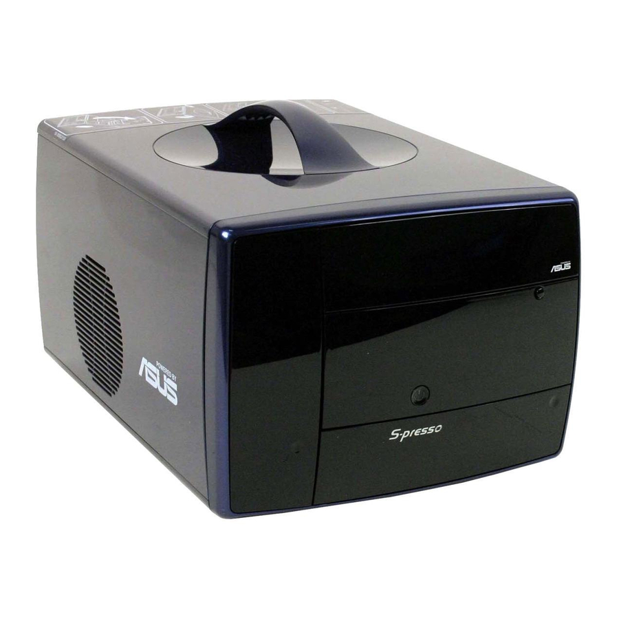
Thank you for choosing the ASUS S-presso Multimedia System! Now you can experience the quality entertainment of consumer electronics right on your own desktop. The ASUS S-presso is a smart personal computer and a versatile home entertainment system in one. Powered by the ASUS P4P8T motherboard, S-presso delivers robust technology for your computing and multimedia entertainment needs. -
Page 13: Optical Drive
The touch sensors are sensitive. Slightly touch the function you want to enable. Do not press the front panel too hard to prevent damage to the panel and the sensors. 1 . 1 . C a r d s l o t s d o o r C a r d s l o t s d o o r C a r d s l o t s d o o r C a r d s l o t s d o o r. - Page 14 9 . 9 . S T O P s e n s o r . Touch this sensor to stop the audio track/file being S T O P s e n s o r . S T O P s e n s o r . S T O P s e n s o r .
-
Page 15: Front Panel (Internal)
Front panel (internal) The storage card slots and several I/O ports are located inside the internal front panel doors. Press the access buttons to open the internal front panel doors. 1 7 . 1 7 . S e c u r e D i g i t a l ™ / M u l t i m e d i a C a r d s l o t . 1 7 . -
Page 16: Rear Panel
Rear panel The S-presso rear panel includes the power socket and several I/O ports that allow convenient connection of devices. 1 . 1 . P o w e r s u p p l y u n i t f a n . This fan provides ventilation inside the P o w e r s u p p l y u n i t f a n . - Page 17 1 3 . 1 3 . 1 3 . L i n e I n p o r t ( l i g h t b l u e ) . L i n e I n p o r t ( l i g h t b l u e ) . L i n e I n p o r t ( l i g h t b l u e ) .
-
Page 18: Internal Components
Internal components The illustration below is the internal view of the system when you remove the top cover. The installed components are labeled for your reference. Proceed to Chapter 2 for instructions on installing other system components. Optical drive bay HDD drive bay Storage card slot I/O slot... -
Page 19: Led Panel
LED panel The S-presso LED panel on the S-presso S1-P111 model displays different system information depending on the system mode. Below are the LED panel icons representing the different modes: • The I n s t a n t O n I n s t a n t O n I n s t a n t O n I n s t a n t O n... - Page 20 8 . 8 . S t a t u s d i s p l a y . When the system is powered off, in soft-off or S t a t u s d i s p l a y . S t a t u s d i s p l a y .
- Page 21 Chapter 2 This chapter provides step-by-step instructions on how to install components in the system. A S U S S - p r e s s o b a r e b o n e s y s t e m A S U S S - p r e s s o b a r e b o n e s y s t e m A S U S S - p r e s s o b a r e b o n e s y s t e m A S U S S - p r e s s o b a r e b o n e s y s t e m...
-
Page 22: Chapter 2: Basic Installation
Preparation Before you proceed, make sure that you have all the components that you plan to install in the system. Basic components to install Basic components to install Basic components to install Basic components to install Basic components to install Central processing unit (CPU) DDR Dual Inline Memory Module (DIMM) Expansion card(s) -
Page 23: Removing The Front Panel
Removing the front panel To remove the front panel: Locate the groove under the front panel. Position your four fingers under the groove, with your thumb supporting the lower portion of the front panel. Slightly pull towards you until the lower portion disengages from the chassis. -
Page 24: Removing The Cover
Removing the cover To remove the cover: On the rear panel, locate the thumbscrew that secures the cover to the chassis. Turn the thumbscrew counterclockwise unti it gets loose. The thumbscrew cannot be removed from the chassis. Firmy grip the top handle and push the cover about 1 cm forward. -
Page 25: Removing The Power Supply Unit
Removing the power supply unit You must remove the power supply unit (PSU) before you can install a central processing unit (CPU) and other system components. To remove the PSU: Disconnect the power plugs on the motherboard. Locate the lever that secures the PSU. -
Page 26: Installing A Cpu
Installing a CPU The motherboard comes with a surface mount 478-pin Zero Insertion Force (ZIF) socket. This socket is designed for an Intel with up to 3.4 GHz core frequency and 800 MHz FSB. 2.6.1 2.6.1 2.6.1 Removing the CPU fan and heatsink assembly Removing the CPU fan and heatsink assembly Removing the CPU fan and heatsink assembly 2.6.1... -
Page 27: Cpu Installation
2.6.2 2.6.2 CPU installation CPU installation 2.6.2 2.6.2 2.6.2 CPU installation CPU installation CPU installation To install the CPU: Locate the 478-pin CPU socket on the motherboard. Unlock the socket by pressing the lever sideways. Lift the lever up to a 90° angle. Position the CPU above the socket such that its marked corner (gold mark) matches the base of the socket lever. -
Page 28: Re-Installing The Cpu Fan And Heatsink Assembly
2.6.3 2.6.3 2.6.3 Re-installing the CPU fan and heatsink Re-installing the CPU fan and heatsink Re-installing the CPU fan and heatsink 2.6.3 2.6.3 Re-installing the CPU fan and heatsink Re-installing the CPU fan and heatsink assembly assembly assembly assembly assembly To re-install the CPU fan and heatsink assembly: Position the CPU fan and heatsink assembly on top of the installed CPU. -
Page 29: Installing A Dimm
You may install up to 2 GB system memory using 64 MB, 128 MB, 256 MB, 512 MB, and 1 GB DDR DIMMs. Obtain DDR DIMMs only from ASUS qualified vendors. Refer to the Qualified DDR400 vendors list below. Visit the ASUS website (www.asus.com) for the latest DDR Qualified Vendors List. -
Page 30: Dimm Installation
Memory frequency/CPU FSB synchronization Memory frequency/CPU FSB synchronization Memory frequency/CPU FSB synchronization Memory frequency/CPU FSB synchronization Memory frequency/CPU FSB synchronization The system motherboard supports different memory frequencies depending on the CPU FSB (Front Side Bus) and the type of DDR DIMM. C P U F S B C P U F S B C P U F S B... -
Page 31: Installing An Expansion Card
Installing an expansion card In the future, you might need to install expansion cards. The motherboard has one PCI and one Accelerated Graphics Port (AGP) slot. The following sub-sections describe the slots and the expansion cards that they support. 2.8.1 2.8.1 2.8.1 Expansion slots... -
Page 32: Expansion Card Installation
2.8.2 2.8.2 2.8.2 Expansion card installation Expansion card installation Expansion card installation 2.8.2 2.8.2 Expansion card installation Expansion card installation To install an expansion card: Before installing the expansion card, read the documentation that came with it and make the necessary hardware settings for the card. Locate the hinge lock that secures the expansion card slot. -
Page 33: Configuring An Expansion Card
2.8.3 2.8.3 2.8.3 Configuring an expansion card Configuring an expansion card Configuring an expansion card 2.8.3 2.8.3 Configuring an expansion card Configuring an expansion card After installing the expansion card, configure it by adjusting the software settings. Turn on the system and change the necessary BIOS settings, if any. See Chapter 3 for information on the BIOS setup. -
Page 34: Installing An Optical Drive
Installing an optical drive The S-presso system comes with one optical drive bay. Refer to this section to install an optical drive. Set your optical drive as Slave device before connecting the IDE cable and power plug. Refer to the optical drive documentation on how to set the drive as a Slave device. - Page 35 Connect a power cable from the power supply unit to the power connector at the back of the optical drive. Connect one end of the IDE ribbon cable to the IDE interface at the back of the optical drive, matching the red stripe on the cable with Pin 1 on the IDE interface.
-
Page 36: 2.10 Installing A Hard Disk Drive
2.10 Installing a hard disk drive The system supports one Ultra ATA/133 IDE hard disk drive (HDD). To install a hard disk drive: Drive two screws in each side of the hard disk drive as shown. Remove the cover. Refer to section “2.4 Removing the cover”... -
Page 37: 2.11 Re-Installing The Power Supply Unit
2.11 Re-installing the power supply unit Re-install the power supply unit (PSU) after installing the system components and reconnecting the cables. To reinstall the PSU: Replace the metal tray. Make sure that the hooks align to their respective grooves. Slide the PSU toward the direction of the rear panel until it fits in place. -
Page 38: Voltage Selector
Connect the 4-pin power plug to the power connector of the optical disk drive. Connect the 4-pin power plug to the power connector of the VGA card. Connect the 4-pin power plug to the power connector of the hard disk drive. -
Page 39: Power Supply Specifications
2.11.2 Power supply specifications 2.11.2 2.11.2 Power supply specifications Power supply specifications Power supply specifications 2.11.2 2.11.2 Power supply specifications Input characteristics Input characteristics Input characteristics Input characteristics Input characteristics I n p u t V o l t a g e R a n g e I n p u t V o l t a g e R a n g e I n p u t V o l t a g e R a n g e I n p u t V o l t a g e R a n g e... -
Page 40: 2.11 Replacing The Cover
Output ripple Output ripple Output ripple Output ripple Output ripple P a r a m e t e r P a r a m e t e r P a r a m e t e r P a r a m e t e r P a r a m e t e r R i p p l e &... -
Page 41: 2.12 Connecting External Devices
Tighten the screw by turning it clockwise to secure the cover to the rear panel. 2.12 Connecting external devices To the front panel To the front panel To the front panel To the front panel To the front panel M i c M i c H e a d p h o n e H e a d p h o n e... - Page 42 To the rear panel To the rear panel To the rear panel To the rear panel To the rear panel P S / 2 m o u s e P S / 2 m o u s e P S / 2 m o u s e P S / 2 m o u s e P S / 2 m o u s e P S / 2 K B...
- Page 43 Chapter 3 This chapter gives information about the motherboard that comes with the system. This chapter includes the motherboard layout, jumper settings, and connector locations. A S U S S - p r e s s o b a r e b o n e s y s t e m A S U S S - p r e s s o b a r e b o n e s y s t e m A S U S S - p r e s s o b a r e b o n e s y s t e m A S U S S - p r e s s o b a r e b o n e s y s t e m...
-
Page 44: Chapter 3: Motherboard Info
Introduction The ASUS P4P8T motherboard comes already installed in the ASUS S-presso barebone system. This chapter provides technical information about the motherboard for future upgrades or system reconfiguration. Motherboard layout PS/2 T:Mouse B:Keyboard VGA1 Line Line USB2.0 T: USB1 ATX12V B: USB2 USB2.0... -
Page 45: Jumper
Jumper Clear RTC RAM (CLRTC) Clear RTC RAM (CLRTC) Clear RTC RAM (CLRTC) Clear RTC RAM (CLRTC) Clear RTC RAM (CLRTC) This jumper allows you to clear the Real Time Clock (RTC) RAM in CMOS. You can clear the CMOS memory of date, time, and system setup parameters by erasing the CMOS RTC RAM data. -
Page 46: Connectors
Connectors This section describes and illustrates the connectors on the motherboard. See page 1-6 for the description of rear panel connectors. 1 . 1 . U S B c o n n e c t o r s ( 1 0 - 1 p i n U S B 5 6 , 1 0 - 1 p i n U S B 7 8 ) U S B c o n n e c t o r s ( 1 0 - 1 p i n U S B 5 6 , 1 0 - 1 p i n U S B 7 8 ) U S B c o n n e c t o r s ( 1 0 - 1 p i n U S B 5 6 , 1 0 - 1 p i n U S B 7 8 ) U S B c o n n e c t o r s ( 1 0 - 1 p i n U S B 5 6 , 1 0 - 1 p i n U S B 7 8 ) - Page 47 2 . 2 . D i g i t a l a u d i o c o n n e c t o r ( 4 - 1 p i n S P D I F O U T ) D i g i t a l a u d i o c o n n e c t o r ( 4 - 1 p i n S P D I F O U T ) D i g i t a l a u d i o c o n n e c t o r ( 4 - 1 p i n S P D I F O U T ) D i g i t a l a u d i o c o n n e c t o r ( 4 - 1 p i n S P D I F O U T )
- Page 48 4 . 4 . C P U a n d c h a s s i s f a n c o n n e c t o r s ( 3 - p i n C P U _ F A N , C P U a n d c h a s s i s f a n c o n n e c t o r s ( 3 - p i n C P U _ F A N , C P U a n d c h a s s i s f a n c o n n e c t o r s ( 3 - p i n C P U _ F A N , C P U a n d c h a s s i s f a n c o n n e c t o r s ( 3 - p i n C P U _ F A N ,...
- Page 49 5 . 5 . A T X p o w e r c o n n e c t o r s ( 2 0 - p i n A T X P W R , 4 - p i n A T X 1 2 V ) A T X p o w e r c o n n e c t o r s ( 2 0 - p i n A T X P W R , 4 - p i n A T X 1 2 V ) A T X p o w e r c o n n e c t o r s ( 2 0 - p i n A T X P W R , 4 - p i n A T X 1 2 V ) A T X p o w e r c o n n e c t o r s ( 2 0 - p i n A T X P W R , 4 - p i n A T X 1 2 V )
- Page 50 6 . 6 . I D E c o n n e c t o r s ( 4 0 - 1 p i n P R I _ I D E , S E C _ I D E ) I D E c o n n e c t o r s ( 4 0 - 1 p i n P R I _ I D E , S E C _ I D E ) I D E c o n n e c t o r s ( 4 0 - 1 p i n P R I _ I D E , S E C _ I D E ) I D E c o n n e c t o r s ( 4 0 - 1 p i n P R I _ I D E , S E C _ I D E )
-
Page 51: Hard Disk Drives
8 . 8 . S e r i a l A T A c o n n e c t o r s ( 7 - p i n S A T A 2 , S A T A 1 ) S e r i a l A T A c o n n e c t o r s ( 7 - p i n S A T A 2 , S A T A 1 ) S e r i a l A T A c o n n e c t o r s ( 7 - p i n S A T A 2 , S A T A 1 ) S e r i a l A T A c o n n e c t o r s ( 7 - p i n S A T A 2 , S A T A 1 ) - Page 52 Required IDE Configuration settings in BIOS Refer to the following table for the appropriate BIOS settings of the above P-ATA and S-ATA device configurations. See section “5.3. 5 IDE Configuration” for details on the related BIOS items. B I O S i t e m B I O S i t e m B I O S i t e m B I O S i t e m...
- Page 53 1 1 . 1 1 . S y s t e m p a n e l c o n n e c t o r ( 8 - 1 p i n P A N E L ) 1 1 . 1 1 .
- Page 54 3 - 1 2 3 - 1 2 3 - 1 2 3 - 1 2 3 - 1 2 C h a p t e r 3 : M o t h e r b o a r d i n f o C h a p t e r 3 : M o t h e r b o a r d i n f o C h a p t e r 3 : M o t h e r b o a r d i n f o C h a p t e r 3 : M o t h e r b o a r d i n f o...
- Page 55 Chapter 4 This chapter tells how to change system settings through the BIOS Setup menus and describes the BIOS parameters. A S U S S - p r e s s o b a r e b o n e s y s t e m A S U S S - p r e s s o b a r e b o n e s y s t e m A S U S S - p r e s s o b a r e b o n e s y s t e m A S U S S - p r e s s o b a r e b o n e s y s t e m...
-
Page 56: Chapter 4: Bios Information
Use this file only when you do not have a copy of the original motherboard BIOS file in a floppy disk. • Visit the ASUS website and download the latest BIOS file for this motherboard using the ASUS Update utility. 4.1.1 4.1.1... -
Page 57: Using Afudos To Copy The Current Bios
Copy the original (or the latest) motherboard BIOS to the bootable floppy disk. 4.1.2 4.1.2 Using AFUDOS to copy the current BIOS Using AFUDOS to copy the current BIOS 4.1.2 4.1.2 4.1.2 Using AFUDOS to copy the current BIOS Using AFUDOS to copy the current BIOS Using AFUDOS to copy the current BIOS The AFUDOS.EXE utility can also be used to copy the current system BIOS settings to a floppy or hard disk. -
Page 58: Using Afudos To Update The Bios
BIOS file to a floppy diskette. To update the BIOS using the AFUDOS.EXE: Visit the ASUS website (www.asus.com) to download the latest BIOS file for your motherboard. Save the BIOS file to a bootable floppy disk. Write down the BIOS file name to a piece of paper. You need to type the... - Page 59 When the BIOS update process is complete, the utility returns to the DOS prompt. A:\>afudos /ip4p8t.rom AMI Firmware Update Utility - Version 1.10 Copyright (C) 2002 American Megatrends, Inc. All rights reserved. Reading file ... done Erasing flash ... done Writing flash ...
-
Page 60: Using Asus Ez Flash To Update The Bios
Using ASUS EZ Flash to update the BIOS Using ASUS EZ Flash to update the BIOS The ASUS EZ Flash feature allows you to easily update the BIOS without having to go through the long process of booting from a floppy disk and using a DOS-based utility. -
Page 61: Recovering The Bios With Crashfree Bios 2
Insert a floppy disk that contains the original, or the latest, BIOS file for this motherboard (P 4 P 8 T . R O M downloaded from the ASUS website has a different filename (e.g. P 4 P 8 T 1 1 . R O M P 4 P 8 T 1 1 . - Page 62 When the BIOS update process is complete, reboot the system. The recovered BIOS may not be the latest BIOS version for this motherboard. Visit the ASUS website (www.asus.com) to download the latest BIOS file. 4 - 8...
-
Page 63: Asus Update
P r o g r a m s > A S U S > A S U S U p d a t e > A S U S U p d a t e P r o g r a m s > A S U S > A S U S U p d a t e > A S U S U p d a t e. The ASUS P r o g r a m s >... - Page 64 If you selected updating/ downloading from the Internet, select the ASUS FTP site nearest you to avoid network traffic, or choose A u t o S e l e c t S e l e c t N e x t...
-
Page 65: Bios Setup Program
BIOS Setup program This motherboard supports a programmable Firmware Hub (FWH) that you can update using the provided utility described in section “ 4.1 Managing and updating your BIOS.” Use the BIOS Setup program when you are installing a motherboard, reconfiguring your system, or prompted to “Run Setup.”... -
Page 66: Bios Menu Screen
C o n f i g u r a t i o n f i e l d s [11:10:19] [Tue, 06/29/2004] [English] [Maxtor 6Y080L0] [ASUS CDS520/] [Not Detected] [Not Detected] [Not Detected] [Not Detected] C h a p t e r 4 : B I O S i n f o r m a t i o n... -
Page 67: Menu Items
[Tue, 06/29/2004] select a field. Language [English] Primary IDE Master [Maxtor 6Y080L0] Use [+] or [-] to Primary IDE Slave [ASUS CDS520/] configure system Secondary IDE Master [Not Detected] time. Secondary IDE Slave [Not Detected] Third IDE Master [Not Detected]... -
Page 68: Main Menu
[Tue, 06/29/2004] [SHIFT-TAB] to select a [English] field. [Maxtor 6Y080L0] Use [+] or [-] to [ASUS CDS520/] configure system time. [Not Detected] [Not Detected] [Not Detected] [Not Detected] C h a p t e r 4 : B I O S i n f o r m a t i o n... -
Page 69: Primary And Secondary Ide Master/Slave; Third And Fourth Ide Master
4.3.3 4.3.3 Primary and Secondary IDE Master/Slave; Primary and Secondary IDE Master/Slave; 4.3.3 4.3.3 4.3.3 Primary and Secondary IDE Master/Slave; Primary and Secondary IDE Master/Slave; Primary and Secondary IDE Master/Slave; Third and Fourth IDE Master Third and Fourth IDE Master Third and Fourth IDE Master Third and Fourth IDE Master Third and Fourth IDE Master... -
Page 70: Ide Configuration
PIO Mode [Auto] PIO Mode [Auto] PIO Mode [Auto] PIO Mode [Auto] PIO Mode [Auto] Selects the PIO mode. Configuration options: [Auto] [0] [1] [2] [3] [4] DMA Mode [Auto] DMA Mode [Auto] DMA Mode [Auto] DMA Mode [Auto] DMA Mode [Auto] Selects the DMA mode. -
Page 71: System Information
Enhanced Mode Support On [S-ATA] The default setting S-ATA allows you to use native OS on Serial ATA and Parallel ATA ports. We recommend that you do not change the default setting for better OS compatibility. In this setting, you may use legacy OS on the Parallel ATA ports o n l y i f Serial ATA device. -
Page 72: Advanced Menu
Advanced menu The Advanced menu items allow you to change the settings for the CPU and other system devices. Take caution when changing the settings of the Advanced menu items. Incorrect field values may cause the system to malfunction. CPU Configuration Chipset Onboard Devices Configuration PCI PnP... -
Page 73: Chipset
4.4.2 4.4.2 Chipset Chipset 4.4.2 4.4.2 4.4.2 Chipset Chipset Chipset The Chipset menu items allow you to change the advanced chipset settings. Select an item then press <Enter> to display the sub-menu. Advanced Chipset settings WARNING: Setting wrong values in the sections below may cause system to malfunction. - Page 74 DRAM RAS# to CAS# Delay [4 Clocks] This item controls the latency between the DDR SDRAM active command and the read/write command. Configuration options: [4 Clocks] [3 Clocks] [2 Clocks] DRAM Precharge Delay [8 Clocks] Configuration options: [8 Clocks] [7 Clocks] [6 Clocks] [5 Clocks] DRAM Burst Length [8 Clocks] Configuration options: [4 Clocks] [8 Clocks] Internal Graphic Accelerate Mode [Auto]...
-
Page 75: Onboard Devices Configuration
TV Standard [Auto] TV Standard [Auto] TV Standard [Auto] TV Standard [Auto] TV Standard [Auto] Allows you to select the TV standard when you selected TV as your boot display device. Configuration options: [Auto] [NTSC_M] [NTSC_M_J] [NTSC_433] [NTSC_N] [PAL_B] [PAL_G] [PAL_D] [PAL_H] [PAL_I] [PAL_M] [PAL_N] [PAL_60] [SECAM_L] [SECAM_L1] [SECAM_B] MPS Revision [1.4] MPS Revision [1.4]... - Page 76 Parallel Port Address [378] Parallel Port Address [378] Parallel Port Address [378] Parallel Port Address [378] Parallel Port Address [378] Allows you to select the Parallel Port base addresses. Configuration options: [Disabled] [378] [278] Parallel Port Mode [EPP+ECP] Parallel Port Mode [EPP+ECP] Parallel Port Mode [EPP+ECP] Parallel Port Mode [EPP+ECP] Parallel Port Mode [EPP+ECP]...
-
Page 77: Pci Pnp
4.4.4 4.4.4 PCI PnP PCI PnP 4.4.4 4.4.4 4.4.4 PCI PnP PCI PnP PCI PnP The PCI PnP menu items allow you to change the advanced settings for PCI/PnP devices. The menu includes setting IRQ and DMA channel resources for either PCI/PnP or legacy ISA devices, and setting the memory size block for legacy ISA devices. -
Page 78: Usb Configuration
PCI IDE BusMaster [Enabled] PCI IDE BusMaster [Enabled] PCI IDE BusMaster [Enabled] PCI IDE BusMaster [Enabled] PCI IDE BusMaster [Enabled] Allows the BIOS to use PCI bus mastering when reading/writing to IDE devices. Configuration options: [Disabled] [Enabled] IRQxx [Available] IRQxx [Available] IRQxx [Available] IRQxx [Available] IRQxx [Available]... -
Page 79: Load Miniloader
USB 2.0 Controller [Enabled] USB 2.0 Controller [Enabled] USB 2.0 Controller [Enabled] USB 2.0 Controller [Enabled] USB 2.0 Controller [Enabled] Allows you to enable or disable the USB 2.0 controller. Configuration options: [Enabled] [Disabled] USB 2.0 Controller Mode [FullSpeed] USB 2.0 Controller Mode [FullSpeed] USB 2.0 Controller Mode [FullSpeed] USB 2.0 Controller Mode [FullSpeed] USB 2.0 Controller Mode [FullSpeed]... -
Page 80: Power Menu
Power menu The Power menu items allow you to change the settings for the Advanced Power Management (APM). Select an item then press <Enter> to display the configuration options. Suspend Mode Repost Video on S3 Resume ACPI 2.0 Support ACPI ASIC Support APM Configuration Hardware Monitor 4.5.1... -
Page 81: Apm Configuration
4.5.5 4.5.5 APM Configuration APM Configuration 4.5.5 4.5.5 4.5.5 APM Configuration APM Configuration APM Configuration APM Configuration Restore on AC Power Loss Power On By PS/2 Devices Power On By External Modems Power On By PCI Devices Power On By RTC Alarm Restore on AC Power Loss [Power Off] Restore on AC Power Loss [Power Off] Restore on AC Power Loss [Power Off]... -
Page 82: Hardware Monitor
SMART Q-Fan Function [Enabled] SMART Q-Fan Function [Enabled] SMART Q-Fan Function [Enabled] Allows you to enable or disable the ASUS Smart Q-Fan feature that smartly adjusts the fan speeds for more efficient system operation. Configuration options: [Enabled] [Disabled] 4 - 2 8... -
Page 83: Boot Menu
Boot menu The Boot menu items allow you to change the system boot options. Select an item then press <Enter> to display the sub-menu. Boot Settings Boot Device Priority Removable Drives Boot Settings Configuration Security 4.6.1 4.6.1 4.6.1 Boot Device Priority Boot Device Priority Boot Device Priority 4.6.1... -
Page 84: Removable Drives
This allows you to enable or disable the full screen logo display feature. Configuration options: [Disabled] [Enabled] Make sure that the Full Screen Logo item is set to [Enabled] if you want to use the ASUS MyLogo2™ feature. 4 - 3 0 4 - 3 0... - Page 85 Add On ROM Display Mode [Force BIOS] Add On ROM Display Mode [Force BIOS] Add On ROM Display Mode [Force BIOS] Add On ROM Display Mode [Force BIOS] Add On ROM Display Mode [Force BIOS] Sets the display mode for option ROM. Configuration options: [Force BIOS] [Keep Current] Bootup Num-Lock [On] Bootup Num-Lock [On]...
-
Page 86: Security
4.6.4 4.6.4 4.6.4 Security Security Security 4.6.4 4.6.4 Security Security The Security menu items allow you to change the system security settings. Select an item then press <Enter> to display the configuration options. Security Settings Supervisor Password User Password Change Supervisor Password Boot Sector Virus Protection Change Supervisor Password Change Supervisor Password... - Page 87 After you have set a supervisor password, the other items appear to allow you to change other security settings. Security Settings Supervisor Password User Password Change Supervisor Password User Access Level Change User Password Clear User Password Password Check Boot Sector Virus Protection User Access Level (Full Access] User Access Level (Full Access] User Access Level (Full Access]...
-
Page 88: Exit Menu
Clear User Password Clear User Password Clear User Password Clear User Password Clear User Password Select this item if you want to clear the user password. Password Check [Setup] Password Check [Setup] Password Check [Setup] Password Check [Setup] Password Check [Setup] When set to [Setup], BIOS checks for user password when accessing the Setup utility. - Page 89 If you attempt to exit the Setup program without saving your changes, the program prompts you with a message asking if you want to save your changes before exiting. Pressing <Enter> saves the changes while exiting. Exit & Discard Changes Exit &...
- Page 90 4 - 3 6 4 - 3 6 4 - 3 6 4 - 3 6 4 - 3 6 C h a p t e r 4 : B I O S i n f o r m a t i o n C h a p t e r 4 : B I O S i n f o r m a t i o n C h a p t e r 4 : B I O S i n f o r m a t i o n C h a p t e r 4 : B I O S i n f o r m a t i o n...
- Page 91 Chapter 5 This chapter helps you power up the system and install drivers and utilities from the support CD. ASUS S-presso barebone system...
-
Page 92: Chapter 5: Starting Up
For model S1-P111 with Instant On feature, make sure you have installed Instant On b e f o r e S o f t w S o f t w S o f t wa r e I n f o r m a t i o n a r e I n f o r m a t i o n guide for instructions on installing Instant On. -
Page 93: Support Cd Information
Screen display and driver options may not be the same for other operating system versions. • The contents of the support CD are subject to change at any time without notice. Visit the ASUS website for updates. 5.3.1 5.3.1 5.3.1... -
Page 94: Drivers Menu
USB 2.0 Driver USB 2.0 Driver Installs the USB 2.0 driver. ASUS UB6220 7 in 1 Card Reader Driver ASUS UB6220 7 in 1 Card Reader Driver ASUS UB6220 7 in 1 Card Reader Driver ASUS UB6220 7 in 1 Card Reader Driver ASUS UB6220 7 in 1 Card Reader Driver Installs the ASUS UB6220 7-in-1 Card Reader driver. -
Page 95: Utilities Menu
ASUS Update ASUS Update ASUS Update ASUS Update Installs the ASUS Update that allows you to update the motherboard BIOS in Windows ® environment, This utility requires an Internet connection either through a network or an Internet Service Provider (ISP). See page 5-8for details. -
Page 96: Asus Contact Information
5.3.4 5.3.4 ASUS contact information ASUS contact information ASUS contact information 5.3.4 5.3.4 ASUS contact information ASUS contact information Click the Contact tab to display the ASUS contact information. 5.3.5 5.3.5 5.3.5 Other information Other information Other information 5.3.5 5.3.5... - Page 97 Displays the support CD contents in graphical format. Technical support form Technical support form Technical support form Technical support form Technical support form Displays the ASUS Technical Support Request Form that you have to fill out when requesting technical support. Filelist Filelist Filelist Filelist...
-
Page 98: Software Information
ASUS Update ASUS Update ASUS Update The ASUS Update is a utility that allows you to update the motherboard BIOS and drivers. This utility requires an Internet connection either through a network or an Internet Service Provider (ISP). Follow these steps to use the ASUS Update. - Page 99 From the FTP site, select the BIOS version that you wish to N e x t N e x t download. Click N e x t N e x t. N e x t The BIOS ROM information is displayed. Click Flash to update the BIOS.
-
Page 100: Asus Pc Probe
ASUS PC Probe ASUS PC Probe ASUS PC Probe is a monitoring utility that continuously keeps track of vital system information such as fan rotations, voltages, and temperatures. This utility also allows you to check other information about your computer, including hard disk space, memory usage, and CPU type, CPU speed, and internal/external frequencies through the DMI Explorer. -
Page 101: Monitoring Tab
Using ASUS PC Probe Using ASUS PC Probe Using ASUS PC Probe Using ASUS PC Probe Using ASUS PC Probe Monitoring tab M o n i t o r S u m m a r y M o n i t o r S u m m a r y... -
Page 102: Information Tab
S e t t i n g s S e t t i n g s S e t t i n g s S e t t i n g s S e t t i n g s Lets you set threshold levels and polling intervals or refresh times of the system temperature, fan... - Page 103 A S U S P C P r o b e T a s k B a r I c o n Right clicking the PC Probe icon brings up a menu to open or exit ASUS PC Probe and pause or resume all system monitoring.
-
Page 104: Multi-Channel Audio Feature
5.4.3 5.4.3 Multi-channel audio feature Multi-channel audio feature 5.4.3 5.4.3 5.4.3 Multi-channel audio feature Multi-channel audio feature Multi-channel audio feature The ADI AD1888 audio CODEC provides 6-channel audio capability. Install the S o u n d M A X S o u n d M A X S o u n d M A X S o u n d M A X ®... - Page 105 After selecting an option, test your setting by clicking the P l a y T e s t N o i s e button. While testing, you N o i s e N o i s e N o i s e N o i s e will see a black circle moving on the screen indicating the audio...
- Page 106 Adjusting the volume settings Adjusting the volume settings Adjusting the volume settings Adjusting the volume settings Adjusting the volume settings After rebooting the system, click on the volume control icon on the Windows ® taskbar to display the V o l u m e C o n t r o l V o l u m e C o n t r o l window.