
Related Manuals for Metrologic MS7320 InVista Series


Summary of Contents for Metrologic MS7320 InVista Series
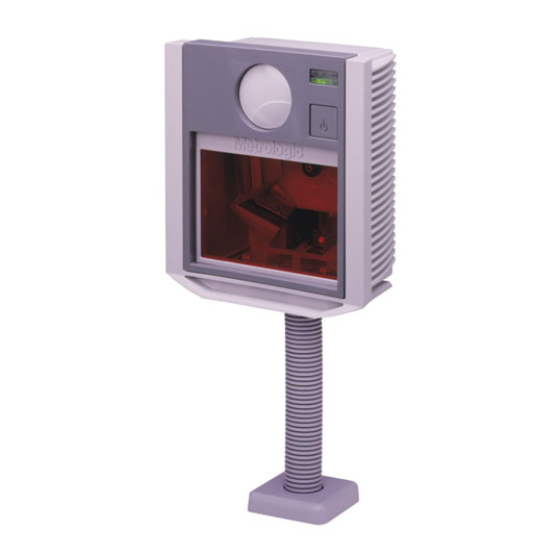
- Page 1 METROLOGIC INSTRUMENTS, INC. ® MS7320 InVista Series Installation and User’s Guide...
- Page 2 Copyright © 2004 by Metrologic Instruments, Inc. All rights reserved. No part of this work may be reproduced, transmitted, or stored in any form or by any means without prior written consent, except by reviewer, who may quote brief passages in a review, or provided for in the Copyright Act of 1976.
-
Page 3: Table Of Contents
For Stand-Alone Keyboard Interface... 6 For USB Interface... 7 For RS232 or Light Pen Interfaces... 8 For IBM 46xx Interface ... 10 Of a Secondary Scanner ... 11 Scanner Parts ... 14 Maintenance... 14 Cable Cover Installation and Removal... 15 Face Plate Removal... - Page 4 ABLE OF ONTENTS Scanner and Cable Terminations Scanner Pinout Connections... 44 Cable Connector Configurations (Host End) ... 46 Limited Warranty ... 48 Laser and Product Safety... 49 Patents ... 51 Index ... 52...
-
Page 5: Introduction
This fixed mount laser bar code scanner provides ease of use and high throughput speeds by featuring a large, dynamic, and aggressive scan volume. The MS7320 is equipped with a multitude of standard features including: • Automatic Scanning Operation •... -
Page 6: Scanner And Accessories
CCESSORIES Part # MS7320 InVista Series Scanner 00-02407 MetroSelect 00-02896 MS7320 InVista Series Installation and User’s Guide 52-52511 24” EAS Cable Guides also available for download at www.metrologic.com. Part # Straight PowerLink Cable with built in power jack. 54-54xxx* 2.1 m (7') cord with short strain relief xxx* specifies connection to the host. - Page 7 CANNER AND CCESSORIES Part # AC to DC Power Transformer - Regulated 5.2V@ 1A output 46-46759 120V United States 46-46616 220V – 240V Continental European 46-46615 220V – 240V United Kingdom 46-46984 220V – 240V China 46-46985 220V – 240V Australia 46-00174 3"...
-
Page 8: Installation For Ocia Interface
MetroSelect Configuration Guide ( Caution: To maintain compliance with applicable standards, all circuits connected to the scanner must meet the requirements for SELV (Safety Extra Low Voltage) according to EN 60950. To maintain compliance with standard CSA C22.2 No. 60950-00/UL 60950 and norm EN 60950, the power source should meet applicable performance requirements for a limited power source. -
Page 9: For Keyboard Wedge Interface
10. Snap on the cable cover. Caution: To maintain compliance with applicable standards, all circuits connected to the scanner must meet the requirements for SELV (Safety Extra Low Voltage) according to EN 60950. To maintain compliance with standard CSA C22.2 No. 60950-00/UL 60950 and norm EN 60950, the power source should meet applicable performance requirements for a limited power source. -
Page 10: For Stand-Alone Keyboard Interface
10. Snap on the cable cover. Caution: To maintain compliance with applicable standards, all circuits connected to the scanner must meet the requirements for SELV (Safety Extra Low Voltage) according to EN 60950. To maintain compliance with standard CSA C22.2 No. 60950-00/UL 60950 and norm EN 60950, the power source should meet applicable performance requirements for a limited power source. -
Page 11: For Usb Interface
Snap on the cable cover. Caution: To maintain compliance with applicable standards, all circuits connected to the scanner must meet the requirements for SELV (Safety Extra Low Voltage) according to EN 60950. To maintain compliance with standard CSA C22.2 No. 60950-00/UL 60950 and norm EN 60950, the power source should meet applicable performance requirements for a limited power source. -
Page 12: For Rs232 Or Light Pen Interfaces
Snap on the cable cover. Caution: To maintain compliance with applicable standards, all circuits connected to the scanner must meet the requirements for SELV (Safety Extra Low Voltage) according to EN 60950. To maintain compliance with standard CSA C22.2 No. 60950-00/UL 60950 and norm EN 60950, the power source should meet applicable performance requirements for a limited power source. - Page 13 NSTALLATION FOR Codes needed for Step 7 on page 8. For RS232 Communication: Recall Defaults Scan 1 ³ For Light Pen Communication: Recall Defaults Scan 1 ³ RS232 IGHT NTERFACES Enable RS-232 Scan 2 ³ Enable Light Pen/Wand Scan 2 ³...
-
Page 14: For Ibm 46Xx Interface
MLPN Caution: To maintain compliance with applicable standards, all circuits connected to the scanner must meet the requirements for SELV (Safety Extra Low Voltage) according to EN 60950. To maintain compliance with standard CSA C22.2 No. 60950-00/UL 60950 and norm EN 60950, the power source should meet applicable performance requirements for a limited power source. -
Page 15: Of A Secondary Scanner
Connect the other end of the PowerLink RS232 AUX cable into the 1 from the left side of the MS7320. The Aux jack has a square opening. The following Metrologic scanners can be used in the “Aux” input of the MS7320: the MS9520, MS9540, MS6220, MS7120, MS6520, MS6720, MS7220 or another MS7320. - Page 16 NSTALLATION OF A 11. Scan the following bar code to configure the auxiliary port on the MS7320 to accept a Metrologic scanner as the secondary scanner. The following bar codes do not apply when using an MS6720 as a secondary scanner. Contact a Metrologic representative for additional information on the MS6720.
- Page 17 NSTALLATION OF A ECONDARY CANNER Figure 7: Connector Orientation (Top) Auxiliary Scanner Setup (Bottom)
-
Page 18: Scanner Parts
Smudges and dirt can interfere with the proper scanning of a bar code. Therefore, the output window will need occasional cleaning. For the MS7320 glass window: Spray glass cleaner onto lint free, non-abrasive cleaning cloth. Gently wipe the scanner window. -
Page 19: Cable Cover Installation And Removal
ABLE OVER NSTALLATION AND LATE EMOVAL EMOVAL Figure 10: Face Plate Removal Figure 9: Installing the Cable Cover (left). Removing the Cable Cover (bottom right). -
Page 20: Scanner Labels
CANNER ABELS The MS7320 has 2 labels on the back of the unit. These labels contain the model number, date of manufacture, serial number, and caution information. An additional caution label is located under the window faceplate and a label noting the jack interfaces is located under the connector cover. -
Page 21: Indicators
UDIBLE NDICATORS When the MS7320 scanner is in operation, it provides audible feedback. These sounds indicate the status of the scanner. Eight settings are available for the tone of the beep (normal, 6 alternate tones and no tone). To change the tone, use the Multi-Function Button or refer to the MetroSelect Configuration Guide. -
Page 22: Visual
ISUAL NDICATORS There is a red LED and green LED on the front of the MS7320. When the scanner is on, the flashing or constant illumination of the LEDs indicates the status of the current scan and the scanner. No Red or Green LED The LEDs will not be illuminated if the scanner is not receiving power from the host or transformer. -
Page 23: Failure Mode
Three Beeps - on power up If the scanner beeps 3 times on power up then, the nonvolatile memory that holds the scanner configuration has failed. Return the unit for repair at an authorized service center. -
Page 24: Power Save Modes And The Multi-Function Button
OWER ODES AND THE The MS7320 has five configurable power save modes. Refer to the MetroSelect Configuration Guide for additional information on Power Save Modes. Blink Power Save Mode (Default): “Blinks” the laser OFF & ON after a configured period of non-use. - Page 25 The Laser & Motor Off Power Save Mode is the only power save mode that can be activated with the multi-function button. AKING THE NIT FROM The next button depression will awaken the scanner for normal operation. UNCTION UTTON EEPER & M ASER...
-
Page 26: Scan Volume
OLUME 100% UPC B ASED ON ODES Figure 18: Scan Area Top View (top) Side View (Bottom) Specifications are subject to change without notice. -
Page 27: Depth Of Field By Minimum Bar Code Element Width
EPTH OF IELD BY 100% UPC B ASED ON Minimum Bar Code Element Width mils Specifications are subject to change without notice. INIMUM ODES Figure 19: Depth of Field Top View 10.4 LEMENT IDTH... - Page 28 EPTH OF IELD BY 100% UPC B ASED ON Minimum Bar Code Element Width mils Specifications are subject to change without notice. INIMUM ODES Figure 20: Depth of Field Side View 10.4 LEMENT IDTH...
-
Page 29: Flex Stand Installation
TAND NSTALLATION Flex Stand (Optional), Kit Components a. Stand Base Cover... Qty. 1 b. Stand Base ... Qty. 1 c. Small Flex Cover* ... Qty. 1 d. Flex Pole* ... Qty. 1 e. Large Flex Cover*... Qty. 1 f. #8 x 1.00" Wood Screw ... Qty. 4 g. - Page 30 Slide the flex cover(s)* over the flex pole assembly. Figure 23: Pole Assembly Remove the scanner’s cable cover if it was previously installed. Pull the tab on the scanner’s pedestal to release the lock. Slide the pedestal off the scanner. Figure 25: Cable Cover Removal...
- Page 31 Attach the scanner pedestal to the flex pole. Slide the scanner onto the pedestal until it clicks locking the scanner to the stand. Before installing the scanner’s cable cover, refer to pages 4-13 for instructions on the proper cable connections. Install the scanner’s cable cover.
-
Page 32: Eas Deactivation Antenna
SW1 and SW2 are the switch banks inside the Checkpoint Device that set the deactivation range. Metrologic recommends end users program the MS7320 to the Fixed for Low Density Codes - Depth of Field*, so that the unit does not scan out beyond the deactivation range. -
Page 33: Troubleshooting Guide
Make sure the cable is plugged into the scanner. Some host systems cannot supply enough current to power MS7320 series scanner. Use the power supply included with the scanner. Contact a Metrologic Representative, if the unit will not hold the configuration. - Page 34 (Typical of Non-UPC/EAN codes. The scanner defaults to a minimum of 4 character bar code.) If the scanner is setup to support ACK/NAK, RTS/CTS, XON/XOFF or D/E, verify that the host cable and host are supporting the handshaking properly.
- Page 35 Increase the interscan code delay setting. Adjust whether the F0 break is transmitted. It may be necessary to try this in both settings. Enable Caps Lock detect setting of the scanner to detect whether the PC is operating in Caps Lock. SOLUTION...
- Page 36 F0 break is transmitted. It may be necessary to try this in both settings. Enable the caps lock detect setting of the scanner to detect if the PC is operating in Caps Lock. Try operating the scanner in Alt mode.
- Page 37 Refer to the user guide provided with the secondary scanner. 54-54667] Ensure the secondary scanner is MLPN connected to the MS7320 com port marked “Aux” port. * The MS7320 must be The secondary scanner must be configured to send ‘secondary’...
-
Page 38: Design Specifications
Footprint of Stand Weight: Termination: Cable: Specifications are subject to change without notice. MS7320 S ERIES Visible Laser Diode (VLD) @ 650 nm 0.678 mW (peak) 0 mm to 215 mm (0"- 8.5") for 0.33 mm (13 mil) bar code 38 mm (1.5") @ 15 mm (0.6");... - Page 39 NVIRONMENTAL Operating Temperature: Storage Temperature: Humidity: Light Levels: Contaminants: Ventilation: Specifications are subject to change without notice. MS7320 S ERIES 5.2VDC ± 0.25V 1.9 W 360 mA Class II; 5.2 VDC @ 1A IEC 60825-1:1993+A1:1997+A2:2001 EN 60825-1:1994+A11:1996+A2:2001 FCC, ICES-003 & EN 55022 Class B 0°C to 40°C (32°F to 104°F)
-
Page 40: Rs232 Demonstration Program
If the bar code data displays on the screen while using this program, it only demonstrates that the hardware interface and scanner are working. -
Page 41: Applications And Protocols
CANNER DENTIFIER 7320 The MS7320 with Built-in PC Keyboard Wedge Interface is designed to be used for keyboard emulation only. Many RS232 configurable functions available in other Metrologic scanners are also available as keyboard wedge functions. The following are the most important selectable options specific to the keyboard wedge. -
Page 42: Default Settings
The scanner is shipped from the factory configured to a set of default conditions. The default parameter of the scanner has an asterisk ( * ) in the charts on the following pages. If an asterisk is not in the default column then the default setting is Off or Disabled. - Page 43 EFAULT ETTINGS ARAMETER Spaces High as Code 39 Bars High as Scanned Spaces High as Scanned DTS/SIEMENS DTS/NIXDORF NCR F NCR S Poll Light Pen Source Beeper Tone Beep/Transmit Sequence Beeper Volume CommunicationTimeout Razzberry Tone on Timeout Three Beeps on Timeout No Beeps on Timeout Enter Power Save Mode Blink Power Save Mode...
- Page 44 EFAULT ETTINGS ARAMETER Same Symbol Rescan Timeout: 2000 msecs Intercharacter Delay Configurable in 1 msec steps (MAX 255 msecs) Number of Scan Buffers Transmit EAN-8 Check Digit Transmit EAN-13 Check Digit Transmit UPC-A Check Digit Transmit UPC-E Check Digit Expand UPC-E Convert UPC-A to EAN-13 UPC GTIN-14 Format...
- Page 45 EFAULT ETTINGS ARAMETER 8 Data Bits 7 Data Bits Transmit Sanyo ID Characters Nixdorf ID LRC Enabled UPC Prefix UPC Suffix Transmit AIM ID Characters STX Prefix ETX Suffix Carriage Return Line Feed - disabled by default in KBW Tab Prefix Tab Suffix "DE"...
- Page 46 EFAULT ETTINGS ARAMETER Bookland 977 (2 digit) Supplemental Requirement Supplements are not Required Two Digit Redundancy Five Digit Redundancy 100 msec to Find Supplement Configurable in 100 msec steps (MAX 800 msec) Coupon Code 128 Configurable Code Lengths Configurable Prefix Characters Suffix Characters Prefixes for individual Code...
- Page 47 EFAULT ETTINGS Default settings for “Aux” interface The secondary scanner and the MS7320 always communicate via RS232. Data is relayed to the host via various primary interfaces. ARAMETER Aux Baud Rate Aux parity Aux data bits Aux stop bits Aux character RTS...
-
Page 48: Scanner And Cable Terminations Scanner Pinout Connections
CANNER AND ABLE Scanner Pinout Connections The MS7320 scanner interfaces terminate to 10-pin modular jacks located on the back of the unit. The serial # label indicates the model number of the scanner. MS732x-13 OCIA Function Ground RDATA RDATA Return... - Page 49 MS732x-13/-37 Auxiliary Port RS232 IN Only Ground RS232 Receive Input RS232 Transmit Output RTS In CTS Out 6-10 ERMINATIONS Figure 32: Scanner Interface Ports Function MS732x-37 RS232 or Light Pen Function Ground RS232 Transmit Output RS232 Receive Input RTS Output...
-
Page 50: Cable Connector Configurations (Host End)
CANNER AND ABLE Cable Connector Configurations (Host End) PowerLink Cable Shield Ground RS232 Transmit Output RS232 Receive Input DTR Input Power/Signal Ground Reserved CTS Input RTS Output +5VDC xxx* specifies connection to the host USB PowerLink Cable 54-54165, Type A MLPN Ground PowerLink, RS232 AUX Cable... - Page 51 CANNER AND ABLE Cable Connector Configurations (Host End) PowerLink, Keyboard Wedge 54-54002 MLPN Function Keyboard Clock Keyboard Data No Connect Power Ground +5 Volts DC Function Keyboard Data No Connect Power Ground +5 Volts DC PC Clock No Connect Metrologic will supply an adapter cable with a 5-pin DIN male connector on one end and a 6-pin mini DIN female connector on the other.
-
Page 52: Limited Warranty
Series scanners are manufactured by Metrologic at its Blackwood, New Jersey, U.S.A. facility. The MS7320 Series scanners have a three (3) year or two (2) year limited warranty from the date of manufacture. The duration of the warranty is dependent upon the country where the product was purchased. -
Page 53: Laser And Product Safety
ASER AND RODUCT This device complies with Part 15 of the FCC Rules. Operation is subject to the following two conditions: (1) This device may not cause harmful interference, and (2) this device must accept any interference received, including interference that may cause undesired operation. - Page 54 Never attempt to look at the laser beam, even if the scanner appears to be nonfunctional. Never open the scanner in an attempt to look into the device. Doing so could result in hazardous laser light exposure.
-
Page 55: Patents
ATENTS This METROLOGIC product may be covered by one or more of the following U.S. Patents: U.S. Patent No.; 4,960,985; 5,081,342; 5,216,232; 5,557,093; 5,627,359; 5,637,852; 5,661,292; 5,777,315; 5,789,731; 6,029,894; 6,098,885; 6,209,789; 6,347,743; 6,412,696; 6,460,767 No license right or sublicense is granted, either expressly or by implication, estoppel, or otherwise, under any METROLOGIC or third party intellectual property rights (whether or not such third party rights are licensed to METROLOGIC), including any third party patent listed above, except for an... -
Page 56: Index
NDEX Accessories... 2 Adapter... 48 Auxiliary... 2, 34, 44, 46, 47 Scanner ... 11, 12, 13 Beep... 17–19, 29–34, 40 Button... 14, 20, 21 Cable... 8, 14 Adapter ... 48 Area ... 14 Auxiliary ... 2 Communication... 2, 45–48 Cover ... 14, 15 EAS ... - Page 57 NDEX Power Supply ... 3 Protocols ... 38 Radiate... 50 Razzberry Tone... 17, 19, 40 Red... 17, 18, 19, 31 Repair... 49 RS232 ... 9, 33, 37, 39–44, 46, 47 Scan Lines ... 35 Scan Pattern ... 35 Scan Speed... 35 Scan Volume...
- Page 58 Fax: +44 (0) 1256 365955 Email: info@uk.metrologic.com Russia, Moscow Metrologic Russia Tel: +7 095 730 7424 Email: info@ru.metrologic.com Poland, Warsaw Metrologic Instruments Poland Sp.z o.o Tel: +48 (22) 545 04 30 Fax: +48 (22) 545 04 31 Email: info@pl.metrologic.com & A IDDLE FRICAN...
- Page 60 November 2004 Printed in the USA 0 0 - 0 2 8 9 6 E...