
Related Manuals for Metrologic MS7620


Summary of Contents for Metrologic MS7620
- Page 1 METROLOGIC INSTRUMENTS, INC. ™ MS7600 Horizon Series Installation and User’s Guide...
-
Page 3: Table Of Contents
For USB Interface ... 10 For RS232 or Light Pen Interfaces ... 12 For IBM 46xx Interface ... 14 For OCIA Interface... 15 Of a Secondary Scanner ... 16 Scanner Parts... 19 Maintenance... 20 EAS Deactivation Antenna ... 20 Scanner Labels ... 21 Audible Indicators... -
Page 4: Introduction
NTRODUCTION ™ The MS7600 Horizon code scanner. This compact, hands-free scanner is designed with a dense 20-line omnidirectional scan pattern that helps provide fast, efficient throughput with a high first pass read rate. The MS7600 is equipped with a multitude of standard features including: •... -
Page 5: Scanner And Accessories
Other items may be ordered for the specific protocol being used. To order additional items, contact the dealer, distributor or call Metrologic’s Customer Service Department at 1-800-ID-METRO or 1-800-436-3876. ASIC Description ™ Series Scanner ® Programming Guide PTIONAL CCESSORIES Description... - Page 6 Window types (Sapphire, Everscan, and Standard) are not interchangeable due to laser safety and/or scanner performance differences. Caution To change window type, the scanner must be returned to the manufacturer for additional configuration. 46-46602 Stainless Steel Top with Sapphire Window...
-
Page 7: Before Installing Your Ms7600
EFORE NSTALLING When mounting the MS7600 or replacing the Top Plate: Turn the unit upside down. Press on the window. Lift the Top plate straight up to remove. There is no hardware required to remove or replace the top cover. See caution on page 3. -
Page 8: Mounting The Ms7600 Series
MS7600 S OUNTING THE ERIES There are three options for mounting your MS7600. Option “A” uses a shelf to support the unit. Option B lets the unit hang free in the counter top. Option C lets the unit hang free in the counter top with the use of a stainless steel trim ring for support. -
Page 9: Option B: Free Hanging Support
MS7600 S OUNTING THE ERIES B: Free Hanging Support PTION Figure 8: Package Flow (right) Figure 9: Specifications for free hanging support. Figure 10: Installation Tabs... -
Page 10: Option C: Trim Ring
MS7600 S OUNTING THE ERIES C: Trim Ring ( 46-46641, Additional Purchase) PTION MLPN Figure 11: Counter Top Opening for Trim Ring ( 46-46641) MLPN Figure 12: Trim Ring ( 46-46641) Installation MLPN... -
Page 11: Installation For Keyboard Wedge Interface
Turn on the host system. Caution: To maintain compliance with applicable standards, all circuits connected to the scanner must meet the requirements for SELV (Safety Extra Low Voltage) according to EN 60950. To maintain compliance with standard CSA C22.2 No. 60950-00/UL 60950 and norm EN 60950, the power source should meet applicable performance requirements for a limited power source. -
Page 12: For Stand-Alone Keyboard Interface
Turn on the host system. Caution: To maintain compliance with applicable standards, all circuits connected to the scanner must meet the requirements for SELV (Safety Extra Low Voltage) according to EN 60950. To maintain compliance with standard CSA C22.2 No. 60950-00/UL 60950 and norm EN 60950, the power source should meet applicable performance requirements for a limited power source. -
Page 13: For Usb Interface
Continued on next page. Caution: To maintain compliance with applicable standards, all circuits connected to the scanner must meet the requirements for SELV (Safety Extra Low Voltage) according to EN 60950. To maintain compliance with standard CSA C22.2 No. 60950-00/UL 60950 and norm EN 60950, the power source should meet applicable performance requirements for a limited power source. - Page 14 NSTALLATION FOR Manufacturers Note: Plugging the scanner into the USB port of the PC does not guarantee that scanned information will appear at the PC. A software driver and correct configuration setting are also required for proper communication to occur.
-
Page 15: For Rs232 Or Light Pen Interfaces
Turn on the host system. Caution: To maintain compliance with applicable standards, all circuits connected to the scanner must meet the requirements for SELV (Safety Extra Low Voltage) according to EN 60950. To maintain compliance with standard CSA C22.2 No. 60950-00/UL 60950 and norm EN 60950, the power source should meet applicable performance requirements for a limited power source. - Page 16 NSTALLATION FOR Step 7, page 12 continued. For RS232 Communication: Recall Defaults Scan 1 ³ For Light Pen Communication: Recall Defaults Scan 1 ³ RS232 IGHT NTERFACES Enable RS-232 Scan 2 ³ Enable Light Pen/Wand Scan 2 ³...
-
Page 17: For Ibm 46Xx Interface
MLPN Caution: To maintain compliance with applicable standards, all circuits connected to the scanner must meet the requirements for SELV (Safety Extra Low Voltage) according to EN 60950. To maintain compliance with standard CSA C22.2 No. 60950-00/UL 60950 and norm EN 60950, the power source should meet applicable performance requirements for a limited power source. -
Page 18: For Ocia Interface
MetroSelect Programming Guide ( Caution: To maintain compliance with applicable standards, all circuits connected to the scanner must meet the requirements for SELV (Safety Extra Low Voltage) according to EN 60950. To maintain compliance with standard CSA C22.2 No. 60950-00/UL 60950 and norm EN 60950, the power source should meet applicable performance requirements for a limited power source. -
Page 19: Of A Secondary Scanner
Caution: To maintain compliance with applicable standards, all circuits connected to the scanner must meet the requirements for SELV (Safety Extra Low Voltage) according to EN 60950. To maintain compliance with standard CSA C22.2 No. 60950-00/UL 60950 and norm EN 60950, the power source should meet applicable performance requirements for a limited power source. - Page 20 Configuration Guide. The auxiliary input port’s data format must match the main output format of the secondary scanner. 12. Scan the following bar codes, in order, to configure the secondary scanner to match the auxiliary port’s data format. Enable AUX Output ³...
- Page 21 NSTALLATION OF A ECONDARY CANNER Figure 20: Connector Orientation (Top) Secondary Scanner Setup (Bottom)
-
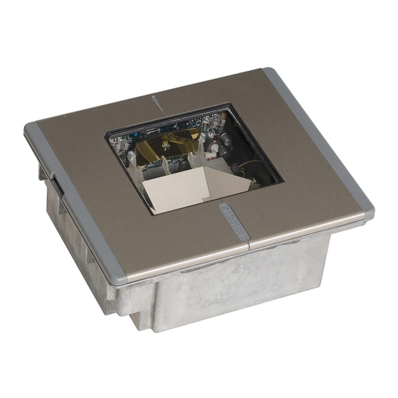
Page 22: Scanner Parts
CANNER ARTS Figure 21: Scanner Parts Output Window (Laser Aperture) Amber LED (Located Under Window) Red LED (Located Under Window) Speaker Cable Connection Area Stainless Steel Top (MS7625 units only) Package Flow Indicator Arrow Head Rubber Connector Plug EAS Deactivation Antenna Connector... -
Page 23: Maintenance
CheckPoint Recommended Unit # Switch Bank Settings MS7620 1, 2, 3, 4, 5, on SW1 & SW2 MS7625 1, 2, 3, 4, 5, on SW1 & SW2 *Note: Minimum element width changes to 6.8 mil when in this mode. -
Page 24: Scanner Labels
CANNER ABELS Each scanner has a label on the bottom of the unit. The label contains information such as the model number, date of manufacture, serial number, and caution information. An additional caution label is located under the top plate. -
Page 25: Audible Indicators
NDICATORS When the MS7600 scanner is in operation, it provides audible feedback. These sounds indicate the status of the scanner. Eight settings are available for the tone of the beep (normal, 6 alternate tones and no tone) plus three volume settings. -
Page 26: Visual Indicators
Figure 24: LEDs No Red or Amber LED The LEDs will not be illuminated if the scanner is not receiving power from the host or transformer. Steady Amber When the laser is active, the amber LED is illuminated. -
Page 27: Failure Modes
Return the unit for repair at an authorized service center. Three Beeps - on power up If the scanner beeps 3 times on power up then, the nonvolatile memory that holds the scanner configuration has failed. Return the unit for repair... -
Page 28: Changing The Beeper Tone & Volume
Next Volume ³ These volume control and beeper tone bar codes can also be found under the Top plate of the scanner and in the MetroSelect Programming Guide. Figure 26: Additional Beeper Tone and Volume Control Bar Codes. & V... -
Page 29: Power Save Modes And Ir Detection
Turns the laser OFF after a programmed period of non-use. The motor continues to spin allowing for a faster “wake” up time. Any movement detected by the IR will “wake” the scanner from the Laser Off power save mode (see figure 27). - Page 30 IR D OWER ODES AND ETECTION Figure 27: IR Activation Area Parallel to Package Flow Specifications are subject to change without notice.
-
Page 31: Scan Volume Specifications
OLUME PECIFICATIONS 100% UPC B ASED ON ODES Figure 28: Scan Volume in Plane Perpendicular to Flow Figure 29: Scan Volume in Plane Parallel to Flow Specifications subject to change without notice. -
Page 32: Depth Of Field By Minimum Bar Code Element Width
EPTH OF IELD BY 100% UPC B ASED ON Figure 30: Depth of Field Perpendicular to Flow Minimum Bar Code Element Width mils Specifications subject to change without notice. INIMUM ODES 10.4 LEMENT IDTH... -
Page 33: Troubleshooting Guide
Make sure the cable is plugged into the scanner. Some host systems cannot supply enough current to power MS7600 series scanner. Use the power supply included with the scanner. Contact a Metrologic Representative, if the unit will not hold the programmed configuration. - Page 34 (Typical of Non-UPC/EAN codes. The scanner defaults to a minimum of 4 character bar code.) If the scanner is setup to support ACK/NAK, RTS/CTS, XON/XOFF or D/E, verify that the host cable and host are supporting the handshaking properly.
- Page 35 Increase the interscan code delay setting. Adjust whether the F0 break is transmitted. It may be necessary to try this in both settings. Enable Caps Lock detect setting of the scanner to detect whether the PC is operating in Caps Lock. SOLUTION...
- Page 36 UIDE ONTINUED Try operating the scanner in Alt mode. Increase the interscan code delay setting. Adjust whether the F0 break is transmitted. It may be necessary to try this in both settings.
- Page 37 The auxiliary input port’s data format must match the main output format of the secondary scanner. Check that the scanner is programmed for USB operation. Check that the host’s USB port is enabled. Unplug & plug USB cable at host end.
-
Page 38: Design Specifications
ESIGN PECIFICATIONS PERATIONAL Light Source: Laser Power: Depth of Field: Width of Scan Field: Scan Speed: Scan Pattern: Scan Lines: Min Bar Width: Decode Capability: System Interfaces: Print Contrast: No. Characters Read: Roll, Pitch, Yaw: Beeper Operation: Indicators (LED): ECHANICAL Dimensions: Weight: Termination:... - Page 39 ESIGN PECIFICATIONS LECTRICAL Input Voltage: Power: Operating Current: Standby Current: DC Transformers: Laser Class: EMC: NVIRONMENTAL Operating Temperature: Storage Temperature: Humidity: Light Levels: Contaminants: Ventilation: Specifications subject to change without notice. ONTINUED MS7600 S ERIES 5.2VDC ± 0.25V 2.6 W 500 mA Laser Off Power Save Mode = <...
-
Page 40: Rs232 Demonstration Program
If the bar code data displays on the screen while using this program, it only demonstrates that the hardware interface and scanner are working. -
Page 41: Applications And Protocols
PPLICATIONS AND The model number on each scanner includes the scanner number and factory default communications protocol. ERSION CANNER DENTIFIER 7620 7625 7620 7625 The MS7600 with Built-in PC Keyboard Wedge Interface is designed to be used for keyboard emulation only. Many RS-232 programmable functions available in other Metrologic scanners are also available as keyboard wedge functions. -
Page 42: Default Settings
EFAULT ETTINGS Many functions of the scanner can be "programmed" - that is, enabled or disabled. The scanner is shipped from the factory programmed to a set of default conditions. The default parameter of the scanner has an asterisk ( * ) in the charts on the following pages. If an asterisk is not in the default column then the default setting is Off or Disabled. - Page 43 EFAULT ETTINGS ARAMETER Bars High as Scanned Spaces High as Scanned DTS/SIEMENS DTS/NIXDORF NCR F NCR S Poll Light Pen Source Beeper Tone Beep/Transmit Sequence Beeper Volume Communication Timeout Razzberry Tone on Timeout Three Beeps on Timeout No Beeps on Timeout Enter Power Save Mode Blink Power Save Mode Laser OFF Power Save Mode...
- Page 44 EFAULT ETTINGS ARAMETER Number of Scan Buffers Transmit EAN-8 Check Digit Transmit EAN-13 Check Digit Transmit UPC-A Check Digit Transmit UPC-E Check Digit Expand UPC-E Convert UPC-A to EAN-13 UPC GTIN-14 Format Transmit Lead Zero on UPC-E Convert EAN-8 to EAN-13 Transmit UPC-A Number System...
- Page 45 EFAULT ETTINGS ARAMETER UPC Suffix Transmit AIM ID Characters STX Prefix ETX Suffix Carriage Return Line Feed - disabled by default in KBW Tab Prefix Tab Suffix "DE" Disable Command "FL" Laser Enable Command DTR Handshaking Support RTS/CTS Handshaking Character RTS/CTS Message RTS/CTS XON/XOFF Handshaking ACK/NAK...
- Page 46 EFAULT ETTINGS ARAMETER Coupon Code 128 Programmable Code Lengths Programmable Prefix Characters Suffix Characters Prefixes for individual Code Types Editing Inter Scan-Code Delay Programmable (100 µsec steps) Function/Control Key Support Minimum Element Width Programmable in 5.6 µsec steps Depth of Field Variable Depth of Field Normal Depth of Field Extended Depth of Field...
- Page 47 EFAULT ETTINGS Default settings for “Aux” interface The secondary scanner and the MS7600 always communicate via RS232. Data is relayed to the host via various primary interfaces. ARAMETER Aux Baud Rate Aux parity Aux data bits Aux stop bits Aux character RTS...
-
Page 48: Scanner And Cable Terminations
CANNER AND ABLE Scanner Pinout Connections The MS7600 scanner interfaces terminate to 10-pin modular jacks located on the back of the unit. The serial # label indicates the model number of the scanner. MS762x-13 OCIA Function Ground RDATA RDATA Return... - Page 49 USB D+ PC Data PC Clock KB Clock PC +5V, V-USB KB Data +5VDC Shield Ground ERMINATIONS Figure 32: Scanner Interface Ports ONTINUED MS762x-37 RS-232 or Light Pen Function Ground RS-232 Transmit Output RS-232 Receive Input RTS Output CTS Input...
- Page 50 CANNER AND ABLE Cable Connector Configurations (Host End) PowerLink Cable Shield Ground RS-232 Transmit Output RS-232 Receive Input DTR Input Power/Signal Ground Reserved CTS Input RTS Output +5VDC xxx* specifies connection to the host USB PowerLink Cable 54-54165, Type A) MLPN Ground PowerLink, RS232 LSO/AUX Cable...
- Page 51 CANNER AND ABLE Cable Connector Configuration The PowerLink cable is terminated with a 5-pin DIN female connector on one end, and a 6-pin mini DIN male on the other. PowerLink Cable Metrologic will supply an adapter cable with a 5-pin DIN male connector on one end and a 6-pin mini DIN female connector on the other.
-
Page 52: Limited Warranty
IMITED ARRANTY The MS7600 Series scanners are manufactured by Metrologic at its Blackwood, New Jersey, U.S.A. facility. The MS7600 Series scanners have a two (2) year limited warranty from the date of manufacture. Metrologic warrants and represents that all MS7600 Series scanners are free of all defects in material, workmanship and design, and have been produced and labeled in compliance with all applicable U.S. -
Page 53: Notices
Never attempt to look at the laser beam, even if the scanner appears to be nonfunctional. Never open the scanner in an attempt to look into the device. Doing so could result in hazardous laser light exposure. - Page 54 Le client ne doit en aucun cas essayer d'entretenir lui-même le scanner ou le laser. Ne regardez jamais directement le rayon laser, même si vous croyez que le scanner est inactif. N'ouvrez jamais le scanner pour regarder dans l'appareil. Ce faisant, vous vous exposez à une rayonnement laser qú...
-
Page 55: Patents
ATENTS “Patent Information This METROLOGIC product may be covered by one or more of the following U.S. Patents: U.S. Patent No.; 4,960,985; 5,081,342; 5,216,232; 5,557,093; 5,627,359; 5,637,852; 5,661,292; 5,777,315; 5,789,731; 6,029,894; 6,209,789; 4,360,798; 4,369,361; 4,387,297; 4,460,120; 4,496,831; 4,593,186; 4,607,156; 4,673,805; 4,736,095; 4,758,717; 4,816,660; 4,845,350; 4,896,026;... -
Page 56: Index
NDEX Accessories ... 2 Adapter ... 48 Audible... 22 Autodiscriminates ... 35 Bar Code ... 28, 29 Beep ... 22, 40 Cable ... 2, 12, 19, 33-35, 45-48 Caution ... 8-10, 12, 14-16 Ce ... 50, 51 Communication... 38, 40 Connector ... - Page 57 NDEX Termination... 35 Transformers ... 36 Troubleshooting ...30, 31, 32, 33, 34 USB ... 10 Ventilation ...36 Visual ...23 Voltage ...8-16 Warranty...49 Weight ...35...
- Page 59 August 2002 Printed in the USA 0 0 - 0 2 8 7 0 B...