Advertisement
Table of Contents
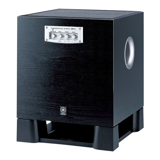
YST-SW315
CONTENTS
TO SERVICE PERSONNEL .......................................... 2
SPECIFICATIONS / 参考仕様 ........................................ 3
INTERNAL VIEW ........................................................... 3
BLOCK DIAGRAM ......................................................... 4
REAR PANELS .......................................................... 4~5
DISASSEMBLY PROCEDURES / 分解手順 ............. 6~7
1 0 0 8 5 5
SUBWOOFER SYSTEM
SERVICE MANUAL
IMPORTANT NOTICE
This manual has been provided for the use of authorized YAMAHA
Retailers and their service personnel.
It has been assumed that basic service procedures inherent to the industry,
and more specifically YAMAHA Products, are already known and
understood by the users, and have therefore not been restated.
WARNING:
Failure to follow appropriate service and safety
procedures when servicing this product may result in
personal injury, destruction of expensive components,
and failure of the product to perform as specified. For
these reasons, we advise all YAMAHA product owners
that any service required should be performed by an
authorized YAMAHA Retailer or the appointed service
representative.
IMPORTANT:
The presentation or sale of this manual to any individual
or firm does not constitute authorization, certification or
recognition of any applicable technical capabilities, or
establish a principle-agent relationship of any form.
The data provided is believed to be accurate and applicable to the unit(s)
indicated on the cover. The research, engineering, and service departments
of YAMAHA are continually striving to improve YAMAHA products.
Modifications are, therefore, inevitable and specifications are subject to
change without notice or obligation to retrofit. Should any discrepancy
appear to exist, please contact the distributor's Service Division.
WARNING:
Static discharges can destroy expensive components.
Discharge any static electricity your body may have
accumulated by grounding yourself to the ground buss in
the unit (heavy gauge black wires connect to this buss).
IMPORTANT:
Turn the unit OFF during disassembly and part
replacement. Recheck all work before you apply power
to the unit.
ADJUSTMENTS / 調整 ............................................ 8~10
PRINTED CIRCUIT BOARD .................................. 11~12
SCHEMATIC DIAGRAM .............................................. 13
PARTS LIST ........................................................... 15~23
P.O.Box 1, Hamamatsu, Japan
Advertisement
Table of Contents

Related Manuals for Yamaha YST-SW315


Summary of Contents for Yamaha YST-SW315
-
Page 1: Table Of Contents
YST-SW315 SERVICE MANUAL IMPORTANT NOTICE This manual has been provided for the use of authorized YAMAHA Retailers and their service personnel. It has been assumed that basic service procedures inherent to the industry, and more specifically YAMAHA Products, are already known and understood by the users, and have therefore not been restated. -
Page 2: To Service Personnel
YST-SW315 AC LEAKAGE TO SERVICE PERSONNEL WALL EQUIPMENT TESTER OR OUTLET UNDER TEST EQUIVALENT 1. Critical Components Information Components having special characteristics are marked s and must be replaced with parts having specifications equal to those originally installed. 2. Leakage Current Measurement (For 120V Models Only) -
Page 3: Specifications / 参考仕様
YST-SW315 SPECIFICATIONS / 参考仕様 Weight / 質量 ........... 19 kg (41 lbs. 14 oz.) Type / 型式 ....Advanced Yamaha Active Servo Technology Output Power / 出力 ....250 W (100 Hz, 5 Ω, 10% T.H.D.) Finish Cherry Color ....... U, C, A, B, G, R, T, K, J models Input Sensitivity / 入力感度... -
Page 4: Block Diagram
YST-SW315 BLOCK DIAGRAM PRE DRIVE VOLUME PHASE Q2—10 POWER DRIVE DRIVER Q1C, 17C, 24A IC11A SELECT Q28, 29 Q16A/C, 26A/C PS AMP B.P .F. Q27, 31 IC11B IC10A – IC7A Q201—204 IC7B IC10B – INPUT 1 – L.P.F. L.P.F. H.P.F. - Page 5 YST-SW315 B, G models R model T model K model J model...
-
Page 6: Disassembly Procedures / 分解手順
YST-SW315 DISASSEMBLY PROCEDURE / 分解手順 (番号順に部品を取り外してください。) (Remove parts in the order as numbered.) Disconnect the power cable from the AC outlet. AC電源コンセントから、電源コードを抜いてください。 1. スピーカーユニットの外し方 1. Removal of Driver a. Remove 4 screws (1) and then remove the Base. (Fig. 1) a. - Page 7 YST-SW315 3. リアパネルAss'yの外し方 3. Removal of Rear Panel Ass'y a. Remove 8 screws (4). (Fig. 3) a. ④のネジ8本を外します。 (Fig. 3) * Screws (4) are identified with arrow marks ( ※ 取り外す④のネジには矢印 ( ) が印刷されています。 b. リアパネルAss'yを引き出します。 (Fig. 3) b. Pull out the rear panel ass'y. (Fig. 3) c.
-
Page 8: Adjustments
YST-SW315 ADJUSTMENTS / 調整 ●パワーアンプの動作の確認 Confirmation of Power Amp operation パワーアンプを修理した場合、下記の手順に従って、回路 For the power amplifier which has been repaired, it is absolutely necessary to confirm that a correct 図に示してある 点と 点で正しい波形が得られることを 必ず確認してください。 waveform is obtained at points indicated by the schematic diagram according to the following procedure. - Page 9 YST-SW315 Idling Adjustment ●アイドリングの調整 To stabilize operation of the amplifier, turn ON the power アンプの動作を安定させるためには、信号を入力しないで with no input signal and wait for 2 to 3 minutes in non 電源を入れ、無負荷の状態で2、3分待ってから調整を行っ loaded condition before the adjustment. てください。 Confirm that the voltage across the terminals TP11 and TP11とTP12の端子間の電圧が10 mV ∼...
- Page 10 YST-SW315 Schematic Diagram / 回路図 POWER DRIVE PS AMP DRIVER IDLING CURRENT DC 10 mV 200 mV Test Points / テストポイント MAIN (1) P.C.B. Point A Point B TP11 (+) TP12 (-) DC 10 mV to 200 mV MAIN (2) P.C.B.
-
Page 11: Printed Circuit Board
YST-SW315 PRINTED CIRCUIT BOARD (Foil side) • Semiconductor Location Ref. No. Location Ref. No. Location MAIN (4) P.C.B. MAIN (2) P.C.B. MAIN ( 10 ) P.C.B. MAIN ( 3 ) P.C.B. Q16A F5 Q16C H5 Q17A G5 Q17C H5 CONFIRMATION OF... - Page 12 YST-SW315 PRINTED CIRCUIT BOARD (Foil side) MAIN (10) P.C.B. MAIN ( 2 ) P.C.B. MAIN ( 5 ) P.C.B. MAIN ( 4 ) P.C.B. MAIN ( 8 ) P.C.B. STANDBY/ON POWER B.A.S.S. STANDBY/ON VOLUME HIGH CUT 150Hz 50Hz MOVIE MUSIC •...
-
Page 13: Schematic Diagram
YST-SW315 SCHEMATIC DIAGRAM IC1: NJM79M12FA Voltage Regulator B.P.F L.P.F COMMON -11.8 POWER DRIVE PS AMP -1.6 PRE DRIVE 70.1 70.1 OUTPUT -0.1 70.1 70.1 11.9 70.1 -0.1 70.1 69.4 69.8 69.4 69.5 70.0 69.6 70.1 69.6 70.1 69.7 69.3 69.8 69.8... -
Page 14: Parts List
YST-SW315 PARTS LIST ELECTRICAL PARTS WARNING Components having special characteristics are marked s and must be replaced with parts having specifications equal to those originally installed. ●s印のある部分は、 安全確保部品を示 しています。 部品の交換が必要な場合、 パーツ リ ス トに記載されている部品を使用 して く ださい。 ●部品価格ランクは、 予告な く 変更するこ とがあ り ます。... - Page 15 YST-SW315 P.C.B. MAIN Schm Ref. PART NO. Description Remarks Markets 部 品 名 Rank WB373300 P.C.B. MAIN PCB MAIN WB373400 P.C.B. MAIN PCB MAIN WB373500 P.C.B. MAIN PCB MAIN WB373600 P.C.B. MAIN PCB MAIN WB373700 P.C.B. MAIN PCB MAIN VB389900 CN.BS.PIN ベースピン VB390600 CN.BS.PIN コネクタベースポスト 01 VB858800 CN.BS.PIN ベースピン...
- Page 16 YST-SW315 P.C.B. MAIN Schm Ref. PART NO. Description Remarks Markets 部 品 名 Rank UA655100 C.MYLAR 0.1uF マイラーコン UA654220 C.MYLAR 0.022uF マイラーコン UA654220 C.MYLAR 0.022uF マイラーコン UR798330 C.EL 330uF 100V ケミコン FG644100 C.CE 0.01uF セラコン FG644100 C.CE 0.01uF セラコン UA654100 C.MYLAR 0.01uF マイラーコン...
- Page 17 YST-SW315 P.C.B. MAIN Schm Ref. PART NO. Description Remarks Markets 部 品 名 Rank C242 FG644100 C.CE 0.01uF セラコン C243 FG644100 C.CE 0.01uF セラコン s D1 VQ111400 DIODE.BRG D5SBA20-4001 6A ダイオードブリッジ s D2 VR253700 DIODE.BRG S1NB20 1A 200V DIブリッジ X4 VD631600 DIODE 1SS133,176 ダイオード...
- Page 18 YST-SW315 P.C.B. MAIN Schm Ref. PART NO. Description Remarks Markets 部 品 名 Rank IC201 X2020A00 IC LB8555D アンプIC SIL 04 IC202 X4472A00 IC NJM78L08A-T3 電源IC V8426000 COIL 120uH BCS10-03060 コイル 120u V8426000 COIL 120uH BCS10-03060 コイル 120u VU038200 COIL 0.95uH コイル V6415800 JACK.PIN ピンジャック 2P G 03...
- Page 19 YST-SW315 P.C.B. MAIN Schm Ref. PART NO. Description Remarks Markets 部 品 名 Rank V7093700 R.MTL.OXD 1.8KΩ 酸化金属被膜抵抗 HB027100 R.MTL.FLM 10KΩ 1/4W 金属被膜抵抗 HB027100 R.MTL.FLM 10KΩ 1/4W 金属被膜抵抗 HB027100 R.MTL.FLM 10KΩ 1/4W 金属被膜抵抗 HV753470 R.CAR.FP 4.7Ω 1/4W 不燃化カーボン抵抗 VG730500 R.MTL.OXD 0.15Ω 酸化金属被膜抵抗...
- Page 20 YST-SW315 Parts List for Carbon Resistors P.C.B. MAIN Value 1/4W Type Part No. 1/6W Type Part No. Value 1/4W Type Part No. 1/6W Type Part No. Schm 1.0 Ω 3100 3100 10 kΩ 7100 7100 HJ35 HF85 HF45 HF45 Ref.
- Page 21 YST-SW315 EXPLODED VIEW MECHANICAL PARTS Rear Panel Ass'y Schm リアパネルAss'y Ref. PART NO. Description Remarks Markets 部 品 名 Rank WB373800 CABINET ASS'Y キャビネットASSY WB373900 CABINET ASS'Y キャビネットASSY X4457A00 DRIVER, WOOFER 25cm 6Ω JA2564 スピーカーユニット WB248400 FRONT PANEL フロントパネル U, C models only...
- Page 22 YST-SW315 EXPLODED VIEW (REAR PANEL ASS’Y) MECHANICAL PARTS (REAR PANEL ASS’Y) Schm Ref. PART NO. Description Remarks Markets 部 品 名 Rank 4-1-1 (3) 4-1-1 WB373300 PCB ASS'Y MAIN PCB MAIN 4-1-1 WB373400 PCB ASS'Y MAIN PCB MAIN 4-1-1 WB373500 PCB ASS'Y MAIN PCB MAIN...
- Page 23 YST-SW315...