Table of Contents
Advertisement
OWNER'S MANUAL
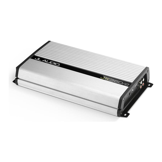
360W 2-Channel, Full-Range Amplifier
Thank you for purchasing a JL Audio amplifier for
your automotive sound system.
Your amplifier has been designed and manufactured to exacting
standards in order to ensure years of musical enjoyment in your vehicle.
For maximum performance, we highly recommend that you have
your new amplifier installed by an authorized JL Audio dealer. Your
authorized dealer has the training, expertise and installation equipment
to ensure optimum performance from this product. Should you
decide to install the amplifier yourself, please take the time
to read this manual thoroughly so as to familiarize yourself
with its installation requirements and setup procedures.
If you have any questions regarding the instructions in this
manual or any aspect of your amplifier's operation, please contact your
authorized JL Audio dealer for assistance. If you need further assistance,
please call our Technical Support Department
at (954) 443-1100 during business hours.
Advertisement
Table of Contents

Summary of Contents for JL Audio JX360/2
- Page 1 For maximum performance, we highly recommend that you have your new amplifier installed by an authorized JL Audio dealer. Your authorized dealer has the training, expertise and installation equipment to ensure optimum performance from this product.
-
Page 2: Protect Your Hearing
Frequency Selector Input Jack Preamp Output Jacks (pg. 11) (pg. 8) (pg. 6) (pg. 9) Protection Filter Mode Input Sensitivity Left & Right Status Indicator Selector Control Preamp Input Jacks (pg. 11) (pg. 8) (pg. 7) (pg. 6) JL Audio... -
Page 3: Installation Applications
Stupid Mistakes to Avoid Cooling Efficiency Considerations: Check before drilling any holes in your vehicle The outer shell of your JL Audio amplifier is to make sure that you will not be drilling designed to remove heat from the amplifier through a gas tank, brake line, wiring harness or circuitry. -
Page 4: Product Description
Class A/B technology. 6) Find a good, solid metal grounding point The JX360/2 can be operated with a wide close to the amplifier and connect the variety of source units and system configurations. negative power wire to it using appropriate For detailed specifications, please refer to hardware. -
Page 5: Power Connections
If the distribution block mounted as close to the JX360/2 is the only device connected to this main amplifiers as possible and should connect to the wire, use a 50A AGU or MAXI® fuse (no other JX360/2 with 4 AWG power wire. -
Page 6: Turn-On Lead
TURN-ON LEAD INPUT SECTIONS The JX360/2 is turned on and off The JX360/2’s has one pair of stereo inputs.The input section input section on lead, typically controlled by the offers two input connection methods, one source unit’s remote turn-on output. -
Page 7: Input Sensitivity Control
(quieter for a given harness into the “Hi-Level Inputs” connectors input voltage.) on the amplifier. The JX360/2 will attenuate the high-level signals to make them compatible with its input stage. IMPORTANT Make sure you observe correct polarity in making the “Hi-Level Input”... -
Page 8: Filter Controls
The filter in the JX360/2 is fully variable between 50 Hz and 200 Hz. The "80" Hz position is a good starting point for tuning systems utilizing typical subwoofers and component or coaxial speakers. - Page 9 PREOUTS The JX360/2 incorporates a pass-through preamp amplifiers can be easily added to the system. This pass-through pre-amp output delivers the same signals that are fed into the amplifier's Low-Level inputs. Input signals applied to the High-Level The preamp output signal is not affected by the “Bass Boost”...
-
Page 10: Speaker Outputs
The combined output of the two channels when using a the JX360/2 to drive a subwoofer provides twice the output voltage available from system or a summed mono center channel. -
Page 11: Servicing Your Amplifier
JL Audio dealer so control panel of the amplifier. that it may be sent in to JL Audio for service. There are no user serviceable parts or fuses inside the amplifier. The unique nature of the circuitry in the JL Audio amplifiers requires specifically trained service personnel. - Page 12 (within the frequency range to be amplified) at 3/4 source unit volume. 7) Connect the AC voltmeter to the speaker output connectors of the amplifier. Make sure you test JL Audio...
- Page 13 APPENDIX B: JX360/2 Specifications Amplifier Section: Amplifier Topology: Class A/B Power Supply: Unregulated PWM switching type Frequency Response: 20 Hz - 20 kHz +0/-1 dB Signal to Noise Ratio: >100 dBA referred to highest rated power per ch., >77 dBA referred to 1W (20 Hz - 20 kHz Bandwidth) Damping Factor: >60 @ 4 ohms per ch.
-
Page 14: Appendix C: Troubleshooting
Check the input connectors to ensure that they all are making good contact with the input jacks on the amplifier. JL Audio... - Page 15 The speaker wire connectors are designed to accept up to 8 AWG wire. Make sure to strip the wire to allow for a sufficient connection with the metal inside the terminal block. JX360/2...
- Page 16 INSTALLATION NOTES: Use this diagram to document your amplifier’s switch and control positions. JL Audio JX360/2...
- Page 17 LIMITED WARRANTY - AMPLIFIERS (USA) JL Audio warrants this product to be free of defects in materials and workmanship for a period of one (1) year from the original date of purchase. This warranty is not transferrable and applies only to the original purchaser from an authorized JL Audio dealer.


