Table of Contents
Advertisement
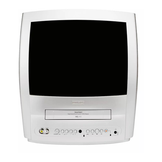
TV-VCR Combination
Service
Service
Service
Service Manual
Contents
Chapter
Sec. 1:
Adjustment Procedure
Schematic Diagrams and CBA's
Exploded Views
Mechanical and Electrical Parts Lists
Sec. 2: Standard Maintenance
Mechanism Alignment Procedures
Disassembly / Assembly of Mechanism
Deck Exploded Views
For technical data reference is made to the Service Manual of
14PV374/01/07/39/58 & 14PV375/01/07/39/58 3103 785 22220.
The present Manual states only the differences.
Safety regulations require that the set be restored to its original
condition and that parts which are identical with those specified
be used.
Published by BK 2003 Video Service Department
14PV120
14PV125
14PV225
14PV422
14PV425
Survey of versions:
/01
PAL-BG, EURO
/07
PAL I, UK/IRELAND
/39
PAL/SECAM-BG+PAL/SECAM-L/L',FRANCE
/58
PAL-BG/DK+SECAM-BG/DK,EAST-EURO
Printed in Japan
c Copyright reserved
/07
/01/07/39/58
/01/07/39/58
/01/07/39/58
/07
Subject to modification
GB
3103 785 22230
Advertisement
Table of Contents

Related Manuals for Philips 14PV120


Summary of Contents for Philips 14PV120
- Page 1 TV-VCR Combination Service 14PV120 Service 14PV125 /01/07/39/58 14PV225 Service /01/07/39/58 14PV422 /01/07/39/58 14PV425 Service Manual Contents Survey of versions: PAL-BG, EURO Chapter PAL I, UK/IRELAND PAL/SECAM-BG+PAL/SECAM-L/L',FRANCE Sec. 1: Adjustment Procedure PAL-BG/DK+SECAM-BG/DK,EAST-EURO Schematic Diagrams and CBA's Exploded Views Mechanical and Electrical Parts Lists Sec.
-
Page 2: Operating Controls And Functions
OPERATING CONTROLS AND FUNCTIONS [ 14PV120/07, 14PV125/ ( 01, 07, 39, 58 ), 14PV225/ ( 01, 07, 39, 58 ), 14PV422/ ( 01, 07, 39, 58 ), 14PV425/07 ] 1-4-3 T6410IB... - Page 3 1-4-4 T6410IB...
- Page 4 BLOCK DIAGRAMS [ 14PV120/07, 14PV125/ (01, 07, 39, 58), 14PV225/ (01, 07, 39, 58), 14PV422/ ( 01, 07, 39, 58 ), 14PV425/07 ] Comparison Chart of Servo/System Control Block Diagram NOTE FOR WIRE CONNECTORS: Models & Marks TEST POINT INFORMATION 1.
-
Page 5: Video Block Diagram
FROM /TO 14PV422/01 SERVO/SYSTEM 14PV422/58 CONTROL BLOCK 14PV422/39 C-VIDEO TO CHROMA BLOCK 14PV125/07 14PV125/01 TU001 14PV125/58 VIDEO OUT 14PV125/39 14PV125/39 14PV120/07 IC401 14PV425/07 (VIDEO/AUDIO SIGNAL PROCESS) (DECK ASSEMBLY) SERIAL Y. DELAY DECORDER JK701 CYLINDER ASSEMBLY V-IN CL401 V(R) VIDEO (R) LUMINANCE... -
Page 6: Audio Block Diagram
Audio Block Diagram NOTE FOR WIRE CONNECTORS: TEST POINT INFORMATION 1. PREFIX SYMBOL "CN" MEANS CONNECTOR. :INDICATES A TEST POINT WITH A JUMPER WIRE ACROSS A HOLE IN THE PCB. (CAN DISCONNECT AND RECONNECT.) :USED TO INDICATE A TEST POINT WITH A COMPONENT LEAD ON FOIL SIDE. 2. - Page 7 DATA SLICER CN901 CN751 14PV422/58 Y-SW-OUT DISPLAY 14PV422/39 V-SYNC TIMING 14PV125/07 H-SYNC 14PV125/01 C I/F 14PV125/58 14PV125/39 14PV125/39 CN902 CN752 14PV120/07 OSD-BLK 14PV425/07 TELETEXT OSD-B DECODER OSD-G OSD-R X901 SERIAL OSC/CLOCK 12MHz GENERATOR INTELLIGENT TEXT CBA MONITORING LINE/PB CN303 VIDEO...
- Page 8 CRT/H.V. Block Diagram NOTE FOR WIRE CONNECTORS: TEST POINT INFORMATION 1. PREFIX SYMBOL "CN" MEANS CONNECTOR. :INDICATES A TEST POINT WITH A JUMPER WIRE ACROSS A HOLE IN THE PCB. (CAN DISCONNECT AND RECONNECT.) :USED TO INDICATE A TEST POINT WITH A COMPONENT LEAD ON FOIL SIDE. 2.
-
Page 9: Power Supply Block Diagram
Power Supply Block Diagram CAUTION ! NOTE : Fixed voltage power supply circuit is used in this unit. CAUTION The voltage for parts in hot circuit is measured using If Main Fuse (F601) is blown, check to see that all components in the power supply FOR CONTINUED PROTECTION AGAINST FIRE HAZARD, hot GND as a common terminal. - Page 10 [14PV120/07,14PV125/(01,07,39,57),14PV225/(01,07,39,57),14PV422/ (01,07,39,57),14PV425/07 ] Main 1/5 Schematic Diagram Parts Location Guide Ref No. Position Ref No. Position Ref No. Position Ref No. Position CAPACITORS CONNECTOR RESISTORS RESISTORS C203 CN201 R220 R268 DIODES C205 R221 R269 C207 D201 R222 R270 C208 D202...
- Page 11 MODEL MARK “ “ = SMD THE SAME VOLTAGE FOR INDICATES THAT THE VOLTAGE 14PV225/07 BOTH PLAY & REC MODES. IS NOT CONSISTENT HERE. 14PV225/01 14PV225/58 14PV225/39 14PV422/07 14PV422/01 14PV422/58 14PV422/39 14PV125/07 14PV125/01 14PV125/58 14PV125/39 14PV120/07 14PV425/07 1-8-44 1-8-45 T6410SCM1...
- Page 12 Main 2/5 Schematic Diagram Voltage indications for PLAY and REC modes on the Schematic Diagrams are as shown below: PLAY MODE REC MODE “ “ = SMD (2.5) THE SAME VOLTAGE FOR INDICATES THAT THE VOLTAGE BOTH PLAY & REC MODES. IS NOT CONSISTENT HERE.
- Page 13 Main 2/5 Schematic Diagram Parts Location Guide Ref No. Position Ref No. Position Ref No. Position Ref No. Position CAPACITORS CAPACITORS COILS RESISTORS C401 C443 L402 R851 C402 C444 L403 R852 C403 C445 L852 R853 C404 C452 L854 R854 TRANSISTORS C405 C851 R856...
- Page 14 Main 3/5 Schematic Diagram Parts Location Guide Ref No. Position Ref No. Position Ref No. Position CAPACITORS CAPACITORS RESISTORS C001 C333 R156 C002 C334 R301 C006 C336 R302 C007 C338 R303 C008 C339 R304 C009 C340 R305 C012 C341 R306 C151 C344 R307...
- Page 15 Voltage indications for PLAY and REC modes on Main 3/5 Schematic Diagram the Schematic Diagrams are as shown below: PLAY MODE REC MODE “ “ = SMD (2.5) THE SAME VOLTAGE FOR INDICATES THAT THE VOLTAGE BOTH PLAY & REC MODES. IS NOT CONSISTENT HERE.
- Page 16 BOTH PLAY & REC MODES. IS NOT CONSISTENT HERE. Q682 Q684 Q685 Q686 “ “ = SMD Comparison Chart of Models and Marks MODEL MARK 14PV225/07 14PV225/01 14PV225/58 14PV225/39 14PV422/07 14PV422/01 14PV422/58 14PV422/39 14PV125/07 14PV125/01 14PV125/58 14PV125/39 14PV120/07 14PV425/07 T6410SCM4 1-8-52 1-8-53...
- Page 17 Main 4/5 Schematic Diagram Parts Location Guide Ref No. Position Ref No. Position CAPACITORS DIODES C471 D688 C472 D690 C473 D691 C474 D693 C475 D694 C476 C478 IC471 C479 IC681 COILS C480 C481 L681 C483 L682 TRANSISTORS C484 C485 Q682 C486 Q684 C681...
- Page 18 Main 5/5 Schematic Diagram Parts Location Guide Ref No. Position Ref No. Position CAPACITORS RESISTORS BB-2 C701 R705 BB-2 AA-4 C703 R707 CC-4 CC-4 C705 R709 CC-4 BB-4 C706 R710 AA-4 AA-3 C707 R711 BB-4 CC-4 C708 R712 BB-4 CC-4 C709 R714 CC-4...
- Page 19 Voltage indications for PLAY and REC modes on Main 5/5 Schematic Diagram the Schematic Diagrams are as shown below: PLAY MODE “ “ = SMD REC MODE (2.5) THE SAME VOLTAGE FOR INDICATES THAT THE VOLTAGE BOTH PLAY & REC MODES. IS NOT CONSISTENT HERE.
-
Page 20: Wiring Diagram
P-ON-L 14PV125/07 Y-SW-OUT AL+12V(2) AL+12V(2) JUNCTION-A CBA 14PV125/01 AL+9V AL+9V BT6300F01011 TEXT CBA 14PV125/58 AL+9V BT6400F01031 14PV125/39 14PV125/39 TEXT-RESET 14PV120/07 AL+33V AL+33V CN752 CN902 14PV425/07 P-ON+8V P-ON+8V P-SAFETY 2 PROTECT PROTECT OSD-BLK OSD-R W601 OSD-B PROTECT OSD-G M, N, O, P... -
Page 21: Ic Pin Function Descriptions
IC PIN FUNCTION DESCRIPTIONS [ 14PV120/07, 14PV125/ ( 01, 07, 39, 58 ), 14PV225/ ( 01, 07, 39, 58 ), 14PV422/ ( 01, 07, 39, 58 ), 14PV425/07 ] Comparison Chart of Models and Marks Signal Mark Function Name Model... - Page 22 Signal Signal Mark Function Mark Function Name Name M,N, OUT RGB-CONT RGB Control Signal O,Q, OUT OSD-B Blue Output R,S, Not Used OUT OSD-G Green Output U,V, W,Y, OUT OSD-R Red Output RAPID-Switch Input RAPIT-SW-IN Special Playback = Signal P,T,X OUT TRICK-H “H”...
- Page 23 Signal Mark Function Name Capstan Motor C-FG Rotation Detection Pulse AMPVss AMPVss (GND) Not Used Drum Motor Phase/ D-PFG Frequency Generator AMP VREF- Standard Voltage Output AMP VREF- Standard Voltage Input C Terminal CTL (-) CTL (-) CTL (+) CTL (+) AMPC AMPC CTL AMP-...
-
Page 24: Lead Identifications
LEAD IDENTIFICATIONS [ 14PV120/07, 14PV125/ ( 01, 07, 39, 58 ), 14PV225/ ( 01, 07, 39, 58 ), 14PV422/ ( 01, 07, 39, 58 ), 14PV425/07 ] TT2084LS-YB11 PT204-6B-12 TT2138LS-YB11 2SK2647 MID-32A22 2SD1913(R) 2SC5884000RF KTC2026Y S: Souce E: Emitter D: Drain... - Page 25 PRODUCT SAFETY NOTE: Products marked with a h have special characteristics important to safety. Before replacing any of these components, read carefully the product safety notice in this service manual. Don’t degrade the safety of the product through improper servicing. NOTES: C…..±0.25% D…..±0.5%...
- Page 26 ELECTRICAL PARTS LIST h 12 NC Pos. Description C222 CHIP CERAMIC CAP.(MELF) F Z 0.01UF/16V C223 CHIP CERAMIC CAP.(MELF) Y K 2200PF/35V 1 C224 CHIP CERAMIC CAP. F Z 0.1UF/50V C225 CHIP CERAMIC CAP. CH J 560PF/50V C226 CHIP CERAMIC CAP. F Z 0.1UF/50V C227 CHIP CERAMIC CAP.
- Page 27 ELECTRICAL PARTS LIST h 12 NC Pos. Description C338 CHIP CERAMIC CAP.(MELF) Y K 1000PF/35V 1 C339 CHIP CERAMIC CAP.(MELF) F Z 0.01UF/16V C340 CHIP CERAMIC CAP.(MELF) SL J 100PF/50V C341 CHIP CERAMIC CAP.(MELF) F Z 0.01UF/16V C344 CHIP CERAMIC CAP.(MELF) Y K 1000PF/35V 1 C350 ELECTROLYTIC CAP.
- Page 28 ELECTRICAL PARTS LIST h 12 NC Pos. Description C486 ELECTROLYTIC CAP. 2.2UF/50V M H7 C681 ELECTROLYTIC CAP. 220UF/16V M C682 ELECTROLYTIC CAP. 220UF/16V M C683 ELECTROLYTIC CAP. 10UF/50V M C684 CHIP CERAMIC CAP.(MELF) SL J 100PF/50V C687 ELECTROLYTIC CAP. 47UF/25V M C688 ELECTROLYTIC CAP.
- Page 29 ELECTRICAL PARTS LIST h 12 NC Pos. Description CN302 9965 000 13916 CONNECTOR, 8P TUC-P08X-B1 CN303 9965 000 13841 CONNECTOR BASE, 5P TUC-P05P-B1 CN603 9965 000 18089 CONNECTOR 13P TUC-P13X-B1 CN751 9965 000 13842 CONNECTOR BASE, 8P TUC-P08P-B1 CN752 9965 000 13843 CONNECTOR BASE, 6P TUC-P06P-B1 CN804 9965 000 13844...
- Page 30 ELECTRICAL PARTS LIST h 12 NC Pos. Description J418F3 9965 000 05627 CHOKE COIL 47UH-K L151 9965 000 18094 INDUCTOR 1.8UH-J-26T L152 9965 000 13856 INDUCTOR 1.0UH-J-26T L201 9965 000 13857 INDUCTOR 0.10UH-K-26T L302 9965 000 13858 INDUCTOR 33UH-J-26T L303 PCB JUMPER D0.6-P7.5 L304 PCB JUMPER D0.6-P7.5...
- Page 31 ELECTRICAL PARTS LIST h 12 NC Pos. Description R205 CARBON RES. 1/4W J 1K OHM R206 CHIP RES.(1608) 1/10W J 390K OHM R207 CHIP RES.(1608) 1/10W J 10K OHM R208 CHIP RES.(1608) 1/10W J 1.5K OHM R209 CHIP RES.(1608) 1/10W J 1.5K OHM R210 CARBON RES.
- Page 32 ELECTRICAL PARTS LIST h 12 NC Pos. Description R271 CHIP RES.(1608) 1/10W J 10K OHM R272 CHIP RES.(1608) 1/10W J 18K OHM R273 CHIP RES.(1608) 1/10W J 18K OHM R274 CHIP RES.(1608) 1/10W J 10K OHM R275 CHIP RES.(1608) 1/10W J 560 OHM R276 CHIP RES.(1608) 1/10W J 1.5K OHM R277...
- Page 33 ELECTRICAL PARTS LIST h 12 NC Pos. Description R413 CHIP RES.(1608) 1/10W J 2.2K OHM R414 CHIP RES.(1608) 1/10W J 6.8K OHM R415 CHIP RES.(1608) 1/10W J 4.7K OHM R416 CHIP RES.(1608) 1/10W J 1.2K OHM R417 CHIP RES.(1608) 1/10W J 10K OHM R418 CHIP RES.(1608) 1/10W J 56K OHM R420...
- Page 34 ELECTRICAL PARTS LIST h 12 NC Pos. Description R744 CHIP RES.(1608) 1/10W J 47K OHM R745 CHIP RES.(1608) 1/10W J 6.2K OHM R746 CHIP RES.(1608) 1/10W J 47K OHM R747 CHIP RES.(1608) 1/10W J 6.2K OHM R748 CHIP RES.(1608) 1/10W J 1.8K OHM R749 CHIP RES.(1608) 1/10W J 10K OHM R750...
- Page 35 ELECTRICAL PARTS LIST h 12 NC Pos. Description TP006 PCB JUMPER D0.6-P10.0 TP007 PCB JUMPER D0.6-P10.0 TP008 PCB JUMPER D0.6-P12.5 TP009 PCB JUMPER D0.6-P12.5 TP010 PCB JUMPER D0.6-P22.5 X201 9965 000 09200 X’TAL 32.768KHZ(20PPM) X202 9965 000 12194 X’TAL 12.000MHZ X301 9965 000 13869 X’TAL 4.433619MHZ...
- Page 36 ELECTRICAL PARTS LIST h 12 NC Pos. Description C609 CERAMIC CAP. 0.01UF/AC250V C610 CERAMIC CAP. 0.01UF/AC250V C611 ELECTROLYTIC CAP. 100UF/400V M C613 FILM CAP.(P) 0.039UF/50V J C614 FILM CAP.(P) 0.0012UF/50V J C615 FILM CAP.(P) 0.068UF/50V J C616 CERAMIC CAP. R K 220PF/2KV(HR) C617 ELECTROLYTIC CAP.
- Page 37 ELECTRICAL PARTS LIST h 12 NC Pos. Description D621 9965 000 13886 DIODE 1ZC33 D622 4822 130 32778 SWITCHING DIODE 1SS133(T-77) D623 4822 130 32778 SWITCHING DIODE 1SS133(T-77) D624 4822 130 32778 SWITCHING DIODE 1SS133(T-77) D625 4822 130 11629 ZENER DIODE MTZJT-776.8B D626 9965 000 13885 FAST RECOVERY DIODE CA201-4...
- Page 38 ELECTRICAL PARTS LIST h 12 NC Pos. Description R558 CARBON RES. 1/4W J 4.7 OHM R559 CARBON RES. 1/4W J 4.7 OHM R560 CARBON RES. 1/4W J 4.7 OHM R561 CARBON RES. 1/4W J 4.7 OHM R564 CARBON RES. 1/4W J 8.2K OHM R565 PCB JUMPER D0.6-P5.0 R566...
- Page 39 ELECTRICAL PARTS LIST h 12 NC Pos. Description R638 CARBON RES. 1/4W J 39K OHM R639 CARBON RES. 1/4W J 39K OHM R640 CARBON RES. 1/4W J 2.7K OHM R641 CARBON RES. 1/2W J 1K OHM R642 CARBON RES. 1/4W J 10K OHM R643 CARBON RES.
- Page 40 ELECTRICAL PARTS LIST h 12 NC Pos. Description R503 METAL OXIDE FILM RES. 1W J 18K OHM R504 CARBON RES. 1/4W J 1.5K OHM R505 CARBON RES. 1/4W J 1.5K OHM R506 CARBON RES. 1/4W J 1.5K OHM R507 CARBON RES. 1/4W J 1.5K OHM R510 CARBON RES.
- Page 41 ELECTRICAL PARTS LIST h 12 NC Pos. Description Q901 TRANSISTOR KTC3198(GR) Q901 TRANSISTOR 2SC1815-GR(TPE2) RESISTORS R901 CARBON RES. 1/4W J 2.2K OHM R902 CARBON RES. 1/4W J 1K OHM R903 CARBON RES. 1/4W J 24K OHM R904 CARBON RES. 1/4W J 10K OHM R905 CARBON RES.
-
Page 42: Mechanical Parts List
A1-7 MECHANICAL PARTS LIST Pos. Pos. Expl. View 12 NC Description 0001 *) 3143 027 60281 FRONT ASSY 14PV120/07 0001 *) 3143 027 60291 FRONT ASSY 14PV125/01/07/58 0001 *) 3143 027 60301 FRONT ASSY 14PV125/39 0001 *) 3143 027 60041... - Page 43 9965 000 12171 M3X8 BIND HEAD+ SCREW, P-TIGHT TL18 9965 000 13027 M3X8 BIND HEAD+ PACKING 0450 S1 BOX FOLDED 14PV120 0450 S1 BOX FOLDED 14PV125 0450 S1 BOX FOLDED 14PV22X 0450 S1 BOX FOLDED 14PV42X 0453 S2 STYROFOAM TOP A...
-
Page 44: Standard Maintenance
STANDARD MAINTENANCE [ 14PV120/07, 14PV125/ ( 01, 07, 39, 58 ), 14PV225/ ( 01, 07, 39, 58 ), 14PV422/ ( 01, 07, 39, 58 ), 14PV425/07 ] Service Schedule of Components H: Hours : Check I: Change Deck Periodic Service Schedule Ref.No. - Page 45 Cleaning Cleaning of Audio Control Head Clean the head with a cotton swab. Cleaning of Video Head Procedure Clean the head with a head cleaning stick or chamois 1.Remove the top cabinet. cloth. 2.Dip the cotton swab in 90% isopropyl alcohol and Procedure clean the audio control head.
-
Page 46: Service Fixture And Tools
SERVICE FIXTURE AND TOOLS [ 14PV120/07, 14PV125/ ( 01, 07, 39, 58 ), 14PV225/ ( 01, 07, 39, 58 ), 14PV422/ ( 01, 07, 39, 58 ), 14PV425/07 ] J-1-1, J-1-2 Ref. No. Name Part No. Adjustment J-1-1 Alignment Tape... -
Page 47: Mechanical Alignment Procedures
MECHANICAL ALIGNMENT PROCEDURES [ 14PV120/07, 14PV125/ ( 01, 07, 39, 58 ), 14PV225/ ( 01, 07, 39, 58 ), 14PV422/ ( 01, 07, 39, 58 ), 14PV425/07 ] Explanation of alignment for the tape to correctly run B. Method to place the Cassette Holder in the tape- starts on the next page. -
Page 48: Tape Interchangeability Alignment
1.Tape Interchangeability Alignment Note: To do these alignment procedures, make sure that the Tracking Control Circuit is set to the center position every time a tape is loaded or unloaded. (Refer to page 2-3-8, procedure 1-C, step 2.) Equipment required: Dual Trace Oscilloscope VHS Alignment Tape (FL6N8) Guide Roller Adj. - Page 49 1-A. Preliminary/Final Checking and 3. Check to see that the tape runs without creasing at Alignment of Tape Path Take-up Guide Post [4] or without snaking between Guide Roller [3] and AC Head. (Fig. M3 and M5) Purpose: 4. If creasing or snaking is apparent, adjust the Tilt To make sure that the tape path is well stabilized.
- Page 50 6. Press CH DOWN button on the unit until the CTL Dropping envelope level at the end of track. waveform has shifted from its original position (not the position achieved in step 5, but the position of CTL waveform in step 4) by approximately -2msec. Make sure that the envelope is simply attenuated (shrinks in height) once CTL waveform passes its original position and is further brought in the minus...
-
Page 51: Disassembly / Assembly Procedures Of Deck Mechanism
DISASSEMBLY/ASSEMBLY PROCEDURES OF DECK MECHANISM [ 14PV120/07, 14PV125/ ( 01, 07, 39, 58 ), 14PV225/ ( 01, 07, 39, 58 ), 14PV422/ ( 01, 07, 39, 58 ), 14PV425/07 ] Before following the procedures described below, be sure to remove the deck assembly from the cabinet. (Refer to CABINET DISASSEMBLY INSTRUCTIONS.) - Page 52 REMOVAL INSTALLATION STEP START- REMOVE/*UNHOOK/ /LOC. PART ADJUSTMENT Fig. No. UNLOCK/RELEASE/ CONDITION UNPLUG/DESOLDER [31] [25] BT Arm DM2,DM14 *(P-6) Loading Arm (SP) (+)Refer to Alignment [32] [25] DM2,DM14 Assembly Sec.Pg.2-4-17 Loading Arm (TU) (+)Refer to Alignment [32] [33] DM2,DM14 Assembly Sec.Pg.2-4-17 [34] [2],[25] M Brake (TU) Assembly...
- Page 53 Top View [41] [42] [46] [43] [14] [13] [11] [15] [36] [10] [12] [35] [34] [40] [29] [30] [16] [39] [38] Fig. DM1 Bottom View [20] [33] [32] [24] [26] [27] [25] [23] [28] [22] [21] [31] Fig. DM2 2-4-11 T6410DA...
- Page 54 (S-1) (S-1) (L-1) (L-3) (L-2) (P-1) Fig. DM5 [46] Fig. DM3 [47] Pin D (L-14) Pin C Pull up Slide Pin A Pin B Slot A (S-2) Slots B Slot A First, while pushing the locking tab as shown at right, slide and pull up the right side on [2] to release Pin A and Pin B from the slots A.
- Page 55 (S-4) (S-5) [14] (S-6) [16] [15] Desolder from bottom (S-3) Lead with White Stripe Belt View for A Fig. DM7 Fig. DM9 Adj. Screw [11] [18] (L-4) (L-5) (P-3) [17] [13] [19] [12] (P-4) [10] (P-2) (S-7) Pin of [12] Pin of [10] Fig.
- Page 56 [22] (C-4) (S-8) (C-1) [23] (L-6) [21] (P-5) [20] Cap Belt (P-5) [28] Fig. DM11 When installing [23], install the spring (P-5) to [28] as shown in the left figure, and then install [23] while Pin on pressing the spring (P-5) to bottom the direction of the arrow in of [23]...
- Page 57 (P-6) [25] [31] Refer to the Alignment (C-3) Section, Page 2-4-17. (S-9) [29] [33] [30] (L-11) [32] (L-10) (L-8) (C-2) [27] [28] [24] [26] (L-9) Fig. DM14 [36] Position of Mode Lever when installed Break belt Pin of [35] (P-7) Pin of [31] Pin of [34] [34]...
- Page 58 [42] [41] [43] (L-13) Fig. DM16 (P-9) [44] [45] Slide Fig. DM17 2-4-16 T6410DA...
-
Page 59: Alignment Procedures Of Mechanism
ALIGNMENT PROCEDURES OF MECHANISM [ 14PV120/07, 14PV125/ ( 01, 07, 39, 58 ), 14PV225/ ( 01, 07, 39, 58 ), 14PV422/ ( 01, 07, 39, 58 ), 14PV425/07 ] The following procedures describe how to align the Alignment 1 individual gears and levers that make up the tape... -
Page 60: Deck Exploded Views
DECK EXPLODED VIEWS [ 14PV120/07, 14PV125/ ( 01, 07, 39, 58 ), 14PV225/ ( 01, 07, 39, 58 ), 14PV422/ ( 01, 07, 39, 58 ), 14PV425/07 ] Deck Mechanism View 1 Mark Description Floil G-684G or Multemp MH-D (Blue grease) - Page 61 Deck Mechanism View 2 Mark Description Floil G-684G or Multemp MH-D (Blue grease) B587 B521 B487 SLIDUS OIL #150 B416 B591 SANKOUL FG84M (Yellow grease) B520 B590 B522 B499 L1406 B148 B508 B573 B592 B574 B558 B564 B557 B414 B565 B525 L1151 B417...
- Page 62 Deck Mechanism View 3 Mark Description Floil G-684G or Multemp MH-D (Blue grease) SLIDUS OIL #150 L1321 B347 L1321 B355 B354 B483 B425 B482 B562 B300 B563 B313 B529 B360 B359 B361 B555 B561 B303 Some Ref. Numbers are not in sequence. B514 2-5-6 T6410DEX...
- Page 63 DECK PARTS LIST DECK PARTS LIST Pos. 12 NC Description Pos. 12 NC Description CYLINDER ASS. 996500017189 B525 996500012230 LDG BELT MK11 MK12 PAL 2HD 2SP 996500017217 LOADING MOTOR B529 996500008504 CLEANER ASS. MK10 996500017191 PULLEY ASS. MK12 B553 996500012233 REV SPRING MK11 996500016632 MOVING GUIDE S PREP.