Panasonic KV-S2065L Service Manual
Hide thumbs
Also See for KV-S2065L:
- Service manual (396 pages) ,
- Operating instructions manual (54 pages) ,
- Service manual (20 pages)

Related Manuals for Panasonic KV-S2065L


Summary of Contents for Panasonic KV-S2065L
- Page 1 ORDER NO. KM70104623C0 High Speed Scanner KV-S2065L KV-S2065W © 2001 Kyushu Matsushita Electric Co., Ltd. All rights reserved. Unauthorized copying distribution is a violation of law.
-
Page 2: Table Of Contents
KV-S2065L / KV-S2065W CONTENTS Page Page 1 GENERAL PRECAUTIONS 13.4. SCSI Board (Solder Side) 1.1. Safety Precautions 13.5. MOTHER Board 1.2. Electrical Tests 13.6. DRIVE Board (Component Side) 1.3. For Service Technicians 13.7. DRIVE Board (Solder Side) 2 SPECIFICATION 13.8. PANEL Board 3 COMPONENT IDENTIFICATION 13.9. - Page 3 KV-S2065L / KV-S2065W 16.12. ENDING ( REAR ) SENSOR Board 16.18. ENDING (FRONT) SENSOR Board 16.13. PAPER JAM (LED) Board 16.19. PAPER JAM SENSOR Board 16.14. START POSITION [LED] Board 16.20. ENDING (FRONT) LED Board 16.15. ENDING ( REAR ) LED Board 16.21.
-
Page 4: General Precautions
KV-S2065L / KV-S2065W 1 GENERAL PRECAUTIONS 1.1. Safety Precautions 1. Before servicing, unplug the power cord to prevent electrical shock hazard. 2. When replacing parts, user only manufacture’s recommended components for safety. 3. Check the condition of power cord. Replace if wear or damage is evident. -
Page 5: Specification
Option Roller exchange kit (KV-SS009), Imprinter option (KV-SS010), Roller cleaning paper (KV-SS03), Ink cartridge (KV-SS06), White roller kit for KV-S2065W (KV-SS048), White roller kit for KV-S2065L (KV-SS071) “Weight in pounds” represents the weight of 500 [17x22 inches (432x559mm)] sheets. -
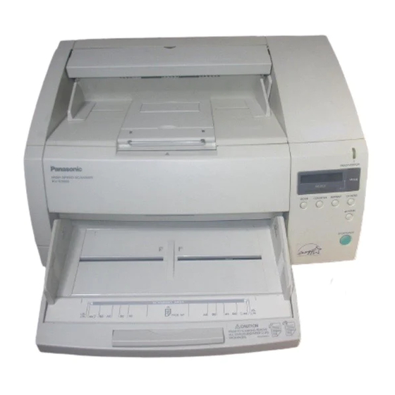
Page 6: Component Identification
KV-S2065L / KV-S2065W 3 COMPONENT IDENTIFICATION... -
Page 7: Installation
KV-S2065L / KV-S2065W 4 INSTALLATION 4.1. Minimum Space Requirements Be sure to maintain the recommended space requirements for proper ventilation. 4.2. Removing and Keeping Screw and Fixture... -
Page 8: Dimm Module Extension
KV-S2065L / KV-S2065W 4.3. DIMM Module Extension A maximum of 256 MB extended memory may be required depending on the combination of the paper size, resolution and gray scale mode. To determine how much extended memory is required, refer to the following page “Additional Memory Size each scanning mode (MB)”. - Page 9 KV-S2065L / KV-S2065W Duplex/4bit, 8bit Size Resolution (dpi) B4 (JIS) B5 (JIS) B6 (JIS) Double Letter Legal Letter Simplex/Binary Size Resolution (dpi) B4 (JIS) B5 (JIS) B6 (JIS) Double Letter Legal Letter Duplex/Binary Size Resolution (dpi) B4 (JIS) B5 (JIS)
-
Page 10: Installing Dimm Module
KV-S2065L / KV-S2065W 4.5. Installing DIMM Module Insert the DIMM module into the connector on the SCSI interface board at an angle [ Place ( 1 ) ]. Push in the module as far as it goes. The levers should lock automatically. If not, push the levers to lock the module in [Place ( 2 ) ]. -
Page 11: Connecting The Unit To A Personal Computer
KV-S2065L / KV-S2065W 4.7. Connecting the Unit to a Personal Computer Note: * AC cord shown on the figure is for AC100-120V. Caution : Set the power switch on the scanner and on the personal computer to OFF before connecting the interface cable. -
Page 12: Lcd Settings
KV-S2065L / KV-S2065W 4.9. LCD Settings Before scanning the document, perform the required settings on the display. Setting information and scanner conditions are shown on the display. 4.9.1. Setting the language Turn the power on while pressing the HOME key. - Page 13 KV-S2065L / KV-S2065W Press the SELECT [ ] Key or [ ] Key to select the desired setting. The [ ] Key moves to the next ID as shown below. The [ ] Key moves to the previous ID. Press the MODE Key [ ] to switch to the terminator setting.
-
Page 14: Sectional Views
KV-S2065L / KV-S2065W 5 SECTIONAL VIEWS 5.1. Image Sensors, Motors and Imprinters (Option) 5.2. Rollers... -
Page 15: Circuit Boards
KV-S2065L / KV-S2065W 5.3. Circuit Boards... -
Page 16: Sensor Boards And Switches
KV-S2065L / KV-S2065W 5.4. Sensor Boards and Switches... -
Page 17: Mechanical Function
KV-S2065L / KV-S2065W 6 MECHANICAL FUNCTION 6.1. Paper Feed Mechanism 1. When PC outputs the scanning-start command, the Hopper lifts until the paper contacts the Paper Feed Roller. 2. The Conveyor Motor is transferred to the rotation of the Conveyor Rollers, Drive Rollers and Exit Roller. -
Page 18: Manual Feed Mechanism And Adf Adjustment
KV-S2065L / KV-S2065W 6.2. Manual Feed Mechanism and ADF Adjustment By setting the ADF/manual feed Selector to the Manual position you can separate the Retard Roller from the Separation Roller and scan one sheet or several sheets. By setting the ADF/manual feed Selector to the ADF ADJ. -
Page 19: Maintenance
KV-S2065L / KV-S2065W 7 MAINTENANCE 7.1. Maintenance Chart C: Clean R: Replace (x1000 sheets) Description Part No. Paper Feed Roller PBDRA0064Z Separation Roller PBDRA0065Z Retard Roller PBDRA0066Z Drive Roller 1 PBDRX01S2065 Drive Roller 2 PBDRX01S2065 Drive Roller 3 PBDRX01S2065 Conveyor Roller 1 -3... -
Page 20: Roller Cleaning
KV-S2065L / KV-S2065W 7.2. Roller Cleaning 7.2.1. Paper Feed Roller, Separation Roller, Retard Roller 1. Turn off the Power. 2. Open the Front door. 3. Clean the surfaces of the Paper Feed Roller and Separation Roller and Separation Roller with cleaning paper (KV-SS03). - Page 21 KV-S2065L / KV-S2065W 7.2.2. Drive Roller and Conveyor Rollers 1. Turn off the Power. 2. Open the Front door. 3. Clean the Driver and Conveyor Rollers with cleaning paper (KV-SS03), as shown in Fig. 7-3 (same as cleaning the Plastic Free...
-
Page 22: Cis Glass, Document Sensors And Double Feed Detection Sensors Cleaning
1. Open the Front door. 2. Clean the CIS glass using the accessory roller cleaning paper (KV-SS03). Also, remove the dirt on the document sensors and double feed detection sensors with the blower Scanner (KV-S2065L/W) has. Note: When cleaning the bottom CIS glass, do not touch the tip of the plastic pointer (black) in the back of the unit. -
Page 23: Sensor Roller Cleaning
KV-S2065L / KV-S2065W 7.4. Sensor Roller Cleaning 1. Open the Front door. 2. Clean the Sensor Roller with cleaning paper (KV-SS03), as shown in Fig. 7-3. Note: If the Sensor Roller is removed while cleaning, re-attach it after cleaning as follows. -
Page 24: Replacing Limited Life Parts
KV-S2065L / KV-S2065W 7.5. Replacing Limited Life Parts If “Warning Replace Roller” message is displayed on the LCD, replace the Paper Feed Roller Module and Retard Roller Module at the same time. 1. Turn the power off and unplug the power cord. - Page 25 KV-S2065L / KV-S2065W 3. Place your finger on the Paper Feed Roller Block Shaft and pull it towards you to remove the Paper Feed Roller Block from the magnet [(1)]. Push down the Green Lock Levers and remove the Paper Feed Roller Module from the scanner by holding the Green Lock Levers [(2)].
- Page 26 KV-S2065L / KV-S2065W 6. Push up on the Paper Feed Roller Block and it will magnetically attach to the chassis. Note: When attaching the Paper Feed Roller Block to the chassis, do not damage the roller. You are now finished attaching the Paper Feed Roller Module.
- Page 27 KV-S2065L / KV-S2065W 8. Pull the right side of the shaft in the direction of the arrow and hold it there [(1)]. Pull the Retard Roller Module in the direction of the arrow [(2)] and then remove it. 9. Take out the Retard Roller Module in the optional “Roller Exchange Kit (KV-SS009)”.
- Page 28 KV-S2065L / KV-S2065W 12. Close the Front Door. Note 1: Push both sides of the Front Door down slowly until it clicks into place. Note 2: After replacing rollers, clear “Replace Roller Warning” on Other Setting Mode as shown in Section 9.
-
Page 29: Disassembly Instructions
KV-S2065L / KV-S2065W 8 DISASSEMBLY INSTRUCTIONS 8.1. Disassembly Flowchart When reassembling, perform the steps in the reverse order unless otherwise noted in Reassembling Notes. -
Page 30: Exterior
KV-S2065L / KV-S2065W 8.2. Exterior 8.2.1. Rear Panel (with Post Imprinter Door) Remove 6 screws. Remove cable from CN530 of POST IMPRINTER DOOR Board. 8.2.2. Side Cover (R) Remove 2 screws and the Side Cover (R). Remove Side Cover (R) pushing down for arrow direction. - Page 31 KV-S2065L / KV-S2065W 8.2.4. Side Panel (R) Remove the Rear Panel. (See 8.2.1) Remove the Side Cover (R). (See 8.2.2) Remove the Switch Panel. (See 8.2.3) Remove the Rear Panel. (See 8.2.1) Remove 4 screws and the Side Panel (R).
- Page 32 KV-S2065L / KV-S2065W 8.2.7. Side Panel (L) Open Front Door. Remove 2 screws and the Side Panel (L). (Pull out while pushing down the 3 locking sections from the chassis) 8.2.8. Feed Unit Cover (L) Remove 2 screws after removing Pre Imprinter Door.
-
Page 33: Unit Components
KV-S2065L / KV-S2065W 8.2.10. Hopper Unit Remove the Switch Panel and the Side Panel (L). (See 8.2.3 and 8.2.7) Remove 4 screws (A). Remove 2 screws (B). Disconnect connector CN512. Note: When assembling, cable connected to CN512 should be inserted, while white base side of the cable (without character) is located to the upper. - Page 34 KV-S2065L / KV-S2065W 8.3.2. CIS (Contact type Image Sensor) Back Remove Sensor Roller 1. Remove screw and Conveyor Plate Lower 2. Remove Drive Roller 3. Remove 4 hexagonal bolts. Disconnect all connectors. Remove the CIS Back. Remove 4 screws on the both sides of CIS Plate.
-
Page 35: Paper Feed Roller
KV-S2065L / KV-S2065W 8.3.5. Retard Roller Open the Front Door and remove Lower Conveyor Plate 1. Remove the Retard Roller, as shown in Fig. 8-16. 8.3.6. Paper Feed Roller Open the Front Door. Pull the Feeder Roller Block from Magnet. - Page 36 KV-S2065L / KV-S2065W 8.3.8. Straight Exit Roller Remove the Rear Panel and the Straight Exit Roller. Remove E-Rings from both sides of roller, and remove bearing and gear. 8.3.9. Drive Belt Remove Side Panel(L). (See 8.2.7) Loosen 2 screws and release the Tension Pulley.
- Page 37 KV-S2065L / KV-S2065W 8.3.11. Feed Motor Remove Drive Roller-1. (See 8.3.4-(1), (2), (3)) Remove the screw (A) from the Retard Transmission Shaft Holder. Note: When reattach a rink spacer to the scanner, be careful with the direction of the spacer.
- Page 38 KV-S2065L / KV-S2065W 8.3.13. Straight Exit Conveyor Plate Remove Rear Panel. (See 8.2.1) Remove Straight Exit Roller. (See 8.3.8) Remove 3 screws. Remove the Straight Exit Conveyor Plate. 8.3.14. Board Box Cover Remove Side Cover (R). (See 8.2.2) Remove 5 screws and the Board Box Cover.
- Page 39 KV-S2065L / KV-S2065W 8.3.16. Board Box Unit Remove Rear Panel, Side Cover (R), Switch Panel, and Side Panel (R). (See 8.2.1 to 8.2.4) Remove 8 screws and wire harness. Remove 2 screws (Back View). Remove the Board Box Unit. 8.3.17. Front Door Switch Remove Board Box Unit.
-
Page 40: Circuit Board Assemblies
KV-S2065L / KV-S2065W 8.3.18. Gas Spring Remove Board Box Unit. (See 8.3.16) Remove the screw(a). Remove the screw(b). Remove the Gas Spring. 8.3.19. Pointer Remove Board Box Unit. (See 8.3.16) Remove the right side E-Ring. Remove the left side Paper Path Selector and E-Ring. - Page 41 KV-S2065L / KV-S2065W 8.4.2. POWER Board Remove Board Box Unit. (See 8.3.16) Remove 2 screws and separate the Power box from the Board Box Unit. Disconnect all connect tors from/to POWER Board. Note: See SECTION 11 BLOCK DIAGRAM for connections Remove 10 screws and the POWER Board.
-
Page 42: Drive Board
KV-S2065L / KV-S2065W 8.4.4. DRIVE Board Remove Rear Panel. (See 8.2.1) Disconnect 5 connectors (CN371, CN372, CN341, CN351, CN332) from/to DRIVE Board. Note: See SECTION 11 BLOCK DIAGRAM for connections. Remove 2 screws(a). Pull the DRIVE Board. Disconnect connector (CN331) from/to DRIVE Board Remove 3 screws(b). - Page 43 KV-S2065L / KV-S2065W 8.4.6. PANEL Board Remove Switch Panel. (See 8.2.3) Disconnect the CN551. Remove 6 screws. 8.4.7. DC-DC CONVERTER Board Remove Side Cover (R), and Switch Panel. (See 8.2.1 and 8.2.3) Remove 4 screws. Disconnect CN861 and CN862. 8.4.8.
- Page 44 KV-S2065L / KV-S2065W 8.4.9. RELAY (UPPER) Board Remove Exit Cover and Pre Imprinter Door. (See 8.2.5 and 8.2.6) Remove 3 screws (A). Remove 2 screws (B). Disconnect all connectors. 8.4.10. WAITING SENSOR Board Remove the Conveyor Plate Upper 2. (See 8.3.1(1)-(3)) Remove 2 screws.
- Page 45 KV-S2065L / KV-S2065W 8.4.12. WAITING LED Board Remove Drive Roller 1. (See 8.3.4) Remove 2 screws. Disconnect CN522. 8.4.13. STARTING POSITION LED Board Remove Drive Roller 2. Remove 2 screws. Disconnect CN519 and CN520. 8.4.14. RELAY (LOWER) Board Remove Drive Roller 2. (See 8.3.4) Disconnect all connectors.
- Page 46 KV-S2065L / KV-S2065W 8.4.15. PAPER JAM SENSOR Board Remove Turn Conveyor Plate. (See 8.3.12) Remove the PAPER JAM SENSOR Board. Disconnect CN526 and CN527 inside Turn Conveyor Plate. 8.4.16. ENDING (FRONT) POSITION LED Board Remove Turn Conveyor Plate. (See 8.3.12) Remove the ENDING (FRONT) POSITION LED Board.
- Page 47 KV-S2065L / KV-S2065W 8.4.18. HOPPER POSITION Board Remove Lower Cover Plate 1. (See 8.3.5-(1)) Remove Conveyor Plate Lower 2. (See 8.3.2-(2)) Remove Hopper Unit. (See 8.2.10) Push 3 Clip and remove 1 screw as shown in the Fig. 8-49 and remove the HOPPER POSITION Board.
-
Page 48: Power Switch
KV-S2065L / KV-S2065W 8.4.21. POINTER DETECTOR Board Remove Conveyor Roller. (See 8.3.3) Remove 2 screws. Disconnect CN514 and CN515. 8.4.22. Power Switch Remove the Power Box. (See 8.4.2-(1), (2)) Disconnect the 2 lead terminals from the Power Switch terminal. Remove the Power Switch from the chassis. (Pull out while... -
Page 49: Operation
KV-S2065L / KV-S2065W 9 OPERATION 9.1. Front Panel Specifications Item Contents Indication Device LCD Display Indication Matrix 16 Characters x 2 lines Kind of Character for Indication Alphabet, Number, Square Phonetic, Japanese Syllabary Indicated Contents System Status ( Initializing, Ready, Scanning, Error, Warning ) -
Page 50: Operation - 1 ( Normal Mode )
KV-S2065L / KV-S2065W Note: Setting the language Turn the power on while pressing the HOME Key. Use the “ ”Key or the “ ” Key to select “English Letter”, “English A4” or “Deutsch A4”, “ A4”. Press the HOME Key. -
Page 51: Operation - 2 (Service Mode)
KV-S2065L / KV-S2065W 9.3. Operation - 2 (Service Mode) To enter Service Mode, turn on the Scanner while pressing the SCAN and the OTHER Keys simultaneously. Service Mode includes the Service Setting Mode and Test Mode. The Service Setting Mode offers functions that are not available in Normal Mode. The Service Setting Mode has “Set Warning value”... -
Page 52: Setting List
KV-S2065L / KV-S2065W 9.4. Setting List 9.4.1. Scan Setting Mode ( Normal Mode 1 ) Factory Item Setting Contents Default Setting F.Color drop Host Green Host Host Host Host F.Brightness Host Norm Host Host F.Emphasis Host Smooth None Medium High... - Page 53 KV-S2065L / KV-S2065W 9.4.3. Imprinter Setting Mode ( Normal Mode 3 ) Factory Item Setting Contents Default Setting Pre Imprint (Select Host Count Host Host contents to print) Pre Position (Set 0 - 72 Host Host Host printed position) 3 Pre Font...
- Page 54 KV-S2065L / KV-S2065W 9.4.5. Service Setting Mode ( Service Mode 1 ) Factory Item Setting Contents Default Setting 1 PCB Rev.No. (Disp. PCB Version and others) 5000 2 Clean Roller (Set counter for roller cleaning timing) 50000 50000 - 10000...
- Page 55 KV-S2065L / KV-S2065W 9.4.6. Test Mode ( Service Mode 2 ) Factory Item Setting Contents Default Setting 1-a Feed Test (Set Resolution and Test ) 100 - 600 START 1-b Feed Test (Set Size and Test) START 1-c Feed Test (Set Length Control and Test)
-
Page 56: Setting Operation ( Normal Mode )
KV-S2065L / KV-S2065W 9.5. Setting Operation ( Normal Mode ) START POWER ON READY on LCD? Push SCAN key once Push COUNTER key once Push IMPRINT key once Push OTHERS key once Enters Enters Enters Enters Scan Counter Imprint Other... - Page 57 KV-S2065L / KV-S2065W 9.5.1. Scan Setting Mode ( Normal Mode 1 ) 9.5.1.1. Mode - 1 (From Section 9.5) Item (From Section 9.5.2) F. Color drop F. Brightness F. Emphasis F. Contrast F. Halftone Select a menu of Setting Item by pushing B.
- Page 58 KV-S2065L / KV-S2065W 9.5.1.2. Mode - 2 (From Section 9.5) Item (18)-a (18)-a Save Setting (Select memory) Push “ ” or “ ” key until Select a menu of Setting Item by 18. Save Setting pushing “ ” or “...
- Page 59 KV-S2065L / KV-S2065W 9.5.2. Counter Setting Mode ( Normal Mode 2 ) (From Section 9.5) Item (1) Disp. Counter (2) User Counter Set counter value Select a menu of Setting Item by Set increment value pushing “ ” or “...
- Page 60 KV-S2065L / KV-S2065W 9.5.3. Imprinter Setting Mode ( Normal Mode 3 : Option ) 9.5.4. Other Setting Mode ( Normal Mode 4 ) 9.5.4.1. Mode - 1 (From Section 9.5) Item (1) Version (2) Buzzer (3) SCSI ID (1) Version indication Select a menu of Setting Item by M;...
-
Page 61: Setting Operation ( Service Mode )
KV-S2065L / KV-S2065W 9.5.4.2. Mode - 2 (From Section 9.5) Item (6) Clean Roller Dips. % Clear warning for (6)- ; Indicates % based on the value of Select a menu of Setting Item by "Clean Roller" “ Clean Roller ” in Service Mode Setting (7) Replace Roller pushing “... - Page 62 KV-S2065L / KV-S2065W 9.6.1. Service Setting Mode ( Service Mode 1 ) 9.6.1.1. Mode - 1 (From Section 9.6) (1) PCB Rev. No. (Disp. PCB Version and others) PCB Rev. No. Select a menu of Setting Item by MaOGsOIfOOGiOMeO pushing “...
- Page 63 KV-S2065L / KV-S2065W 9.6.1.3. Mode - 3 (From Section 9.6) (11) Set Default Select a menu of Setting Item by pushing key. “ ” “ ” Set Default? Pushing keys changes setting “ ” “ ” Push keys “ ”...
- Page 64 KV-S2065L / KV-S2065W 9.6.2. Test Mode ( Service Mode 2 ) 9.6.2.1. Mode - 1...
- Page 65 KV-S2065L / KV-S2065W...
- Page 66 KV-S2065L / KV-S2065W 9.6.2.2. Mode - 2 (From Section 9.6) (2) F. CIS LED / B. CIS LED (3) F. CIS Black Level / B. CIS Black Level (15) Double Feed (Check double feed sensitivity after setting input-level) Select a menu of Setting Item by “...
- Page 67 KV-S2065L / KV-S2065W 9.6.2.3. Mode - 3 (4) Document Sensor (From Section 9.6) (Check each document sensor condition) (5) Sensor Sensitive Level (6) Door & Home Sensor (12) Memory Test (13) Sleep Mode Select Sensor Test ((4) or (5) or (6) or (11) or (12)) Select a menu of Setting Item by pushing “...
- Page 68 KV-S2065L / KV-S2065W 9.6.2.4. Mode - 4 9.6.2.5. Mode - 5 (From Section 9.6) (16) Adjust Double Feed Detector (17) Adjust Length Automatically Select a menu of Setting Item by (18) Adjust Front V. position pushing “ ” or “...
- Page 69 KV-S2065L / KV-S2065W 9.6.2.6. Mode - 6 (From Section 9.6) (14) Init. EEPROM This test is used only in case EEPROM has some errors * Please be very careful as this test Select a menu of Setting Item by operation initializes all data pushing “...
-
Page 70: Error Code
KV-S2065L / KV-S2065W 9.7. Error Code Error Code Classified ST1 ST2 ST3 ST4 Content Code 00 No Paper Error 00 Paper Feed Jam (when paper does not reach Waiting Sensor): ST2 shows the rest numbers (approx.) of paper. 00 Jam 1 (when paper does not reach Starting Position Sensor): ST2 shows the rest numbers (approx.) of paper. - Page 71 KV-S2065L / KV-S2065W Classified ST1 ST2 ST3 ST4 Content Code 00 Front-side Lamp Lighting Error (STS2: Lighting Value, STS3: AD input value) 00 Back-side Lamp Lighting Error (STS2: Lighting Value, STS3: AD input value) 00 Scanning Position Adjustment (Auto Mode) Error...
-
Page 72: Troubleshooting
KV-S2065L / KV-S2065W 10 TROUBLESHOOTING Error Codes are listed in section 9.7 “Error Code”. Test the check points in order from the first entry. Error Code Possible Cause Check Point Program ROM Error on MAIN CONTROL Board Replace the Program ROM... - Page 73 KV-S2065L / KV-S2065W Error Code Possible Cause Check Point Skew ( R ) Sensor Error Remove any dust on the LED on the WAITING LED Board, or on the light receptor on the WAITING SENSOR Board Check that the LED on the WAITING LED Board, the light...
- Page 74 KV-S2065L / KV-S2065W Error Code Possible Cause Check Point Ending ( Rear ) Position Sensor Error Remove any dust on the LED on the ENDING (REAR) LED Board, or on the light receptor on the ENDING (REAR) POSITION SENSOR Board...
- Page 75 KV-S2065L / KV-S2065W Note: If neither LCD indication nor memory accessed from CPU work properly when initializing, LED6 to LED1 ( D106 - D101 ) status can be available for troubleshooting. Scanner CPU checks attached ROM and RAM on main control and on SCSI I/F board after power ON. It displays 6 red LED patterns on main board according to progress of checking.
- Page 76 KV-S2065L / KV-S2065W...
-
Page 77: Block Diagram
KV-S2065L / KV-S2065W 11 BLOCK DIAGRAM... - Page 78 KV-S2065L / KV-S2065W...
-
Page 79: Explanation Of Connector
KV-S2065L / KV-S2065W 12 EXPLANATION of CONNECTOR CN1000 (MAIN) - (CIS [FRONT]) Pin No. Signal Name Description Pin No. Signal Name Description CIS IN1 Contact Image Sensor Signal1 Ground AGND Analog Ground CCD(RST) Not Used CCD(P2) Not Used CCD(P1) Not Used... - Page 80 KV-S2065L / KV-S2065W CN1006 (MAIN) - CN2001(MOTHER)(continued) Pin No. Signal Name Description Pin No. Signal Name Description Ground Chip Select for Door Sensor Ground Chip Select for Key Chip Select for Key Chip Select for Size Sensor CN600(SCSI) Ground Pin No.
- Page 81 KV-S2065L / KV-S2065W CN601(SCSI) (continued) Pin No. Signal Name Description Pin No. Signal Name Description Ground Ground Ground Ground Ground CPUA8 CPU Adress Ground CPUA7 CPU Adress N.C. N.C. CPUA6 CPU Adress N.C. N.C. CPUA5 CPU Adress N.C. N.C. CPUA4...
- Page 82 KV-S2065L / KV-S2065W CN2003(MOTHER) - CN331(DRIVE) Pin No. Signal Name Description Pin No. Signal Name Description SKEW Sensor Comparater Level Ground DACDI DAC Data PREDOOR Pre Imprinter Door Sensor input DACCLK DAC Clock +5VS DACLD DAC Load Ground +5VS +38V...
- Page 83 KV-S2065L / KV-S2065W CN2008(MOTHER) - Post Imprinter(continued) Pin No. Signal Name Description Pin No. Signal Name Description +38V +38V SIZE2 Paper Size Sensor2 +12VS +12V Ground SIZE1 Paper Size Sensor1 Ground LEVER Retard Position Sensor CN2009(MOTHER) - CN862(DC-DC CONVERTER) Paper Detector Pin No.
- Page 84 KV-S2065L / KV-S2065W CN515(POINTER DETECTOR) - CN516(ENDING[REAR]) Pin No. Signal Name Description Pin No. Signal Name Description Ground Conveyor Motor Phase-A Conveyor Motor Phase-B(-) EXIT R Ending (Rear) Position Sensor CCOMB +24V for Conveyor Motor JAM LED Paper JAM LED Output Conveyor Motor Phase-B N.C.
-
Page 85: Circuit Boards
KV-S2065L / KV-S2065W 13 CIRCUIT BOARDS 13.1. MAIN CONTROL Board (Component Side) -
Page 86: Main Control Board (Solder Side)
KV-S2065L / KV-S2065W 13.2. MAIN CONTROL Board (Solder Side) -
Page 87: Scsi Board (Component Side)
KV-S2065L / KV-S2065W 13.3. SCSI Board (Component Side) -
Page 88: Scsi Board (Solder Side)
KV-S2065L / KV-S2065W 13.4. SCSI Board (Solder Side) -
Page 89: Mother Board
KV-S2065L / KV-S2065W 13.5. MOTHER Board (Component Side) (Solder Side) -
Page 90: Drive Board (Component Side)
KV-S2065L / KV-S2065W 13.6. DRIVE Board (Component Side) -
Page 91: Drive Board (Solder Side)
KV-S2065L / KV-S2065W 13.7. DRIVE Board (Solder Side) -
Page 92: Panel Board
KV-S2065L / KV-S2065W 13.8. PANEL Board 13.9. RELAY (LOWER) Board... -
Page 93: Relay (Upper) Board
KV-S2065L / KV-S2065W 13.10. RELAY (UPPER) Board 13.11. HOPPER POSITION Board 13.12. SIZE DETECTOR Board... -
Page 94: Waiting (Led) Board
KV-S2065L / KV-S2065W 13.13. WAITING (LED) Board 13.14. POINTER Board 13.15. ENDING (REAR) SENSOR Board 13.16. PAPER JAM (LED) Board 13.17. START POSITION (LED) Board... -
Page 95: Ending (Rear) Led Board
KV-S2065L / KV-S2065W 13.18. ENDING (REAR) LED Board 13.19. STARTNG POSITION SENSOR Board 13.20. WAITING SENSOR Board 13.21. ENDING (FRONT) SENSOR Board 13.22. PAPER JAM SENSOR Board... -
Page 96: Ending (Front) Led Board
KV-S2065L / KV-S2065W 13.23. ENDING (FRONT) LED Board 13.24. POST IMPRINTER DOOR Board 13.25. DC-DC CONVERTER Board... -
Page 97: Power Board
KV-S2065L / KV-S2065W 13.26. POWER Board... -
Page 98: Schematic Diagram
KV-S2065L / KV-S2065W 14 SCHEMATIC DIAGRAM Index 14.1 MAIN CONTROL Board 14.2 SCSI Board 14.3 MOTHER Board 14.4 DRIVE Board 14.5 PANEL Board 14.6 RELAY LOWER and UPPER Boards 14.7 Sensor Boards 14.8 DC-DC CONVERTER and POWER Board Note: This Schematic Diagram is the latest at the time of printing and subject to change without notice. -
Page 99: Main Control Board
KV-S2065L / KV-S2065W 14.1. MAIN CONTROL Board R1002 +5VA L1002 AGND ADF[0-9] 002:2E AGND 006:5C CCDINE Q1001 IC1003 2SA1037K-T146 AGND R1034 AGND 002:1D ADCLKF1 AGND Z1008 002:1D ADOEF1 ADF[7] R1035 ADF[6] AVDD ADF[5] AVSS DVDD ADF[4] VTOP AGND DVSS VREFP... - Page 100 KV-S2065L / KV-S2065W Z1025 Z1026 Z1027 Z1028 Z1030 Z1031 Z1033 SHDFA[0-13] 003:1A SHDFA[0-13] SHDFD[0-7] 003:2B SHDFD[0-7] SHDBD[0-7] 003:2D SHDBD[0-7] 003:1A SHDFWR 003:1A SHDFOE R1153 +3V_GA5 +3V_GA6 CPUD[0-15] R1154 Z1110 Z1109 004:9A;005:6C;006:8E +3V_GA1 CPUA[0-23] 004:9E;005:1A;006:8E RESET 004:9A;005:1B;006:8D CPUHWR 004:9A;005:1A;006:8D +3V_GA3 CPURD 004:9A;005:1A;006:8D...
- Page 101 KV-S2065L / KV-S2065W 002:1A SHDFOE 002:9D LBFWR 002:1A SHDFWR 002:9C LBFOE 002:1A SHDFA[0-13] 002:9C LBFA[1-15] IC1012 IC1008 IC1010 1 A14 LBFA[15] 1 A14 LBFA[15] 1 A14 SHDFA[12] 2 A12 LBFA[13] 2 A12 LBFA[13] 2 A12 SHDFA[7] 3 A7 LBFA[14] LBFA[8]...
- Page 102 KV-S2065L / KV-S2065W R1116 LEASCOUNT 006:8C 006:8B IMGWAIT Q1019 UN2212-(TX) Z1055 Z1056 100K RESET 002:9A;005:1B;006:8D CPULWR 005:1A CPUHWR CPUHWR 002:9A;005:1A;006:8D IC1015 CPURD 002:9A;005:1A;006:8D SN74HC245NS-EL20 CPUAS 006:8D 1 2 3 4 1 2 3 4 CPUD[0-15] 002:9A;005:6C;006:8E CPUD[8] CPUD[9] 001:4E SIZEF0...
- Page 103 KV-S2065L / KV-S2065W 002:9A;004:9A;006:8D CPUHWR 004:9A CPULWR CPURD 002:9A;004:9A;006:8D CPUA[0-23] 002:9A;004:9E;006:8E RESET 002:9A;004:9A;006:8D IC1027 IC1028 FLASH-ROM FLASH-ROM CPUA[20] CPUA[20] CPUA[19] CPUA[19] CPUA[18] CPUA[18] IC1029 IC1030 CPUA[17] CPUA[17] CPUA[16] SRAM CPUA[16] SRAM RY/BY RY/BY CPUA[15] CPUD[7] CPUA[15] CPUD[15] CPUA[15] CPUA[15] CPUD[6]...
- Page 104 KV-S2065L / KV-S2065W D1008 MA132A-(TX) IC1033 AMP- F/BOCL- AMPOUT OCL+ IC1035 D1014 8 VCC VREF 7 DISCH TRIG 3.3V/5V 6 THRES TIMERIRQ 004:1E 5 CONT RESET VBOOT TIMER L1021 N.M. R1134 VOUT N.M. VOUT 0.5W VOUT R1135 VOUT 18 VDD 0.5W...
-
Page 105: Scsi Board
KV-S2065L / KV-S2065W 14.2. SCSI Board SCSIREQ SCSIREQ 4:7F;7:1B R616 IRQSCSI 5:4E Q602 N.M. SYSRST 5:8B SYSRST R778 DB[0-7] 100K 5:8B;7:1D CPWR 7:3E SCSIRD CN600 CN601 5:8D;7:1C CSSCSI 5:8C TERMPC DB[0] DB[1] DB[2] DB[3] DB[4] DB[7] DB[5] DB[6] DB[7] DB[6]... - Page 106 KV-S2065L / KV-S2065W 3:9E MCLK3 MCLK1 3:9E MCLK1 MRAS1 4:8A MCAS1 4:8A MCAS0 MAB[0-14] MAB[0-14] 4:8A MAB[0-14] MDQ[0-63] MDQ[0-63] MDQ[0-63] 4:8B MDQMB[0-7] MDQMB[0-7] MDQMB[0-7] MDQMB[0-7] MDQMB[0-7] 4:8B MDQMB[0-7] MAA[13-14] 4:8A MAA[13-14] MAA[0-11] CN605 MAA[0-11] 4:8A 390195-6 4:8B 1 VSS MDQ[0]...
- Page 107 KV-S2065L / KV-S2065W MSD[0-7] MSD[0-7] 4:8A R643 5:4E CLK27M N.M. MSA[0-13] 4:8A MSA[0-13] IC607 R644 1 ST IC618 2 GND OSCIN REFOUT R648 OSCOUT OVDD AVDD OVSS SG-8002JF2697MSCC 4:3F MSOE 26.97MHz STOP R719 FOUT VCLK 4:1E 4:3F MSWE AVSS DVSS...
- Page 108 KV-S2065L / KV-S2065W MSD[0-7] MSD[0-7] 3:9A 3.3V MSA[0-13] 3:1B MAA[0-11] MAA[0-11] 2:1B L620 MAA[13-14] +3V_G1 MAA[13-14] 2:1A L624 R675 Z626 L621 MDQMB[0] MDQMB[1] L625 MDQMB[4] MDQMB[5] L622 MCAS0 MCAS0 2:1A MRAS0 L626 MRAS0 2:1C MWE0 MWE0 2:1E 2:1C L623 +3V_G1...
- Page 109 KV-S2065L / KV-S2065W 3.3V CPD[8-15] CPD[8-15] 7:3D C798 C803 C806 CN602 CPA[0-8] 1:1C;4:2E N.M. N.M. N.M. RESET Z657 4:2E SYSRST CPUAS 4:2F;7:1E CPAS CPUHWR 1:1A;7:1D CPWR CPURD CPRD 7:1D Z658 IC615 CPUD[15] CPD[15] CPUD[14] CPD[14] (VCC=2~6V) CPUD[13] CPD[13] CPUD[12] CPD[12]...
- Page 110 KV-S2065L / KV-S2065W SMDD[0-15] SMD[0-15] 4:8E SMDD[0-15] 1:1E SMD[0] R750 SMDD[0] SMD[1] N.M. R751 SMDD[1] SMD[2] R752 N.M. SMDD[2] N.M. R753 SMDD[3] SMD[3] SMD[4] R754 N.M. SMDD[4] SMD[5] N.M. R755 SMDD[5] SMD[6] R756 N.M. SMDD[6] SMD[7] N.M. R757 SMDD[7] N.M.
-
Page 111: Mother Board
KV-S2065L / KV-S2065W 14.3. MOTHER Board 001:1D;001:9E [PREIMPRINTER] +5VSCUT [POSTIMPRINTER] 2SJ462-T2 +12VS 001:1D +12VS RESETIMP 001:9E 001:9C +5VSCUT +38V R2993 +24VD +38V 001:1D;001:9E [MAIN 1/2] 0.5W Q2999 +5VS 2.2K CN2007 CN2008 POWERCNT CTS0 -5VA +5VA Q2998 CTS0 TXD0 CTS1 TXD0... - Page 112 KV-S2065L / KV-S2065W...
-
Page 113: Drive Board
KV-S2065L / KV-S2065W 14.4. DRIVE Board +24V3 LD[0-7] CN331 LD[0] [CONVEYOR] CSFEED Q342 CN341 CSCARR IC391 DTB113ZSTP IC341 SKEWLEVEL TC74HC273P SLA7044MLF872 C392 C342 DACDATA CCOMA DACCLK IC371 1 CLR 1 OUTA OUTB DACLD 2 1Q 2 STROBEA DATAB CCOMB +38V... - Page 114 KV-S2065L / KV-S2065W...
-
Page 115: Panel Board
KV-S2065L / KV-S2065W 14.5. PANEL Board LCD UNIT Z559 CN551 IC551 3 4 5 R581 1.8K +12V Z555 Z551 Z552 Z554 Z553 3 4 5 3 4 5 3 4 5 3 4 5 3 4 5 BUZZER RCM7065X-B KEY1... - Page 116 KV-S2065L / KV-S2065W...
-
Page 117: Relay Lower And Upper Boards
KV-S2065L / KV-S2065W 14.6. RELAY LOWER and UPPER Boards CN502 POINTER EXIT(REAR) JAM(LED) Q501 IC501 2SC3311A-(TA) N.C. SGND Q502 S7B-PH-K-S 2SC3311A-(TA) VrefL CN501 Q503 SGND 2SC3311A-(TA) HOPPER POS. SIZE1 +12V VrefU LEVER +12V SGND SGND D509 SGND MA165-(TA5) M62353P SIZE2... - Page 118 KV-S2065L / KV-S2065W CN507 AN3(EXIT FRONT) SGND IL-S-6P-S2T2-EF IC504 SGND TLP832 [PREIMPRINTER DOOR] Q507 2SC3311A-(TA) R536 CN508 SGND SGND EXIT FRONT(LED)(DAC7) AN5(JAM) Q508 2SC3311A-(TA) SGND IL-S-5P-S2T2-EF +24V R530 SGND +24V Q514 CN506 2SC3311A-(TA) Q510 R534 CLK40K 2SC3311A-(TA) USOUND LEVEL(DACB) C518...
-
Page 119: Sensor Boards
KV-S2065L / KV-S2065W 14.7. SENSOR Boards DOUBLE FEED DETECTOR(GENERATOR)STANBY,SKEW STARTING POSITION X502 MA40S4S GENERATOR Q533 Q531 Q529 Q527 [SKEWL] [STANBY] [SKEWR] 2SC3311A-(TA) 2SC3311A-(TA) 2SC3311A-(TA) 2SC3311A-(TA) CN524 CN523 CN525 Q534 Q532 Q530 Q528 PN168 PN168 PN168 PN168 TO RELAY2 (PBAPA0269-CN509) IL-S-7P-S2L2-EF... - Page 120 KV-S2065L / KV-S2065W HOPPER POSITION DETECTOR PAPER, PAPER SIZE SENSOR FLEXIBLE TO RELAY1 CABLE CN513 CN512 (PBAPA0268-CN504) CN511 IC507 IC508 IC509 IC510 IC511 IC512 TLP832 TLP832 TLP832 TLP832 TLP832 N.M. SIZE5 [SIZE1] [SIZE2] [SIZE3] [SIZE4] [SIZE5] [DOC] SIZE4 SIZE3 Q523...
-
Page 121: Dc-Dc Converter And Power Board
KV-S2065L / KV-S2065W 14.8. DC-DC CONVERTER and POWER Board CN861 CN862 +24V VCC(24V) +24V VCC(24V) +24V +24V VCC(24V) +5Vovp +5VA 3.3Vovp -5VA -5Vovp STBY 3.3Vovp RD7.5ES-T1AB3 B11B-XASK-1 B12B-XASK-1 MA165-(TA5) R869 R866 R863 0.56 IC866 0.56 IC863 0.5W 0.5W NJM79M05FA RCH895-151K... - Page 122 KV-S2065L / KV-S2065W CN801 F801 TH801 LIVE NEUTRAL 250V AB4X2X4.5W L822 B2P3-VH L801 L802 D801 T801 HK-14S080-4010T D3SBA60-4101 CN802 L821 Q821 F802 250V VCC(24V) VCC(24V) 2SJ334 +24V +24V R838 2.2K R804 C809 +5Vovp SRW3333ED-609V017 C834 R834 3.3Vovp -5Vovp 0.047 L803...
-
Page 123: Parts Location And Mechanical Parts List
KV-S2065L / KV-S2065W 15 PARTS LOCATION AND MECHANICAL PARTS LIST Note: RTL (Retention Time Limited) The marking (RTL) in the Remark column indicates that the Retention Time is limited for this item. After the discontinuation of this assembly in production, the item will continue to be available for a specific period of time. The retention period of availability is dependent on the type of assembly, and in accordance with the laws governing part and product retention After the end of this period, the assembly will no longer be available. -
Page 124: Exterior
KV-S2065L / KV-S2065W 15.1. Exterior... - Page 125 Hopper Base (ISO Code:ABS) PJHRB0006Z-J Hopper Plate (For KV-S2065L) (ISO Code:ABS) PJHRB006Z-J1 Hopper Plate (For KV-S2065W) (ISO Code:ABS) PBHRA0194Z-J Paper Guide (R) (For KV-S2065L) (ISO Code:ABS) PBHRA194Z-J1 Paper Guide (R) (For KV-S2065W) (ISO Code:ABS) PBHRA0193Z-J Paper Guide (L) (For KV-S2065L) (ISO Code:ABS) PBHRA193Z-J1...
-
Page 126: Power Unit And Circuit Board
KV-S2065L / KV-S2065W 15.2. Power Unit and Circuit Board... - Page 127 KV-S2065L / KV-S2065W REPLACEMENT MECHANICAL PARTS LIST (Power Unit and Circuit Board) Ref. No. Part No. Part Name & Description Remarks PBJEA0090Z PBAPX012065A POWER Board (RTL) PJJRB0615Z AC Inlet Cable PJJRB0608Z Power Unit Relay Cable (CN861-CN802) PBMCX0086Y Power Box Assembly...
- Page 128 KV-S2065L / KV-S2065W...
-
Page 129: Chassis And Base
KV-S2065L / KV-S2065W 15.3. Chassis and Base 1... - Page 130 Reinforcement Plate (U) 3 PBULA0135Y Reinforcement Plate (U) 4 PBUL30Z Lock Release Plate PBUSA0038Z Conveyor Spring PBHEA0107Z Sub Sheet for KV-S2065L (ISO Code:PVC) PBDRA0112Y-J Sensor Roller for KV-S2065L PBDRA0101X-J Sensor Roller for KV-S2066W PBDRA0073Z Platen Pitch Roller (ISO Code:POM) PBDJA0014Z...
-
Page 131: Chassis And Base 2
KV-S2065L / KV-S2065W 15.4. Chassis and Base 2... - Page 132 GS0203042D Damper PBDFA0094Z Pointer Shaft PBHMA0106Z Gas Spring Collar PBUSA0035Y-J Roller Shaft Assembly PBHEA0107Z Sub Sheet KV-S2065L only (ISO Code:PVC) PBDRA0029Z Free Roller (ISO Code:POM) PBMDA0455Z Gas Spring Fitting Plate PBHMA0133Z Pointer Change Plate PBDSA0099Z Platen Hold Spring (R) PBHRA0117Z...
- Page 133 KV-S2065L / KV-S2065W Ref. No. Part No. Part Name & Description Remarks VJF0036 Rivet K-103G Clamper PBMDA0533Z Plate Clamper CS-2 Clip TMM6463 Clamper MWSP6-22-J Spacer PBHEA0173Z Sheet PJMDB0010Z DRIVE Board Fitting Plate PBAPX042065A DRIVE Board (RTL) PBJEA0549Z Cable (CN2006-CN501) PBJEA0553Y...
- Page 134 KV-S2065L / KV-S2065W...
-
Page 135: Packing
KV-S2065L / KV-S2065W 15.5. Packing... -
Page 136: Tool
KV-S2065L / KV-S2065W 15.6. Tool REPLACEMENT MECHANICAL PARTS LIST (Packing) Ref. No. Part No. Part Name & Description Remarks PJPGB0004Z-L Outer Carton for S2065L PJPGB0004Z-W Outer Carton for S2065W HP-601W2 Joint (ISO Code:PP) PBPGA0322Y Carton PJQXB0001Z Installation Manual/Driver Software PJQMB0021Z... -
Page 137: Electrical Replacement Parts List
KV-S2065L / KV-S2065W 16 ELECTRICAL REPLACEMENT PARTS LIST Note: RTL (Retention Time Limited) The marking (RTL) in the Remark column indicates that the Retention Time is limited for this item. After the discontinuation of this assembly in production, the item will continue to be available for a specific period of time. The retention period of availability is dependent on the type of assembly, and in accordance with the laws governing part and product retention After the end of this period, the assembly will no longer be available. -
Page 138: Main Control Board
KV-S2065L / KV-S2065W 16.1. MAIN CONTROL Board Ref. No. Part No. Part Name & Description RESISTORS R1000/1001 ERJ6GEYJ470 47 / J / 0.125W R1002/1003 ERJ3GEYJ100 10 / J / 0.1W R1004/1005 ERJ6GEYJ181 180 / J / 0.125W R1006-1009 ERJ3GEYJ102 1k / J / 0.1W... - Page 139 KV-S2065L / KV-S2065W Ref. No. Part No. Part Name & Description CAPACITORS C1000 ECUX1E104ZFV 0.1 / Z / 25V C1001 ECEV1AA221 220 / 25V C1002/1003 ECUX1E104ZFV 0.1 / Z / 25V C1005/1006 ECUX1E104ZFV 0.1 / Z / 25V C1008-1010 ECUX1E104ZFV 0.1 / Z / 25V...
- Page 140 KV-S2065L / KV-S2065W Ref. No. Part No. Part Name & Description C1180 ECUX1H220JCV 22P / J / 50V C1181/1182 ECUX1H103KBV 0.01 / K / 50V C1183 ECUX1H220JCV 22P / J / 50V C1184 ECUX1E104ZFV 0.1 / Z / 25V C1185...
- Page 141 KV-S2065L / KV-S2065W Ref. No. Part No. Part Name & Description Q1014 2SC2412K Transistor Q1015-1017 UN2212 Transistor Q1019-1021 UN2212 Transistor IC1000 HD74HCT245FP IC1001 SN74HC4066NS IC1002-1005 AK5482 IC1006 SLA566THF0T IC (Gate Array) IC1007 SG8002JA2697 IC1008-1013 CY7C199-15VC IC (SRAM 256K) IC1014 S-93C66ADFJ...
-
Page 142: Scsi Board
KV-S2065L / KV-S2065W 16.2. SCSI Board Ref. No. Part No. Part Name & Description RESISTORS R601/603 ERJ3GEY0R00 0-ohm Jumper R604 ERJ3GEYJ560 56 / J / 0.1W R606 ERJ3GEY0R00 0-ohm Jumper R607 ERJ3GEYJ472 4.7k / J / 0.1W R608/609 ERJ3GEY0R00 0-ohm Jumper... - Page 143 KV-S2065L / KV-S2065W Ref. No. Part No. Part Name & Description C617 ECEV1AA101SP 100 / 10V C618-620 ECUX1H101JCV 100P / J / 50V C621/622 ECEV1AA101SP 100 / 10V C623/624 ECUX1E104ZFV 0.1 / Z / 25V C625/626 ECUX1H101JCV 100P / J / 50V...
- Page 144 KV-S2065L / KV-S2065W Ref. No. Part No. Part Name & Description C757-759 ECUX1H101JCV 100P / J / 50V C760-762 ECUX1E104ZFV 0.1 / Z / 25V C763 ECUX1H102KBV 1000P / K / 50V C764 ECUX1H331JCV 330P / J / 50V C765...
- Page 145 KV-S2065L / KV-S2065W Ref. No. Part No. Part Name & Description IC609 PI6C2509-133 IC610 SN74HC245NS2 IC611 SN74LV00ANS2 IC612 SN74LV04ANS2 IC613 SN74LV32ANS2 IC614 SLA581THF0M IC(Gate Array) IC615/616 TC7S04FU IC617 SM560BZD IC619/620 HD74HCT245FP IC621 SN74LV573ANS IC622 HD74LV245AFP IC623 SN74LV02ANS2 OTHERS CN600/601 FCN235D050GJ...
-
Page 146: Mother Board
KV-S2065L / KV-S2065W 16.3. MOTHER Board Ref. No. Part No. Part Name & Description RESISTORS R2001-2020 ERJ3GEYJ472 4.7k / J / 0.1W R2021-2028 ERJ3GEYJ104 100k / J / 0.1W R2029-2036 ERJ3GEYJ103 10k / J / 0.1W R2111-2113 ERJ12YJ331 330 / J / 0.25W... -
Page 147: Drive Board
KV-S2065L / KV-S2065W 16.4. DRIVE Board Ref. No. Part No. Part Name & Description RESISTORS R331 ERDS2TJ392 3.9k / J / 0.25W R332 ERDS2TJ222 2.2k / J / 0.25W R333 ERDS2TJ392 3.9k / J / 0.25W R334 ERDS2TJ222 2.2k / J / 0.25W... -
Page 148: Panel Board
KV-S2065L / KV-S2065W Ref. No. Part No. Part Name & Description IC341/351 SLA7044MLF87 IC371 M62353P IC381 NJM2360AD IC391-393 TC74HC273P OTHERS CN331 HU5400PNAS53 Connector CN332 S4P-VH Connector CN341 S06B-XASK-1 Connector CN351 S07B-XASK-1 Connector CN371 S04B-XASK-1 Connector CN372 S05B-XASK-1 Connector Z341/351 ICP-N70T104... -
Page 149: Relay ( Lower ) Board
KV-S2065L / KV-S2065W 16.6. RELAY ( LOWER ) Board Ref. No. Part No. Part Name & Description RESISTORS R501-504 ERDS2TJ181 180 / J / 0.25W R505 ERDS2TJ392 3.9k / J / 0.25W R506 ERDS2TJ104 100k / J / 0.25W R507 ERDS2TJ124 120k / J / 0.25W... -
Page 150: Hopper Position Board
KV-S2065L / KV-S2065W Ref. No. Part No. Part Name & Description R529/530 ERDS2TJ103 10k / J / 0.25W R531 ERDS2TJ822 8.2k / J / 0.25W R532 ERDS2TJ222 2.2k / J / 0.25W R533 ERDS2TJ102 1k / J / 0.25W R534 ERDS2TJ103 10k / J / 0.25W... -
Page 151: Waiting [Led] Board
KV-S2065L / KV-S2065W Ref. No. Part No. Part Name & Description R546 ERDS2TJ103 10k / J / 0.25W R547 ERDS2TJ331 330 / J / 0.25W R548 ERDS2TJ103 10k / J / 0.25W R549 ERDS2TJ331 330 / J / 0.25W R550 ERDS2TJ103 10k / J / 0.25W... -
Page 152: Ending ( Rear ) Sensor Board
KV-S2065L / KV-S2065W 16.12. ENDING ( REAR ) SENSOR Board Ref. No. Part No. Part Name & Description RESISTORS R555 ERDS2TJ103 10k / J / 0.25W CAPACITORS C524 ECBT1H102KB5 1000P / 50V C525 RPE132F104 Capacitor C526 ECBT1H102KB5 1000P / 50V... -
Page 153: Starting Position Sensor Board
KV-S2065L / KV-S2065W 16.16. STARTING POSITION SENSOR Board Ref. No. Part No. Part Name & Description RESISTORS R556 ERDS2TJ103 10k / J / 0.25W CAPACITORS C527 RPE132F104 Capacitor C528/529 ECBT1H102KB5 1000P / 50V C561 RPE122E105 Capacitor TRANSISTORS Q527 2SC3311A Transistor... -
Page 154: Paper Jam Sensor Board
KV-S2065L / KV-S2065W Ref. No. Part No. Part Name & Description OTHERS CN529 ILS4PS2L2EF Connector PBHRA0055Z Spacer 16.19. PAPER JAM SENSOR Board Ref. No. Part No. Part Name & Description RESISTORS R560 ERDS2TJ103 10k / J / 0.25W CAPACITORS C538... -
Page 155: Dc-Dc Converter Board
KV-S2065L / KV-S2065W 16.22. DC-DC CONVERTER Board Ref. No. Part No. Part Name & Description RESISTORS R861 ERDS2TJ683 68k / J / 0.25W R862 ERDS2TJ682 6.8k / J / 0.25W R863 ERX12SJR56 0.56 / J / 0.5W R864 ER0S2TKF5762 57.6k / F / 0.25W... -
Page 156: Power Board
KV-S2065L / KV-S2065W 16.23. POWER Board Ref. No. Part No. Part Name & Description Remarks RESISTORS R801 ERDS1TJ105 1000k / J / 0.5W R802/803 ERDS1TJ124 120k / J / 0.5W R804 ERX2SJ4R7P 4.7 / J / 2W R805 ERDS2TJ103 10k / J / 0.25W... - Page 157 KV-S2065L / KV-S2065W Ref. No. Part No. Part Name & Description Remarks D821 YG902C3R Diode D825 RD7.5ESAB3 Zener Diode D826 D1N60 Diode D827 RD27ESAB4 Zener Diode D828-831 MA165 Diode ZNR803/804 240NS10D-301 Zener Diode TRNSISTORS Q801 2SK2651-01MR Power MOS FET Q802...