Advertisement
Available languages
Available languages
Quick Links
Advertisement

Related Manuals for Hunter Sona


Summary of Contents for Hunter Sona
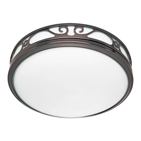
- Page 1 Sona Bath Ventilator with Light Owner’s Manual Model 83002 41951-01 20131201...
-
Page 2: Preventative Maintenance
TO REDUCE THE RISK OF FIRE, ELECTRIC SHOCK, OR INJURY TO PERSONS, OBSERVE THE FOLLOWING: 1. Use this unit only in a manner intended by the manufacturer. American Society for Heating, Refrigeration and Air-Conditioning If you have questions, contact the manufacturer. Engineers (ASHRAE), and the local code authorities. -
Page 3: Before Installation
Check all the parts. 95044-01-000 If damaged, call 95022-01-000 1-888-880-3267 for replacements. 75190-01-000 03242-07-133 95492-05-000 74508-03-133 3/8” Cable Connector 77520-01 65219 96371-01-444 Extra Screws 75184-01-133 NOTE: Strain relief cable connector must be installed. Not Included. 96370-02-444 Included Tools Needed. (Not supplied.) Estimated assembly time: 30 to 60 minutes Before Installation NOTE: Remove all packing materials before installation. - Page 4 Remove the motor/blower from the housing. Remove packing material. Remove the pre-loaded screw tip covers. Back out the pre-loaded screw tips until flush with the side of the housing. Remove the wiring cover screw. Remove the wiring cover. 41951-01 12/01/2013...
- Page 5 Pop out the first wiring access slug. Use second if needed. Insert the strain relief (not included) into the housing and secure with washer. Choose Installation Option For New Construction - attaching to joist go to step A11, page 5 For New Construction - suspended between joists go to step B11, page 8 For Existing Construction - accessible from above go to step C11, page 11 For Existing Construction - accessible only from below go to step D11, page15...
- Page 6 Route wires through the strain relief. For supply connection, use wires suitable for at least 90º C (194º F). Ground Black Green 2 Pin Bare Copper White Black Main Switch 1 (AC In) Fan Motor White White Night Light Night Light 3 Pin Black Light...
- Page 7 0 0 0 0 0 0 0 0 Connect wiring harness. DO NOT ALLOW THE MOTOR TO Reinstall the motor by inserting the tabs and pushing up HANG FROM THE WIRING HARNESS. into position. Make sure the wires are not pinched between the motor and the housing.
- Page 8 New Construction – suspended between joists Slide the mounting rails into brackets. Position the correct depth mark at the bottom edge of the joist based on the thickness of your sheetrock. 1/8” bit Mark position of screws by using holes as a template. Drill a hole in the center of each outline.
- Page 9 Tighten screws. Route wires through the strain relief. For supply connection, use wires suitable for at least 90º C (194º F). Ground Black Green 2 Pin Bare Copper White Black Main Switch 1 (AC In) Fan Motor White White Night Light Night Light 3 Pin Black...
- Page 10 Connect wiring harness. DO NOT ALLOW THE MOTOR TO Reinstall the motor by inserting the tabs and pushing up into HANG FROM THE WIRING HARNESS. position. Make sure the wires are not pinched between the motor and the housing. Secure the motor by tightening the 2 screws. Turn on the power source.
- Page 11 Existing Construction – accessible from above EXISTING FAN NO EXISTING FAN Remove an existing fan and check to make sure the Use the motor housing as a template to mark position. opening is large enough to accommodate the new motor housing (9”x 9.75”). Cut out an opening for the housing.
- Page 12 Drill a hole in the center of each outline. Insert screws, leaving space between the screw head and the joist. Screws are not provided. Attach the rails onto the screws. Tighten screws. Connect 4” duct and vent to the outside. Tape joints. Route wires through the strain relief.
- Page 13 Tighten the strain relief screws. Ground Black Green 2 Pin Bare Copper White Black Main Switch 1 (AC In) Fan Motor White White Night Light Night Light 3 Pin Black Light Light Switch 1 (AC In) *Option Black Switch 2 (AC In) *Option Fan &...
- Page 14 Reinstall the motor by inserting the tabs and pushing up into Secure the motor by tightening the 2 screws. position. Make sure the wires are not pinched between the motor and the housing. O F F Turn on the power source. Test the motor.
- Page 15 Existing Construction – accessible only from below EXISTING FAN Remove an existing fan and check to make sure the Move the housing into position above the ceiling. opening is large enough to accommodate the new motor housing (9”x 9.75”). Route wires through strain relieif. For supply connection, use Attach existing ducting to duct connector.
- Page 16 Ground Black Green 2 Pin Bare Copper White Black Main Switch 1 (AC In) Fan Motor White White Night Light Night Light 3 Pin Black Light Light Switch 1 (AC In) *Option Black Switch 2 (AC In) *Option Fan & Main Light Together Connect wires as shown.
- Page 17 O F F Turn on the power source. Test the motor. If the motor does not run, check the plug connection. Go to step on page 17 to attach grille. Attaching the Grille Remove the thumbscrews. Connect wiring harness. DO NOT ALLOW THE FIXTURE TO HANG FROM THE WIRING HARNESS.
- Page 18 Position the strain relief bracket between the plugs as Align posts A, B, C and D (stamped into motor housing) shown, and screw into place. with posts A, B, C and D (stamped into light fixture). Slide light fixture over posts. Attach thumbscrews.
-
Page 19: Troubleshooting
Trouble Shooting Problem: Fan does not come on. Solution: the air movement. Problem: Light does not come on. Solution: Problem: Fan is noisy. Solution: If you need parts or service assistance, please call 1-888-880-3267 or visit us at our WEB site at http://www.hunterfan.com. 41951-01 12/01/2013... - Page 20 ING, BUT NOT LIMITED TO, ANY IMPLIED WARRANTY OF MERCHANTABILITY OR FITNESS FOR A PARTICULAR PURPOSE, IN This warranty is voided if your Hunter bath exhaust fan is not purchased and installed in the U.S.A. This warranty excludes and does not cover defects, malfunctions or failures of any Hunter bath exhaust fan which were caused by repairs by persons not authorized by exhaust fan while in your possession, or unreasonable use, including failure to provide reasonable and necessary maintenance.
-
Page 21: Manual Del Propietario
Sona Ventilador para baño con luz Manual del Propietario Modelo 83002 41951-02 20131201... -
Page 22: Mantenimiento Preventivo
A D V E R T E N C I A PARA REDUCIR EL RIESGO DE INCENDIO, CHOQUE ELÉCTRICO O LESIONES A PERSONAS, OBSERVE LO SIGUIENTE: 1. Utilice esta unidad sólo de la manera indicada por el fabrican- Ingenieros Americanos en Calefacción y Aire acondicionado te. -
Page 23: Antes De La Instalación
95044-01-000 componentes. Si están dañados, 95022-01-000 llame al 1-888-880-3267 para obtener un reemplazo. 75190-01-000 03242-07-133 95492-05-000 74508-03-133 Conector de cable de 3/8” 77520-01 65219 96371-01-444 Tornillos adicionales 75184-01-133 NOTA: Debe estar instalado el manguito de alivio de tensión del cable. No incluido. 96370-02-444 Incluido. - Page 24 Retire el material de embalaje. Retire el motor/soplador del alojamiento. Retire las cubiertas de las puntas de tornillo precargadas. nivel con el lado del alojamiento. Retire el tornillo de la cubierta del cableado. Retire la cubierta del cableado. 41951-02 12/01/2013...
- Page 25 Retire el primer tapón metálico de acceso del cableado. Inserte el manguito de alivio de tensión (no se incluye) en la Utilice el segundo si es necesario. Escoja la opción de instalación Para construcción nueva - suspendido entre vigas, vaya al paso B11, página 28 Para construcción existente - accesible desde arriba, vaya al paso C11, página 31 Para construcción existente - accesible sólo desde abajo, vaya al paso D11, página 35 Construcción nueva –...
- Page 26 tension. Para conexiones de alimentación, use alambres adecuados al menos para 90º C (194º F). Tierra Negro Verde pasadores clavijas Cobre desnudo Blanco Negro Interruptor principal 1 (CA) Motor del ventilador Blanco Blanco Luz de noche Rojo Luz de noche pasadores clavijas Negro...
- Page 27 0 0 0 0 0 0 0 0 Conecte el mazo de cables. NO PERMITA QUE EL MOTOR Vuelva a instalar el motor introduciendo las pestañas y CUELGUE DEL MAZO DE CABLES. Asegure el motor apretando los 2 tornillos. Encienda la fuente de alimentación. Vaya al paso E N C E N D I D O...
- Page 28 Construcción nueva – suspendido entre vigas Deslice los rieles de montaje en los soportes. inferior de la viga, según el espesor de su plancha de yeso. broca de 1/8 de pulg. Taladre un agujero en el centro de cada perfil. como una plantilla.
- Page 29 Apriete los tornillos. tension. Para conexiones de alimentación, use alambres adecuados al menos para 90º C (194º F). Tierra Negro Verde pasadores clavijas Cobre desnudo Blanco Negro Interruptor principal 1 (CA) Motor del ventilador Blanco Blanco Luz de noche Rojo Luz de noche pasadores clavijas Negro...
- Page 30 Conecte el mazo de cables. NO PERMITA QUE EL MOTOR Vuelva a instalar el motor introduciendo las pestañas y CUELGUE DEL MAZO DE CABLES. Asegure el motor apretando los 2 tornillos. Encienda la fuente de alimentación. Vaya al paso E N C E N D I D O en la página 37 para A P A G A...
- Page 31 Construcción existente – accesible desde arriba VENTILADOR EXISTENTE SIN VENTILADOR EXISTENTE Utilice el alojamiento del motor como una plantilla para mar- sea suficientemente grande para acomodar el alojamiento car la posición. del motor nuevo (9”x 9.75”). Recorte una abertura para el alojamiento. Deslice los rieles de montaje en los soportes.
- Page 32 Taladre un agujero en el centro de cada perfil. Introduzca los tornillos, dejando espacio entre la cabeza del tornillo y la viga. No se proporcionan los tornillos. Fije los rieles con los tornillos. Apriete los tornillos. tension. Para conexiones de alimentación, use alambres cinta a las uniones.
- Page 33 Apriete los tornillos del aliviador de tensiones. Tierra Negro Verde pasadores clavijas Cobre desnudo Blanco Negro Interruptor principal 1 (CA) Motor del ventilador Blanco Blanco Luz de noche Rojo Luz de noche pasadores clavijas Negro Rojo Interruptor 1 (CA) *Opción Negro Interruptor 2 (CA) *Opción Ventilador y luz principal juntos Conecte los alambres como se muestra.
- Page 34 Vuelva a instalar el motor introduciendo las pestañas y Asegure el motor apretando los 2 tornillos. E N C E N D I D O A P A G A Encienda la fuente de alimentación. conexión del enchufe. Vaya al paso en la página 37 para fijar la rejilla.
- Page 35 Construcción existente – accesible sólo desde abajo VENTILADOR EXISTENTE Mueva el alojamiento a su posición encima del techo. sea suficientemente grande para acomodar el alojamiento del motor nuevo (9”x 9.75”). Conecte el ducto existente con el conector de ducto. tension. Para conexiones de alimentación, use alambres adecuados al menos para 90º...
- Page 36 Tierra Negro Verde pasadores clavijas Cobre desnudo Blanco Negro Interruptor principal 1 (CA) Motor del ventilador Blanco Blanco Luz de noche Rojo Luz de noche pasadores clavijas Negro Rojo Interruptor 1 (CA) *Opción Negro Interruptor 2 (CA) *Opción Ventilador y luz principal juntos Conecte los alambres como se muestra.
- Page 37 E N C E N D I D O A P A G A Encienda la fuente de alimentación. conexión del enchufe. Vaya al paso en la página 37 para fijar la rejilla. Fijación de la rejilla Retire los tornillos de mano. Conecte el mazo de cables.
- Page 38 Alinee los postes A, B, C y D (estampados en la caja del motor) con los postes A, B, C y D (estampados en el artefac- to de iluminación). Deslice la lámpara sobre los postes. Instale los tornillos de mano. ADVERTENCIA: Para reducir el Instale 2 bombillas A-15 de 60 vatios como máximo (No incluidas).
-
Page 39: Solución De Problemas
Solución de problemas Problema: El ventilador no está operando. Solución: cerca de los conductos de ventilación para sentir el movimiento del aire. Problema: La luz no funciona. Solución: Problema: El ventilador hace ruido. Solución: Si necesita repuestos o servicio, llame al 1-888-880-3267 o visite nuestro sitio web en http://www.hunterfan.com. 41951-02 12/01/2013... - Page 40 Extractor de aire para baño, con excepción de reparaciones del motor, como se estipula a continuación. Si el motor de su Extractor de aire para baño Hunter falla en cualquier momento dentro de cinco años después de la fecha de compra debido a una falla de material o mano de obra, la mano de obra y los materiales para reparar la falla serán proporcionados sin costo en nuestro centro...