LG XA64 Service Manual
Hide thumbs
Also See for XA64:
- Owner's manual (14 pages) ,
- Manual (12 pages) ,
- Owner's manual (12 pages)
Chapters
Table of Contents
Troubleshooting

Related Manuals for LG XA64


Summary of Contents for LG XA64
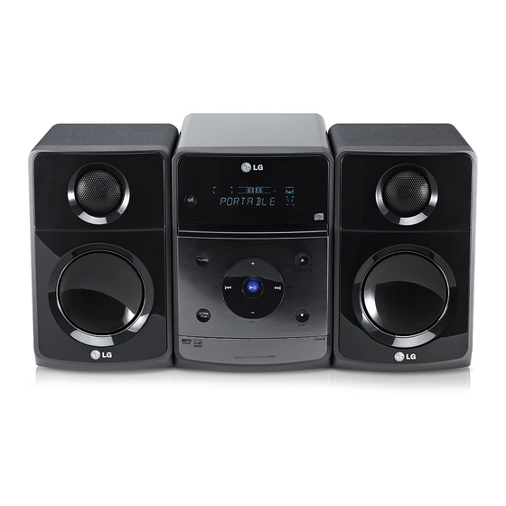
- Page 1 Internal Use Only Website http://biz.lgservice.com MICRO Hi-Fi SYSTEM SERVICE MANUAL MODEL: XA64 (XAS64F) CAUTION BEFORE SERVICING THE UNIT, READ THE “SAFETY PRECAUTIONS” IN THIS MANUAL. NOVEMBER...
- Page 2 CONTENTS SECTION 1 ..SUMMARY SECTION 2 ..CABINET & MAIN CHASSIS SECTION 3 ..ELECTRICAL SECTION 4 ..REPLACEMENT PARTS LIST...
-
Page 3: Table Of Contents
SECTION 1 SUMMARY CONTENTS ........1-3 PRODUCT SAFETY SERVICING GUIDELINES FOR A/V PRODUCTS ........................1-4 SERVICING PRECAUTIONS • GENERAL SERVICING PRECAUTIONS • INSULATION CHECKING PRODEDURE • ELECTROSTATICALLY SENSITIVE (ES) DEVICES ..................1-5 SERVICE INFORMATION FOR EEPROM ........................1-6 PROGRAM UPDATE GUIDE ............................ -
Page 4: Product Safety Servicing Guidelines For A/V Products
When servicing this product, under no circumstances should the original design be modified or altered without permission from LG Corporation. All components should be replaced only with types identical to those in the original circuit and their physical location, wiring and lead dress must conform to original layout upon completion of repairs. -
Page 5: Servicing Precautions
SERVICING PRECAUTIONS CAUTION: Before servicing the A/V products covered by this Electrostatically Sensitive (ES) Devices service data and its supplements and addends, read and fol- Some semiconductor (solid state) devices can be damaged low the SAFETY PRECAUTIONS. easily by static electricity. Such components commonly are NOTE: if unforeseen circumstances create conflict between called Electrostatically Sensitive (ES) Devices. -
Page 6: Service Information For Eeprom
SERVICE INFORMATION FOR EEPROM POWER ON FLD no disc status Front ‘STOP’ + Remote control ‘FWD DETECT NEW EEPROM SKIP’ push same timing during 5s. (OPTION EDIT SCREEN) NAME FLD ‘OP0-xx…. Move to appropriate position and make changes with remote control ‘REPEAT / PLAY / BWD SKIP / FWD SKIP’. -
Page 7: Program Update Guide
1. HOW TO UPDATE ESS PROGRAM (1) Rename the file name to download as “LG_(MODEL NAME)_(Vresion).ROM” in upper cases. ex) XA64 : “LG_XA64_0905180.ROM” Refer to the Standard for naming of software. (2) Copy the file to the formatted USB, and burn it. -
Page 8: Specifications
SPECIFICATIONS • GENERAL Power supply 200 ~ 240 V, 50/60 Hz Power consumption 50 W Net Weight 2.71 kg External dimensions (W x H x D) 170 x 240 x 253 (mm) Operating temperature 5°C ~ 35°C Operating humidity 5 % ~ 85 % •... - Page 9 SECTION 2 CABINET & MAIN CHASSIS CONTENTS ............................. 2-3 EXPLODED VIEWS 1. CABINET AND MAIN FRAME SECTION ....................2-3 2. SPEAKER SECTION ..........................2-7 3. PACKING ACCESSORY SECTION ......................2-8...
-
Page 10: Exploded Views
EXPLODED VIEWS 1. CABINET AND MAIN FRAME SECTION CABLE3 MAIN 259R 259L CABLE1 CABLE2 DISPLAY 255L SMPS 255R... -
Page 11: Speaker Section
2. SPEAKER SECTION A60L A60R... -
Page 12: Packing Accessory Section
3. PACKING ACCESSORY SECTION Battery Remote controller Instruction Ass'y Packing... - Page 13 SECTION 3 ELECTRICAL CONTENTS ELECTRICAL TROUBLESHOOTING GUIDE ..................3-2 1. SMPS PART ............................3-2 2. MUTE ..............................3-3 3. AUDIO ABNORMAL ..........................3-4 4. AUDIO FUNCTION MODE ........................3-5 5. IC301 TROUBLESHOOTING ......................... 3-6 6. IC600 TROUBLESHOOTING ......................... 3-7 7. IC601 TROUBLESHOOTING ......................... 3-8 8.
-
Page 14: Electrical Troubleshooting Guide
ELECTRICAL TROUBLESHOOTING GUIDE 1. SMPS PART 5.0V Is F901 nomal? Replace F901 (Use same type fuse) Replace BD901 Is BD901 nomal? Is RT901 nomal? Replace RT901 VSTR(130V-310V) supplied to Replace R904 IC901 pin5? Vcc(9V-25V) supplied to Is D906, R907 nomal? IC901 pin2? Check or replace D906, R907 Is D914 nomal? -
Page 15: Mute
ELECTRICAL TROUBLESHOOTING GUIDE 2. MUTE Mute Does "High" appear Check U600 pin17 at Q704, Q705 "B"? Check R622 Replace R622 Check IC603 pin69 Check "Low" Replace Q704, Q705 of Q704, Q705 "C" Mute... -
Page 16: Audio Abnormal
ELECTRICAL TROUBLESHOOTING GUIDE 3. AUDIO ABNORMAL Audio abnormal Check the output Check the speakers connection U702 pin2, 4, 8,10 Check the input signal Check the "High" of U702 pin5 of U702 pin7, 11 Check the DC 9.5V Check the function input of U503 pin24 Check the DC 12V Check ZD703, D705... -
Page 17: Audio Function Mode
ELECTRICAL TROUBLESHOOTING GUIDE 4. AUDIO FUNCTION MODE Portable Check the input signal Check the input signal of CON541 of U503 pin7, 8 Check the output signal of U503 pin19, 23 CD / USB Check the input signal Check the output signal of U502 pin55, 57 of U503 pin3, 4 and refer to CD trobleshooting Check the output signal of U503 pin19, 23... -
Page 18: Ic301 Troubleshooting
ELECTRICAL TROUBLESHOOTING GUIDE 5. IC301 TROUBLESHOOTING VFD display check Check the power supply Refer to power troubleshooting to IC301 pin9, 50, 51 Check Check CON301 pin7 STB, pin8 Data, pin9 CS IC301 pin1 CS, pin3 STB pin2, 4 Data Check IC603 pin91 STB, pin57 Data, pin56 CS Check IC301 pin7 FOSC Check or replace R302... -
Page 19: Ic600 Troubleshooting
ELECTRICAL TROUBLESHOOTING GUIDE 6. IC600 TROUBLESHOOTING IC600 troubleshooting Check Refer to power supply no 3.3V both end voltage or check and replace Q600 Q600 (3.3V) Check IC603 pin5 is "H", Check Q601 is "H" check and replace Q601 Check Check or replace L600 IC604 pin13 is 3.3V Check IC600 pin1, 6 and X601... -
Page 20: Ic601 Troubleshooting
ELECTRICAL TROUBLESHOOTING GUIDE 7. IC601 TROUBLESHOOTING IC601 troubleshooting Check Check Refer to MCU IC603 voltage IC601 pin34: CLK, MCU troubleshooting 1.2V pin35: CKE Check MCU IC603 Replace MCU 8. IC603 TROUBLESHOOTING IC603 troubleshooting Check Refer both end voltage both end voltage of IC605 of IC501, IC605 3.3V/1.2V (1.2V/3.3V) Check IC603... -
Page 21: U503 Troubleshooting
ELECTRICAL TROUBLESHOOTING GUIDE 9. U503 TROUBLESHOOTING U503 troubleshooting Check the power supply to Refer to power troubleshooting U503 pin24 Check Check JK501 pin47, 48 Vol_CLK/Vol_Data the SCL/SDA data of U503 pin25, 26 Check the control function Check or replace U503 10. -
Page 22: Cd Part
ELECTRICAL TROUBLESHOOTING GUIDE 11. CD PART Turn on CD Check open/close Refer to CD reading troubleshooting Check connector CN702 Check "READING" display open 0V, close 1.5V Check reading OK Check connector CN503 Check pick-up movement Check U504 BA5826 Check U502 If play, check audio output Check U502 pin55, 57 3-10... -
Page 23: Cd Reading Check
ELECTRICAL TROUBLESHOOTING GUIDE 12. CD READING CHECK Check connector locking CN1, CN500, CN503 Does sled motor move? Check CN500 pin3, 4 (SL+, SL-) Defective pick-up or U502, U504 Check CN503 pin13,16 (F+, F-) Does the laser move? Defective pick-up or U502, U504 Check CN503 pin10 (LD) Does laser light? Defective pick-up or Q501... -
Page 24: Usb Part
ELECTRICAL TROUBLESHOOTING GUIDE 13. USB PART Turn on USB Check "CHECKING" Check CN401 or "USB" display Check power supply circuit USB +5V Check reading OK Check CN401 pin2 5V Check uCOM IC603 Check CN401 pin3, 4 (D+, D-) pin116, 117 (D+, D-) If play, check audio output Check U502 pin55, 57 Check uCOM IC603... -
Page 25: Waveforms
WAVEFORMS 1. CD SEARCHING WAVEFORM U502 PIN61 EE U502 PIN62 TE U502 PIN60 FE 2. SPINDLE DRIVE & MOTOR WAVEFORM U504 PIN27 SL- U504 PIN26 SL+ U504 PIN1 SP- U504 PIN2 SP+ 3-13... -
Page 26: Cd Playing Waveform
3. CD PLAYING WAVEFORM U502 PIN62 TE U502 PIN61 EE U502 PIN60 FE U504 PIN2 SP+ U502 PIN14 TD U502 PIN13 FD 3-14... -
Page 27: Cd Stop Action Waveform
4. CD STOP ACTION WAVEFORM U504 PIN2 SP+ U504 PIN26 SLE+ U504 PIN11 T+ U504 PIN18 F+ 5. CD READING WAVEFORM U502 PIN41 MCK U502 PIN19 DIN U502 PIN20 R/W U502 PIN21 BUSY 3-15... -
Page 28: Cd Playing Rf Waveform
U502 PIN39 LRCK U502 PIN40 BCK U502 PIN41 MCK U502 PIN38 DATA 6. CD PLAYING RF WAVEFORM U502 PIN63 RF 3-16... -
Page 29: Usb Operating Waveform
7. USB OPERATING WAVEFORM CON4 PIN2 D- CON4 PIN1 +5V CON4 PIN3 D+ 8. RADIO OPERATING WAVEFORM U701 PIN2 DA U701 PIN8 RST U701 PIN1 SCK 3-17... -
Page 30: Wiring Diagram
WIRING DIAGRAM MAIN PCB MD ASSY 16P FFC 7.01.1.U9543017R(AM) 6P WIRE MCU PCB 7.01.1.U9543016R(RDS) 2P WIRE B T B CNT 7.05.1.CDM33001R 7.01.Z.XA140001R 3P WIRE SMPS PCB 10P WIRE 6P WIRE 7P WIRE 7.01.9.XA640004R 3P WIRE 6P WIRE Front PCB FRONT PCB KEY PCB 4P WIRE Earphone PCB... -
Page 31: Block Diagrams
BLOCK DIAGRAM FL +/- TDA7292 PORTABLE FR +/- 6 OHM 30W BD3490 VOL/MUX/ Power TUNER L/R TU-SDA, TU-SCL, RESET RDS_CLK, -24V DUAL WM8782 INVERT STEREO 74LCV2G04 SMPS D+/D- 11.2896MHZ A, B, C, D, E, F, PD, LD PICK UP BU9543KV PICK UP IIS CLK TR +/-, F +/-... -
Page 32: Circuit Diagrams
BE MODIFIED OR ALTERED WITHOUT PERMISSION FROM THE ACTUAL CIRCUIT USED. THIS WAY, 2. Voltages are DC-measured with a digital voltmeter 1. SMPS CIRCUIT DIAGRAM FROM THE LG CORPORATION. ALL COMPONENTS IMPLEMENTATION OF THE LATEST SAFETY AND during Play mode. SHOULD... -
Page 33: Main Circuit Diagram
2. MAIN CIRCUIT DIAGRAM 32 30 3-25 3-26... -
Page 34: Main - Cd Circuit Diagram
3. MAIN - CD CIRCUIT DIAGRAM 18 24 19 20 21 3-27 3-28... -
Page 35: Mcu Circuit Diagram
4. MCU CIRCUIT DIAGRAM 3-29 3-30... -
Page 36: Front, Usb & Headphone Circuit Diagram
5. FRONT, USB & HEADPHONE CIRCUIT DIAGRAM 3-31 3-32... -
Page 37: Circuit Voltage Chart
CIRCUIT VOLTAGE CHART PIN NO. TEST VOLT(V) PIN NO. TEST VOLT(V) PIN NO. TEST VOLT(V) PIN NO. TEST VOLT(V) PIN NO. TEST VOLT(V) PIN NO. TEST VOLT(V) PIN NO. TEST VOLT(V) PIN NO. TEST VOLT(V) IC301(PT6324) 1.65 1.65 2.15 2.12 DGND 1.65 1.65... -
Page 38: Printed Circuit Board Diagrams
PRINTED CIRCUIT BOARD DIAGRAMS 1. MAIN P.C.BOARD (TOP VIEW) (BOTTOM VIEW) 3-35 3-36... -
Page 39: Smps P.c.board
2. SMPS P.C.BOARD 3. MCU P.C.BOARD (TOP VIEW) (BOTTOM VIEW) 3-37 3-38... -
Page 40: Key P.c.board
4. KEY P.C.BOARD 5. FRONT P.C.BOARD 3-39 3-40...
Need help?
Do you have a question about the XA64 and is the answer not in the manual?
Questions and answers