
Related Manuals for Iqinvision 4K Sentinel series


Summary of Contents for Iqinvision 4K Sentinel series
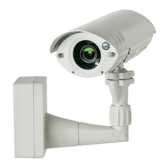
- Page 1 IQeye 4K Sentinel™ Series Indoor/Outdoor Camera Installation and Operating Instructions...
-
Page 2: Table Of Contents
Contents Unpacking Service Description Installation Parts List Camera Fittings Mounting Options Camera Arm Removal Mounting the Power Data Back Box Terminating Power and Data Cabling Inside the Back Box Camera Arm Installation Installing / Adjusting the Sunshield PC Configuration of IQeye Sentinel Camera / Lens Adjustment / Remote Back Focus... -
Page 3: Unpacking
1 Unpacking Unpack carefully. This is an electromechanical device and should be handled carefully. Check to ensure the following items are included: > Integrated Sentinel camera/housing unit > Sunshield > 3 mm Allen wrench > Wall mount template > CD-ROM >... -
Page 4: Installation
4 Installation NOTE: This manual describes how to install the IQeye Sentinel Series camera system, and details the wall, ceiling and parapet mounting options. Installations should be performed by qualified service personnel only in accordance with local codes. 5 Parts List The following depicts the parts included (Figure 1): 1. -
Page 5: Mounting Options
7 Mounting Options Ceiling Mount Wall Mount Parapet Mount Figure 2 8 Camera Arm Removal NOTE: The camera/arm needs to be removed from the back box to allow the back box to be mounted to the designated mounting wall, ceiling, or parapet surface. 1. -
Page 6: Mounting The Power Data Back Box
9 Mounting the Power / Data Back Box Before mounting the power / data back box, determine if the camera installation will be wall, ceiling, or parapet and if the wiring will pass through the compression fittings in the back or the ½” NPT conduit mount on the bottom of the back box. -
Page 7: Terminating Power And Data Cabling Inside The Back Box
10 Terminating Power and Data Cabling Inside the Back Box Power and data cabling must be routed to the right side (wall-side) of the back box. Cut all cables with sufficient slack to reach the connector terminals in the back box but not long enough to be pinched or obstruct the arm installation. Camera-Side Terminations Wall-Side Terminations - RJ-45... -
Page 8: Camera Arm Installation
11 Camera Arm Installation The back box is provided with arm hangers on both sides to hold the camera/ arm module on the back box to facilitate installation. (Figure 8) NOTE: The arm hangers function perfectly at any orientation of the junction box and will firmly hold the camera and junction box cover in any of the wall, ceiling, or parapet mount configurations. - Page 9 5. If mounting the unit outdoors, please take necessary and thorough measures to ensure the camera unit is properly sealed from inclement weather. An example would be to use silicone sealer around the back of the base, being sure to surround all holes with a generous bead of sealant to the outer edge of the back box surface.
-
Page 10: Installing / Adjusting The Sunshield
12 Installing / Adjusting the Sunshield CAUTION The IQeye Sentinel sunshield is not captive to the camera enclosure. Handle the sunshield securely during adjustment, installation and / or removal. NOTE: A sunshield is supplied with the Sentinel for protection against the sun, rain and other environmental factors. -
Page 11: Pc Configuration Of Iqeye Sentinel
b. Removal – With the set screw loose, pull the sunshield forward until it is free of the sunshield bracket. c. Optional – The bracket that holds the sunshield can also be removed if desired. To remove the sunshield bracket, loosen and remove the two (2) 3 mm countersunk screws using the supplied 3 mm Allen wrench. - Page 12 3. To view a camera, double click a camera entry or highlight a camera in the list and click the “Web Page” button (Figure 14). The “Live” page will be displayed through the default browser (IE recommended). It is also possible to open Internet Explorer and enter the IP address of the IQeye camera in the address field of the browser.
-
Page 13: Camera / Lens Adjustment / Remote Back Focus
14 Camera / Lens Adjustment / Remote Back Focus 1. Using the supplied 3mm Allen wrench, loosen any two adjacent screws of the four available ball pivot screws (Figure 16). This should loosen the ball enough to allow repositioning of the camera to the desired orientation. Tighten the screws to secure the camera module in place. - Page 14 4. Browse to the camera homepage and go to the Setup > Focus tab (Figure 19). Figure 19 5. Set the iris on the lens to the ‘Open’ position then lock it down with the iris set screw. 6. If the back focus has been set before using the camera, click the “restore defaults”...
- Page 15 The following image (Figure 21) is an example of an image focused enough to ensure a remote one-touch focus can be completed. Figure 21 NOTE: A desiccant pack is provided for placement inside the lens cover assembly. The desiccant pack must be installed to prevent fogging of the inside of the lens glass due to any moisture that is present when installing the camera.
-
Page 16: Shipping Instructions
Shipping Instructions Use the following procedure when returning a unit to the factory: 1. Call or write Vicon for a Return Authorization (R.A.) at one of the locations listed below. Record the name of the Vicon employee who issued the R.A. Vicon Industries Inc. -
Page 17: Vicon Standard Equipment Warranty
Vicon Standard Equipment Warranty Vicon Industries Inc. (the “Company”) warrants your equipment to be free from defects in material and workmanship under Normal Use from the date of original retail purchase for a period of three years, with the following exceptions: 1. - Page 18 operating manual for the product or normal maintenance, (b) to cosmetic damages, (c) if the product is modified or tampered with, (d) if the product is damaged by acts of God, misuse, abuse, negligence, accident, normal wear and tear and deterioration, improper environmental conditions (including, but not limited to, electrical surges, water damage, chemical exposure, an/or heat/cold exposure) or lack of responsible care, (e) if the product has had the model or serial number altered, defaced or removed, (f) to consumables (such...
- Page 20 901-0370 Rev C 135 Fell Court Hauppauge, NY 11788 www.vicon-security.com...