Sign In
Upload
Manuals
Brands
Toshiba Manuals
All in One Printer
e-STUDIO280S
Toshiba e-STUDIO280S Manuals
Manuals and User Guides for Toshiba e-STUDIO280S. We have
2
Toshiba e-STUDIO280S manuals available for free PDF download: Service Manual
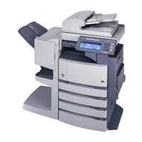
Toshiba e-STUDIO280S Service Manual (354 pages)
MULTIFUNCTIONAL DIGITAL SYSTEMS
Brand:
Toshiba
| Category:
All in One Printer
| Size: 17.5 MB
Table of Contents
Service Manual
1
Table of Contents
7
1 Specifications / Accessories / Options / Supplies
11
Specifications
11
Accessories
16
Options
17
E-STUDIO200L/230/230L/280/280S
17
E-STUDIO202L/203L/232/232S/233/282/282S/283/283S
18
Supplies
20
E-STUDIO200L/230/230L/280/280S
20
E-STUDIO202L/232/232S/282/282S
20
E-STUDIO203L/233/283/283S
20
System List
21
E-STUDIO200L/230/230L/280/280S
21
E-STUDIO202L/203L/232/232S/233/282/282S/283/283S
27
2 Outline of the Machine
35
Sectional View
35
Electric Parts Layout
38
Front Side
39
Symbols and Functions of Various Components
51
General Description
60
System Block Diagram
60
Construction of Boards
62
Installation and Replacement of Covers and PC Boards
64
Covers
64
PC Boards
75
Installation and Replacement of Options
85
3 Copy Process
105
General Description of Copying Process
105
Details of Copying Process
106
Comparison with E-STUDIO350/450
117
4 General Operation
119
Overview of Operation
119
Description of Operation
120
Warming-Up
120
Ready State (Ready for Copying)
120
Drawer Feed Copying (Upper Drawer Paper Feeding)
121
Bypass Feed Copying
123
Interruption Copying
123
Detection of Abnormality
124
Types of Abnormality
124
Description of Abnormality
125
Flow Chart
130
Immediately after the Power Is Turned on
130
Automatic Paper Feed Copying
132
5 Control Panel
135
Control Panel and Display Panel
135
Items Shown on the Control Panel
136
Display
137
Relation between the Equipment State and Operator's Operation
142
Description of Operation
146
Dot Matrix LCD Circuit
146
LED Display Circuit
149
Disassembly and Replacement
150
6 Scanner
155
Function
155
Construction
156
Description of Operation
158
Scan Motor
158
Scanning Drive Circuit
159
Initialization at Power-ON
161
Control of Exposure Lamp
162
General Description
162
Exposure Lamp
163
Control Circuit for the Exposure Lamp
164
General Description of CCD Control
165
Opto-Electronic Conversion
165
Shading Correction
165
Automatic Original Size Detection Circuit
166
Principle of Original Size Detection
166
Process of Detection of Original Size
167
Disassembly and Replacement
171
7 Image Processing
185
General Description
185
Configuration
187
SLG Board
188
Features
188
Functions of Image Processing Circuit
188
LGC Board
192
Features
192
Functions of Image Processing Circuit
192
Laser Driving PC Board
193
8 Laser Optical Unit
195
General Description
195
Structure
197
Laser Diode
200
Polygonal Motor
201
Internal Cooling Fan-2
202
Disassembly and Replacement
203
9 Paper Feeding System
207
Functions
207
Operation
211
Operation of Bypass Pickup Roller
211
Operation of Drawer Pickup Roller
212
Separation of Paper
213
Operation of Clutch
214
General Operation
215
Drive Circuit of Tray-Up Motor
217
Disassembly and Replacement
219
10 Drive System
243
General Description
243
Functions
244
Main Motor
245
Main Motor Drive
245
Control Signals
246
Disassembly and Replacement
247
11 Drum Related Section
251
Configuration
251
Functions
252
High-Voltage Transformer Output Control Circuit
254
General Description
254
Description of Operation
255
Drum Temperature Detection Circuit
256
General Description
256
Construction
256
Temperature/Humidity Detection Circuit
257
General Description
257
Construction
257
Disassembly and Replacement
258
12 Development System
271
Configuration
271
Functions
272
General Description
272
Recovered Toner Supply Mechanism
273
Drive Circuit of Toner Motor
274
Auto-Toner Circuit
276
General Description
276
Function of Auto-Toner Sensor
277
Disassembly and Replacement
279
13 Fuser Unit
291
General Description
291
Operation
292
Functions
293
Heater Control Circuit
295
Configuration
295
Temperature Detection Section
296
Disassembly and Replacement
301
14 Paper Exit Section
309
General Description
309
Functions
310
Control Circuit of Exit Motor
311
Exit Motor Drive
312
Disassembly and Replacement
313
15 Automatic Duplexing Unit (Adu) (Option: MD-0102)
317
General Description
317
Description of Operations
318
Drive of ADU
323
Flow Chart
324
Disassembly and Replacement
326
16 Power Supply Unit
335
Construction
335
Operation of DC Output Circuits
336
Output Channel
337
Fuse
339
Configuration of Power Supply Unit
340
Sequence of Power Supply
341
AC Wire Harness
342
17 Pc Boards
343
2004 - 2008 TOSHIBA TEC CORPORATION All Rights Reserved E-STUDIO200L/202L/203L/230/232/233/280/282/283
343
Advertisement
Toshiba e-STUDIO280S Service Manual (322 pages)
Brand:
Toshiba
| Category:
All in One Printer
| Size: 15.68 MB
Table of Contents
Table of Contents
7
1 Specifications / Accessories / Options / Supplies
11
E-STUDIO200L/230/280
11
Specifications
11
Accessories
16
Options
17
Supplies
18
System List
19
2 Outline of the Machine
25
Sectional View
25
Electric Parts Layout
28
Symbols and Functions of Various Components
39
General Description
48
System Block Diagram
48
Construction of Boards
49
Installation and Replacement of Covers and PC Boards
51
Covers
51
PC Boards
58
Installation and Replacement of Options
64
3 Copy Process
83
General Description of Copying Process
83
Details of Copying Process
84
Comparison with E-STUDIO350/450
95
4 General Operation
97
Overview of Operation
97
Description of Operation
98
Warming-Up
98
Ready State (Ready for Copying)
98
Drawer Feed Copying (Upper Drawer Paper Feeding)
99
Bypass Feed Copying
101
Interruption Copying
101
Detection of Abnormality
102
Types of Abnormality
102
Description of Abnormality
103
Flow Chart
108
Immediately after the Power Is Turned on
108
Automatic Paper Feed Copying
110
5 Control Panel
113
Control Panel and Display Panel
113
Items Shown on the Control Panel
114
Display
115
Relation between the Equipment State and Operator's Operation
120
Description of Operation
124
Dot Matrix LCD Circuit
124
LED Display Circuit
127
Disassembly and Replacement
128
6 Scanner
131
Function
131
Construction
132
Description of Operation
134
Scan Motor
134
Scanning Drive Circuit
135
Initialization at Power-ON
137
Control of Exposure Lamp
138
General Description
138
Exposure Lamp
139
Control Circuit for the Exposure Lamp
140
General Description of CCD Control
141
Opto-Electronic Conversion
141
Shading Correction
141
Automatic Original Size Detection Circuit
142
Principle of Original Size Detection
142
Process of Detection of Original Size
143
Disassembly and Replacement
147
7 Image Processing
159
General Description
159
Configuration
161
SLG Board (PWA-F-SLG-371)
162
Features
162
Functions of Image Processing Circuit
162
LGC Board (PWA-F-LGC-371)
166
Features
166
Functions of Image Processing Circuit
166
Laser Driving PC Board
167
8 Laser Optical Unit
169
General Description
169
Structure
171
Laser Diode
174
Polygonal Motor
175
Internal Cooling Fan-2
176
Disassembly and Replacement
177
9 Paper Feeding System
181
Functions
181
Operation
185
Operation of Bypass Pickup Roller
185
Operation of Drawer Pickup Roller
186
Separation of Paper
187
Operation of Clutch
188
General Operation
189
Drive Circuit of Tray-Up Motor
191
Disassembly and Replacement
193
10 Drive System
215
General Description
215
Functions
216
Main Motor
217
Main Motor Drive
217
Control Signals
218
Disassembly and Replacement
219
11 Drum Related Section
223
Configuration
223
Functions
224
High-Voltage Transformer Output Control Circuit
226
General Description
226
Description of Operation
227
Drum Temperature Detection Circuit
228
General Description
228
Construction
228
Temperature/Humidity Detection Circuit
229
General Description
229
Construction
229
Disassembly and Replacement
230
12 Development System
243
Configuration
243
Functions
244
General Description
244
Recovered Toner Supply Mechanism
245
Drive Circuit of Toner Motor
246
Auto-Toner Circuit
248
General Description
248
Function of Auto-Toner Sensor
249
Disassembly and Replacement
251
13 Fuser Unit
263
General Description
263
Operation
264
Functions
265
Heater Control Circuit
267
Configuration
267
Temperature Detection Section
268
Disassembly and Replacement
273
14 Paper Exit Section
281
General Description
281
Functions
282
Control Circuit of Exit Motor
283
Exit Motor Drive
284
Disassembly and Replacement
285
15 Automatic Duplexing Unit (Adu) (Option: MD-0102)
289
General Description
289
Description of Operations
290
Drive of ADU
295
Flow Chart
296
Disassembly and Replacement
298
16 Power Supply Unit
307
Construction
307
Operation of DC Output Circuits
308
Output Channel
309
Fuse
311
Configuration of Power Supply Unit
312
Sequence of Power Supply
313
AC Wire Harness
314
17 Pc Boards
315
Advertisement
Related Products
Toshiba e-STUDIO280
Toshiba e-STUDIO280L
Toshiba e-STUDIO2803AM
Toshiba e-STUDIO287CSL
Toshiba e-STUDIO283
Toshiba e-STUDIO282S
Toshiba e-STUDIO283S
Toshiba e-STUDIO283C
Toshiba e-STUDIO283L
Toshiba e-STUDIO282L
Toshiba Categories
Laptop
Air Conditioner
TV
LCD TV
All in One Printer
More Toshiba Manuals
Login
Sign In
OR
Sign in with Facebook
Sign in with Google
Upload manual
Upload from disk
Upload from URL