Sign In
Upload
Manuals
Brands
Panasonic Manuals
Home Theater System
SB-HC70
Panasonic SB-HC70 Manuals
Manuals and User Guides for Panasonic SB-HC70. We have
2
Panasonic SB-HC70 manuals available for free PDF download: Service Manual
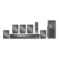
Panasonic SB-HC70 Service Manual (132 pages)
DVD Home Theater Sound System
Brand:
Panasonic
| Category:
Home Theater System
| Size: 9.11 MB
Table of Contents
Table of Contents
1
1 Safety Precautions
3
General Guidelines
3
Before Repair and Adjustment
3
Protection Circuitry
4
Safety Parts Information
4
2 Warning
5
Prevention of Electrostatic Discharge (ESD) to Electrostatic Sensitive (ES) Devices
5
Precaution of Laser Diode
6
Service Caution Based on Legal Restrictions
7
Handling Precautions for Traverse Unit
8
3 Service Navigation
10
Service Information
10
4 Specifications
11
5 Location of Controls and Components
13
Remote Control Key Button Operations
13
Main Unit Key Button Operations
14
Speaker Connection
14
Using the VIERA Link "HDAVI Control
15
Disc Information
17
6 Self-Diagnosis and Special Mode Setting
19
Cold-Start
19
Service Mode Table
19
Self-Diagnosis Mode
25
DVD Self Diagnostic Function-Error Code
26
Sales Demonstration Lock Function
29
Firmware Version-Up Information
30
7 Troubleshooting Guide
33
Troubleshooting Guide for F61 And/Or F76
33
Basic Troubleshooting Guide for Traverse Unit (DVD Module P.C.B.)
37
Basic Troubleshooting Guide for HDMI AV Output
38
8 Disassembly and Assembly Instructions
40
Disassembly Flow Chart
41
Main Components and P.C.B. Locations
42
Disassembly of Top Cabinet
43
Disassembly of Component Video P.C.B
43
Disassembly of Voltage Selector P.C.B
44
Disassembly of Rear Panel
45
Disassembly of DVD Mechanism Unit (DLS6E)
45
Disassembly of DVD Module P.C.B
47
Disassembly of SMPS P.C.B
48
Replacement of Switching Regulator IC (IC5701)
49
Replacement of Diode (D5802)
50
Disassembly of Main/D-Amp P.C.B
51
Replacement of Digital Amplifier IC (IC403/ IC404/IC405)
52
Disassembly of Front Panel Assembly
54
Disassembly of FL P.C.B
55
Disassembly of Volume Button P.C.B
56
Disassembly of Power Button P.C.B
57
Replacement of DVD Lid Assembly
58
9 Assembling and Disassembling of Traverse Unit
61
Disassembly of Traverse Unit
61
Assembly of Traverse Unit
62
10 Service Position
63
Checking & Repairing Main/D-Amp P.C.B. & Component Video P.C.B
63
Checking & Repairing of SMPS P.C.B
63
Checking & Repairing of FL P.C.B
64
Checking & Repairing of DVD Module P.C.B
65
11 Voltage & Waveform Chart
67
DVD Module P.C.B. (1/4)
67
DVD Module P.C.B. (2/4)
68
DVD Module P.C.B. (3/4)
69
DVD Module P.C.B. (4/4)
70
Main P.C.B. (1/3)
71
Main P.C.B. (2/3)
72
Main P.C.B. (3/3)
73
Fl P.C.b
74
Smps P.C.b
74
Component Video P.C.B
75
Waveform Table (1/3)
76
Waveform Table (2/3)
77
Waveform Table (3/3)
78
12 Illustration of Ics, Transistor and Diode
79
13 Overall Simplified Block Diagram
81
14 Block Diagram
82
DVD(Servo)
82
DVD(Audio/Video)
83
DVD(Up-Con)
84
System Control
85
Analog Audio
86
Digital Audio
87
Analog Video
88
Power Supply
89
15 Wiring Connection Diagram
91
16 Schematic Diagram Notes
93
17 Schematic Diagram
95
DVD Module Circuit
95
Main/D-Amp Circuit
100
FL, Volume Button & Power Button Circuit
106
Component Video Circuit
107
SMPS Circuit
108
Voltage Selector Circuit
110
18 Printed Circuit Board
111
DVD Module P.C.B
111
Main/D-Amp P.C.B
112
FL, Volume Button, Power Button & Component Video P.C.B
114
SMPS & Voltage Selector P.C.B
115
19 Terminal Function of Ics
117
Ic200 (Rfkwmpt75Phk): IC Microprocessor
117
IC901(C0HBB0000057): IC FL Driver
117
20 Exploded View and Replacement Parts List
119
Exploded View and Mechanical Replacement Part List
119
Electrical Replacement Part List
122
Advertisement
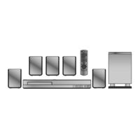
panasonic SB-HC70 Service Manual (131 pages)
DVD Home Theater Sound System
Brand:
panasonic
| Category:
Home Theater System
| Size: 8.92 MB
Table of Contents
Table of Contents
1
1 Safety Precautions
3
General Guidelines
3
Before Repair and Adjustment
4
Protection Circuitry
5
Safety Parts Information
5
2 Warning
6
Prevention of Electrostatic Discharge (ESD) to Electrostatic Sensitive (ES) Devices
6
Precaution of Laser Diode
7
Service Caution Based on Legal Restrictions
8
Handling Precautions for Traverse Unit
9
3 Service Navigation
11
Service Information
11
4 Specifications
12
Others (Licences)
13
5 Location of Controls and Components
14
Remote Control and Main Unit Key Button Operations
14
Main Unit Key Button Operations
15
Power-Saving Features
15
Speaker Connection
16
Linked Operations with the TV (VIERA LINK "HDAVI Control™")
17
Connection with an ARC Compatible TV
19
Disc Information
20
6 Operating Instructions
22
Removing of Disc During Abnomality
22
7 Self-Diagnostic and Special Mode Setting
24
Cold-Start
24
Service Mode Table
24
Self-Diagnostic Mode
30
Self Diagnostic Function-Error Code
31
Sales Demonstration Lock Function
33
Firmware Version-Up Information
34
8 Troubleshooting Guide
36
Troubleshooting Guide for F61 And/Or F76
36
DVD/CD Laser Diode Current
39
Measurement.this Section will Illustrate Proceddures of Measuring& Deriving DVD/CD Laser Diode Current
39
Basic Troubleshooting Guide for Traverse Unit (Backend P.C.B.)
41
Basic Troubleshooting Guide for HDMI AV Output
42
9 Service Fixture & Tools
43
Service Tools and Equipment
43
10 Disassembly and Assembly Instructions
44
Disassembly Flow Chart
45
Main Components and P.C.B. Locations
46
Disassembly of Top Cabinet
47
Disassembly of Rear Panel
48
Disassembly of Front Panel Assembly
48
Disassembly of Panel P.C.B
49
Disassembly of Power Button P.C.B
51
Disassembly of DVD Mechanism Unit (BRS1D)
52
Replacement of Traverse Unit
54
Disassembly of Main P.C.B
59
Replacement of Digital Amplifier IC (IC403/ IC404/IC405)
61
Disassembly of SMPS P.C.B
63
Replacement of Current Limiting Switch (Q5701)
65
Replacement of Diode (D5706)
66
Disassembly of Backend P.C.B
67
11 Service Position
69
Checking & Repairing Main P.C.B. (Side B)
69
Checking & Repairing Main P.C.B. (Side A)
69
Checking & Repairing of SMPS P.C.B
70
Checking & Repairing of Panel P.C.B
70
Checking & Repairing of DVD Module P.C.B
70
12 Voltage & Waveform Chart
72
Backend P.C.B. (1/3)
72
Backend P.C.B. (2/3)
73
Backend P.C.B. (3/3)
74
Main P.C.B. (1/3)
75
Main P.C.B. (2/3)
76
Main P.C.B. (3/3)
77
Panel P.C.B
78
Smps P.C.b
78
Waveform Table (1/2)
79
Waveform Table (2/2)
80
Illustration of Ics, Transistor and Diode
81
Overall Simplified Block Diagram
83
Block Diagram
84
Backend
84
IC Terminal Chart
85
System Control
86
Audio & Video
87
Power Supply
89
Wiring Connection Diagram
91
Schematic Diagram
93
Schematic Diagram Notes
93
Backend Circuit
95
Main Circuit
101
Panel & Power Button Circuit
109
SMPS Circuit
110
Printed Circuit Board
112
Backend P.C.B
112
Main P.C.B
113
Panel & Power Button P.C.B
115
Smps P.C.b
116
Terminal Function of Ics
117
Ic200 (Rfkwmxh50Eb): IC Microprocessor
117
IC6001 (C0HBB0000057): IC FL Display Driver
118
Exploded View and Replacement Parts List
119
Exploded View and Mechanical Replacement Parts List
119
Electrical Replacement Parts List
123
Advertisement
Related Products
Panasonic SB-HC730
Panasonic SB-HC760
Panasonic SB-HC75
Panasonic SB-HC750P
Panasonic SB-HC460
Panasonic SB-HC470
Panasonic SB-HC5000
Panasonic SB-HC4000
Panasonic SB-HC300
Panasonic SB-HC4010
Panasonic Categories
Camcorder
Air Conditioner
TV
Digital Camera
Cordless Telephone
More Panasonic Manuals
Login
Sign In
OR
Sign in with Facebook
Sign in with Google
Upload manual
Upload from disk
Upload from URL