Sign In
Upload
Manuals
Brands
Panasonic Manuals
Cassette Player
AJ-SD93P/E
Panasonic AJ-SD93P/E Manuals
Manuals and User Guides for Panasonic AJ-SD93P/E. We have
1
Panasonic AJ-SD93P/E manual available for free PDF download: Service Manual
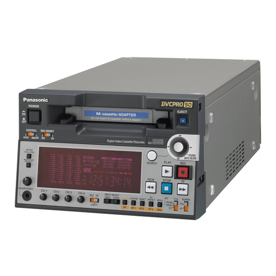
Panasonic AJ-SD93P/E Service Manual (180 pages)
Digital Video Cassette Recorder
Brand:
Panasonic
| Category:
Cassette Player
| Size: 8.58 MB
Table of Contents
Service Information
13
Table of Contents
13
Servicing Fixtures & Tools
14
Alignment Tape
17
VFM3380KM (NTSC) (50M Adjustment Tape)
17
VFM3010EDS / EDL (NTSC) (DV Adjustment Tape)
17
VFM3580KM / KL (NTSC) (25M Adjustment Tape)
17
VFM3582KM / KL (NTSC) (Manufacturer (X-Value) Adjustment Tape)
17
VFM3581KM / KL (NTSC) (Manufacturer (LISTA) Adjustment Tape)
17
VFM3000EDS / EDL (NTSC/PAL) (DV (LISTA) Adjustment Tape)
18
VFM3680KM / KL (PAL) (25 M Adjustment Tape)
18
VFM3681KM / KL (PAL) (Manufacturer (LISTA) Adjustment Tape)
18
VFM3682KM / KL (PAL) (Manufacturer (X-Value) Adjustment Tape)
18
VFM3480KM (PAL) (50M Adjustment Tape)
18
VFM3110EDS / EDL (PAL) (DV Adjustment Tape)
19
List of Recommended Measuring Instruments
19
Maintenance
20
Maintenance Schedule
20
Layout of the Maintenance Parts
21
Layout of the Other Parts
21
MANUAL TAPE EJECT (Emergency Eject)
22
Pinch Roller and Capstan Shaft Cleaning Method: (Weekly)
23
Post Cleaning Method: (Weekly)
23
Cylinder Head Cleaning Method: (Daily)
23
A/C Head Cleaning Method: (Weekly)
23
Cylinder Lead Cleaning Method: (Weekly)
23
Cleaning Method
23
Software Version Display
24
SOFTWARE and PLD VERSION Are Displayed on the VIDEO SUPER out (Monitor TV) and FRONT DISPLAY
24
Error Rate Display
26
Diag Menu Display
28
Tp & Main Signal for Tape Path Confirmation
30
Internal Switch Setting
32
Microcomputer (FLASH) / PLD Chart
33
Software Version Upgrade Method
33
Flash ROM / FPG Software Version Upgrade Procedure
34
Service Menu
45
Service Menu Operation Method
45
DEFAULT Operation
46
Service Menu Contents
47
Error Messages
65
Writing UID
69
Node Unique ID (Uid)
69
Confirmation of UID Number
69
Circuit Board Layout Drawing
71
Disassembly Procedures
72
Bottom Case Removal
73
Disassembly Procedures
73
Front Loading Unit Removal
73
Front Panel Removal
73
Top Panel Removal
73
Rear Panel Removal
74
MECHA if 3 Board Removal
75
Power Supply Unit Disassembly
75
Power Supply Unit Removal
75
Mechanism Chassis Unit Removal
76
Mechanical Adjustment
77
Name of Tape Transportation
79
Table of Test Point
80
Table of Test Point, VR, Setting for Service Menu
80
Mechanical Adjustment Procedures
81
Post Height Pre-Adjustment
81
Tension Arm Adjustment Flowchart
81
Tension Sensor Voltage Adjustment (1)
82
Tension Sensor Voltage Adjustment (2)
82
Tension Arm PLAY and REV Voltage Confirmation
83
Tension Regulator Spring Adjustment
83
REV Tension Confirmation
84
Tension Confirmation
85
Photo Sensor Voltage Adjustment
86
Tape Path Adjustment Procedure
87
Envelope Waveform Adjustment
88
Post Limit Confirmation (PLAY)
88
A/C Head Adjustment Method (General)
89
A/C Head Height Adjustment
91
A/C Head Tilt Adjustment
91
A/C Head Height Confirmation
92
A/C Head Tilt Confirmation
92
A/C Head Azimuth and X-Value Adjustment
93
Compensation Adjustment of X Value
94
REV Tape Path Confirmation and Adjustment (T4 Post Height Adjustment)
94
CTL Self Recording Level Confirmation
95
Play Tape Path Limit Confirmation
95
Confirmation of Envelope on REV, REW and FF Mode
96
Confirmation of Play Start Envelope
96
FF, REW Mode Tape Path Limit Confirmation
97
REV Mode Tape Path Limit Confirmation
97
Screw Lock Tight of A/C Head and T3, T4 Posts
97
Confirmation of Tape Damage for Long Tape Playback
98
LISTA Adjustment Procedure
99
LISTA Connection and Boot up
100
How to Enter the Attachment Data of Alignment Tape
102
RP Head Sensitivity Adjustment and Sensitivity Detection (25M Mode)
103
LISTA Linearity Adjustment and Waving Measurement (25M Mode)
105
PB Head LISTA Sensitivity Adjustment and Sensitivity Detection (25M Mode)
107
RP Head Sensitivity Adjustment and Sensitivity Detection (50M Mode)
109
LISTA Linearity Adjustment and Waving Measurement (50M Mode)
111
PB Head LISTA Sensitivity Adjustment and Sensitivity Detection (50M Mode)
113
RP HEAD (for DV) Lista Sensitivity Adjustment
115
Self-REC/PLAY Envelope Waveform Confirmation
117
Tape Loading Method
117
Cylinder Unit Replacement
118
Major Mechanical Parts Replacement & Adjustment Procedures
118
Cleaning Arm Unit Replacement
119
T1 Guide Position Adjustment
119
Adjustment Flow Chart after Cylinder Unit Replacement
120
Supply & Take-Up Reel Rotor Unit Replacement
121
Main Brake Torque Confirmation
122
Supply & Take-Up Brake Arm Unit Replacement
122
Supply Brake Solenoid Replacement and Adjustment
122
Take-Up Brake Solenoid Replacement and Adjustment
123
Pinch Solenoid Position Adjustment
124
Pinch Solenoid Replacement
124
Loading Motor Replacement
125
Pinch Arm Unit Replacement
125
Main Cam Gear Replacement
126
Mode SW Unit Replacement
126
S5 Post Base Unit Replacement
127
Thrust Screw Replacement and Adjustment
127
Tension Arm Unit Replacement
128
S1 Post Loading Arm Unit Replacement & Adjustment
129
T1 Boat Unit Replacement and Adjustment
130
A/C Head Replacement & Adjustment
132
Cleaner Solenoid Replacement & Adjustment
133
Distinction SW Unit Replacement
135
Reel Drive Motor Unit Replacement
135
L-M Release Angle Unit Replacement
136
Slide Rod Unit Replacement & Adjustment
136
M-Stopper Solenoid Replacement & Adjustment
137
Connector Location
138
Mech. I/F P.C. Board
138
T4 Post Position Adjustment
138
Electrical Adjustment
139
Power Supply Voltage Adjustment
140
Power Unit
140
Servo Board (F1)
140
Motor Torque Offset Adjustment
141
Reel Torque Gain Adjustment
141
Tension Sensor Voltage Adjustment (1)
142
Tension Sensor Voltage Adjustment (2)
142
PG Shifter Adjustment (25M)
143
PG Shifter Adjustment (50M)
143
Avmon Board (F2)
144
PLL DC Adjustment
144
Avio Board [Aj-Ya93] (F4)
145
4-1A. Reference CF Detection Adjustment (NTSC)
146
4-2A. Component y Level Adjustment (NTSC)
146
4-1B. Reference CF Detection Adjustment (PAL)
147
4-2B. Component y Level Adjustment (PAL)
147
Audio Initial Setting
148
Audio Input Level Adjustment
148
Audio Output Level Adjustment
148
Rf/Cue Board
149
RF Level Adjustment (25M)
150
RF Level Adjustment (50M)
150
RF Level Adjustment (DV)
151
Block Diagrams
159
Interconnection Block Diagram
160
Video /Audio Overall Block Diagram
161
Servo (F1) Block Diagram
162
Mecha if Block Diagram
163
Avmon (F2) Block Diagram
164
Dproc (F3) Block Diagram
165
Ieee1394 Module (F3 Sub) Block Diagram
166
Avio (F4) Block Diagram
167
Sdi (F5) Block Diagram
168
Rf/Cue Block Diagram
169
Advertisement
Advertisement
Related Products
Panasonic AJ-D93MC
Panasonic AJ-YAC930G
Panasonic AJSD930B - DVCPRO 50 DECK
Panasonic AJ-SD93
Panasonic AJ-SD93E
Panasonic AJ-SD93P
Panasonic AJ-SD930BE
Panasonic AJSD930BP - DVC PRO50 DECK
Panasonic AJ-SD930
Panasonic AJ-SD930E
Panasonic Categories
Camcorder
Air Conditioner
TV
Digital Camera
Cordless Telephone
More Panasonic Manuals
Login
Sign In
OR
Sign in with Facebook
Sign in with Google
Upload manual
Upload from disk
Upload from URL